EP1944178A1 - Dispositif de climatisation pour un véhicule automobile - Google Patents
Dispositif de climatisation pour un véhicule automobile Download PDFInfo
- Publication number
- EP1944178A1 EP1944178A1 EP07033591A EP07033591A EP1944178A1 EP 1944178 A1 EP1944178 A1 EP 1944178A1 EP 07033591 A EP07033591 A EP 07033591A EP 07033591 A EP07033591 A EP 07033591A EP 1944178 A1 EP1944178 A1 EP 1944178A1
- Authority
- EP
- European Patent Office
- Prior art keywords
- air
- air conditioning
- fuel cell
- motor vehicle
- vehicle
- Prior art date
- Legal status (The legal status is an assumption and is not a legal conclusion. Google has not performed a legal analysis and makes no representation as to the accuracy of the status listed.)
- Withdrawn
Links
Images


Classifications
-
- B—PERFORMING OPERATIONS; TRANSPORTING
- B60—VEHICLES IN GENERAL
- B60H—ARRANGEMENTS OF HEATING, COOLING, VENTILATING OR OTHER AIR-TREATING DEVICES SPECIALLY ADAPTED FOR PASSENGER OR GOODS SPACES OF VEHICLES
- B60H1/00—Heating, cooling or ventilating devices
- B60H1/00642—Control systems or circuits; Control members or indication devices for heating, cooling or ventilating devices
- B60H1/00735—Control systems or circuits characterised by their input, i.e. by the detection, measurement or calculation of particular conditions, e.g. signal treatment, dynamic models
- B60H1/00757—Control systems or circuits characterised by their input, i.e. by the detection, measurement or calculation of particular conditions, e.g. signal treatment, dynamic models by the input of sound, e.g. by using a voice synthesizer
-
- Y—GENERAL TAGGING OF NEW TECHNOLOGICAL DEVELOPMENTS; GENERAL TAGGING OF CROSS-SECTIONAL TECHNOLOGIES SPANNING OVER SEVERAL SECTIONS OF THE IPC; TECHNICAL SUBJECTS COVERED BY FORMER USPC CROSS-REFERENCE ART COLLECTIONS [XRACs] AND DIGESTS
- Y02—TECHNOLOGIES OR APPLICATIONS FOR MITIGATION OR ADAPTATION AGAINST CLIMATE CHANGE
- Y02T—CLIMATE CHANGE MITIGATION TECHNOLOGIES RELATED TO TRANSPORTATION
- Y02T90/00—Enabling technologies or technologies with a potential or indirect contribution to GHG emissions mitigation
- Y02T90/40—Application of hydrogen technology to transportation, e.g. using fuel cells
Definitions
- the invention relates to a method for controlling a fuel cell system, which is associated with an air conditioner for stationary air conditioning of a motor vehicle for operating a refrigeration circuit, wherein the air conditioner outputs system messages to the user.
- the invention relates to an air conditioner for stationary air conditioning of a motor vehicle, with a fuel cell system for operating a refrigeration circuit and with a signal generator for notifying system messages.
- the invention relates to a motor vehicle with such an air conditioner.
- the air conditioning system builds on the generic state of the art in that the air conditioner outputs the system messages acoustically.
- An acoustic system message ensures that the user is informed of the system message without delay and reliably.
- the acoustic system message is output as soon as a user get into the vehicle. This informs the user of the system message even before the journey starts. The user can thus take action on the stationary air conditioning system before departure, if prompted by the system message.
- the acoustic system message is output as soon as the ignition of the motor vehicle is turned on.
- the air conditioning system according to the invention and the motor vehicle according to the invention with such an air conditioning system provide the aforementioned advantages in a metaphorical manner.
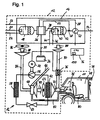
- FIG. 1 shows a schematic representation of an air conditioner according to the invention.
- the installed in a motor vehicle 10 air conditioning 12 (installation position see Fig. 2 ), in the FIG. 1 is outlined with a dashed line, comprises as main elements a fuel cell system 14 and a refrigerant circuit 16.
- the fuel cell system 14 includes a reformer 18, which is supplied via a fuel train 20 from a fuel tank, not shown, fuel. Further, the reformer 18 at a second Brennstoffzu 150069 by means of a fuel train 22 also from the fuel tank fuel can be supplied. As fuel types are diesel, gasoline, natural gas and other known from the prior art types of fuel in question. Furthermore, the reformer 18 via an oxidant strand 24 oxidizing agent, ie in particular air, fed. The reformate produced by the reformer 18 can be fed to a fuel cell stack 26. Alternatively, instead of the fuel cell stack 26, only one fuel cell may be provided.
- the reformate is a hydrogen-containing gas which is reacted in the fuel cell stack 26 with the aid of cathode feeds via a cathode feed line 28 to generate electrical energy and heat.
- the generated electrical energy can be fed via an electrical line 30 to an electric motor 32, a battery 34 and an electric heater 36 of the air conditioning system 12.
- the anode exhaust gas can be fed via an anode exhaust line 38 to a mixing unit 40 of an afterburner 42.
- the Afterburner 42 via a fuel train 44 fuel from the fuel tank and via an oxidant strand 46 oxidizing agent fed.
- conveyors such as pumps, arranged.
- conveyors in this case, preferably blower arranged. These conveyors can be powered directly from the fuel cell stack 26 or from the battery 34.
- the low-emission combustion exhaust gas flows through a heat exchanger 52 for preheating the cathode feed air and finally leaves the fuel cell system 14 via an exhaust gas outlet 54.
- a compressor 56 In the refrigerant circuit 16, a compressor 56, a condenser 58, an expansion device 60 and an evaporator 62 are arranged.
- the compressor 56 can be driven by the electric motor 32, which in turn is preferably supplied with energy by the fuel cell stack 26 of the fuel cell system 14, but can also be supplied with energy by the battery 34 for a short time.
- the evaporator 62 is associated with a blower 64. Ambient air can be drawn in from the outside via an outside air line 66.
- the term "from outside”, as used in connection with this invention, means from outside the interior 78, thus denotes the surrounding the motor vehicle 10 air.
- the outside air duct 66 leads to an adjusting device 68, which can supply the outside air to the blower 64.
- the air directed from the actuator 68 to the fan 64 flows past the evaporator 62 as airflow 70. In this way, the air flow 70 through the evaporator 62 heat energy can be withdrawn.
- the cooled air stream can then be fed via an adjusting device 72 and an air guide 74 via a hat rack 76 a vehicle interior 78.
- the adjusting device 72 can be realized, for example, by a solenoid valve or by check valves, which in each case allow only one flow from the two supply lines to the air guide 74.
- the cooled air flows through the vehicle interior 78 (as indicated by arrows in FIG Fig. 2 illustrated) and leaves it below a seat 80, preferably the rear seat.
- the air flows via an air guide 82 back to the adjusting device 68, where it is completely or partially discharged to the outside or back to the blower 64 is passed.
- a corresponding line is provided, which is not shown for reasons of clarity.
- the circuit of the adjusting device 68 thus makes it possible to realize either a fresh air or a circulating air concept in which air is drawn in from outside via the outside air line 66 or the air is recirculated from the air duct 82. Mixed forms of these modes are possible.
- the air introduced via the outside air duct 66 can be supplied to an air duct 84 and via this to a blower 86.
- this air flows as air stream 88 hot parts of the fuel cell system 14 pass directly or by (not shown) heat exchanger, which mediate between the air stream 88 and the hot parts.
- the hot parts of the fuel cell system 14 are preferably the reformer 18, the fuel cell stack 26 and the afterburner 42. In this way, heat energy can be supplied to the air stream 88 by the waste heat of the hot parts of the fuel cell system 14.
- the heated air stream 88 leads via an air guide 90 to the electric heater 36, which is supplied directly from a power generated by the fuel cell stack 26 or stored by the battery 34 energy.
- the already preheated air in the air duct 90 can be further heated and fed via the adjusting device 72 and the air guide 74 to the interior 78.
- Cooling operation with circulating air circulation In this operating state, the adjusting device 68 is switched so that air from the interior 78 via the air guide 82 to the fan 64 is performed. This air flow 70 is cooled and guided via the adjusting device 72 and the air guide 74 into the interior 78, whereby it is cooled.
- corresponding blowers and lines are provided, which reduce the waste heat of the air conditioning system 12 (in particular of the fuel cell system 14, the condenser 58, the compressor 56 and of the electric motor 32) to the outside. In the case of the capacitor 58, this could alternatively also be arranged on the outside of the vehicle 10, in order thus to remove the waste heat directly.
- Cooling operation with outside air supply In this operating state, the adjusting device 68 is switched so that outside air is guided via the outside air line 66 to the blower 64. The air flow 70 is cooled and guided via the adjusting device 72 and the air guide 74 into the interior 78. The over the air guide 82 from the interior 78 leading air flow is discharged from the actuator 68 to the outside. With regard to the removal of the waste heat of the air conditioner 12, the measures explained in the context of the cooling operation described above are taken.
- Heating mode with circulating air circulation In this operating state, an air flow 88 is guided from the interior 78 to the fan 86 via the air guide 82, the adjusting device 68 and the air guide 84.
- the refrigeration circuit 16 is not in operation, ie the electric motor 32 is not operated.
- the blower 86 passes the air stream 88 past the hot parts of the fuel cell system 14. The way this way preheated air is guided by means of the air guide 90 to the electric heater 36 and on to the adjusting device 72.
- the electric heater 36 is operated to heat the air in the air duct 90 with electric power. Subsequently, the heated air flows via the adjusting device 72 and the air guide 74 into the interior space 78.
- Heating mode with outside air supply In this operating state, outside air is supplied via the outside air line 66 from the adjusting device 68 of the air guide 84. The waste heat generated by the operation of the fuel cell system 14 heats the air flow 88. This heated air flow is, as in the above-described operating state, conducted via the air guide 90, the electric heater 36, the actuator 72 and the air guide 74 in the interior 78. Subsequently, this air flow is guided via the air guide 82 to the adjusting device 68, where it is discharged to the outside.
- This electronic control unit 96 selects the appropriate operating state depending on the temperature in the interior 78, outside temperature, set target temperatures and desired air conditioning operation.
- This electronic control unit 96 has a system message memory 100 and is at least with the corresponding conveyors in the strands 20, 22, 24, 44 and 46 of the power distribution in the electrical line 30, the fans 64 and 86, the electric heater, the electric motor 32, the adjusting devices 68 and 72, the corresponding temperature sensors and the acoustic signal generator 98 is connected.
- the electronic control unit 96 is connected to at least one sensor by means of which it can be determined whether a user is in the motor vehicle 10. There are several ways to determine if a user is in the vehicle.
- the electronic control unit can be determined by coupling the electronic control unit with the ignition of the motor vehicle 10, whether the ignition is turned on. If the ignition is switched on, it can be deduced that a user is in the motor vehicle 10. Furthermore, it can be determined via a pressure sensor in a vehicle seat, preferably the driver's seat, whether a person is sitting in this vehicle seat. In addition, the electronic control device by means of another sensor, such as a door opening sensor, a motion sensor, etc., determine whether a user is in the motor vehicle 10.
- FIG. 2 shows a schematic representation of the motor vehicle 10 with the inventive air conditioner 12.
- the air conditioner 12 according to the invention can be mounted in the trunk, preferably as a retrofittable unit.
- the motor vehicle 10 has a conventional air conditioning system 92, in which a compressor of a conventional refrigeration circuit is mechanically drivable by a drive unit 94, preferably an internal combustion engine.
- the interior 78 may be cooled via the conventional on-board air conditioning system 92 in a well-known manner or be heated by means of waste heat of the drive unit 94.
- the drive unit 94 is at a standstill, the interior 78 can be conditioned via the air conditioning system 12 according to the invention.
- FIG. 3 shows a flowchart of the air conditioning operation of the air conditioner 12 of the invention.
- the routine FIG. 3 which is executed by the electronic control unit 96, starts at step S100 when the air conditioner 12 is turned on manually.
- step S101 it is determined whether the power plant 94 is still operating. The process does not proceed to step S102 until the query in step S101 is negative.
- step S102 it is determined whether the user has selected an automatic standby air conditioning operation via a selector switch or a corresponding programming of the air conditioner 12. If not, the process proceeds to step S103 where it is determined whether the user has manually selected standby air conditioning. If this is not the case, then the process proceeds to step S104, where it is determined whether the user has manually selected comfort climate control.
- step S105 at which a comfort air-conditioning is performed.
- a comfort air-conditioning In this Wohlfühlertleiter the interior 78 of the motor vehicle 10 is air conditioned to a comfort temperature (eg 18 ° C) by a selection of the different heating and cooling modes is made by the electronic control unit 96.
- the subsequent step S106 determines that this feel-good air conditioning is automatically stopped when the power plant 94 is started.
- step S106 determines whether the power plant 94 is not running yet. If it is determined in step S107 whether the air conditioner 12 has been turned off manually. For a manual shutdown, the process ends at step S112, otherwise the process returns to step S105. If the user has not selected feel-good conditioning in step S104, the process returns from there to step S101. If it has been determined in step S102 that an automatic standby air conditioning has been selected, then the process proceeds from there to step S108, where it is determined whether a comfortable air conditioning has been manually selected by the user. If so, then the process proceeds to step S105, where the well-being conditioning described above is performed.
- step S109 the standby air conditioning according to the present invention is performed.
- the temperature in the interior 78 is controlled to a standby set temperature (eg, 25 ° C), which is different from the comfort temperature. This is realized by suitably selecting the electronic control unit 96 from the described heating and cooling modes. If the outside temperature is high, then the ready set temperature is greater than the comfort temperature. If, however, the outside temperature is low, then the ready set temperature is lower than the comfort temperature.
- step S109 the process proceeds to step S110, where it is checked whether the power plant 94 has been started. If so, then the process returns to step S100. Otherwise, the process proceeds to step S111 where it is determined whether the user has manually turned off the air-conditioning - if "YES”, then the process ends in step S112 and if "NO", then the process returns to step S108.
- the preferred operation of the air conditioning system 12 in practice is to select automatic standby air conditioning. If the drive unit 94 is operated, then the interior space 78 can be conditioned via the vehicle-optimized, very effective and specially designed air conditioning system 92. Once the power plant 94 is turned off (and the occupants may leave the vehicle 10), the air conditioner 12 starts the ready air conditioning, which cools the interior at high outside temperature, for example, 25 ° C. This standby air conditioning operation can be carried out with 12 liters of fuel without any problems for 12 days in continuous operation. The stand-by air conditioning operation is performed until the user selects feel-good air conditioning just before starting to drive, which then cools the interior 78 to, for example, 18 ° C. The Wohlfühlrytmaschine is then carried out until the drive unit 94 is started again or until the pollutant concentration in the ambient air is greater than the predetermined pollutant threshold.
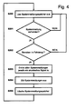
- FIG. 4 shows a flowchart of the acoustic system message output according to the invention.
- the routine off FIG. 4 preferably runs permanently during the operation of the stationary air conditioner 12 from.
- system messages of all kinds, such as a request for refilling of fuel, the current temperature, etc., are permanently stored in the system message memory 100.
- step S200 then in the routine FIG. 4 the system message memory 100 is read, then the routine proceeds to step S201. If system messages to be issued there are stored, the routine proceeds to step S202. In the event that no system messages are stored in the system message memory 100, the routine returns to a queue on step S200.
- step S202 it is determined whether the user is in the vehicle. There are the possibilities already described.
- step S202 If it is determined in step S202 that there is no user in the vehicle, the routine returns in a waiting loop to step S200.
- this holding pattern has the effect that in the case of stationary air conditioning and a person-free vehicle, the system message is only issued when a person gets into the vehicle and this is ascertained by the methods mentioned above.
- step S203 an acoustic signal is assigned to each system message.
- acoustic signals preferably stored voice messages are used, but also an output of beeps is possible.
- these voice messages are then finally output via the acoustic signal generator 98 or an on-board audio system, and then the Signal message memory 100 cleared before the routine finally returns to step S200.
Landscapes
- Physics & Mathematics (AREA)
- Thermal Sciences (AREA)
- Engineering & Computer Science (AREA)
- Mechanical Engineering (AREA)
- Air-Conditioning For Vehicles (AREA)
- Fuel Cell (AREA)
Applications Claiming Priority (1)
| Application Number | Priority Date | Filing Date | Title |
|---|---|---|---|
| DE102007001661A DE102007001661A1 (de) | 2007-01-11 | 2007-01-11 | Klimaanlage für ein Kraftfahrzeug |
Publications (1)
| Publication Number | Publication Date |
|---|---|
| EP1944178A1 true EP1944178A1 (fr) | 2008-07-16 |
Family
ID=39283911
Family Applications (1)
| Application Number | Title | Priority Date | Filing Date |
|---|---|---|---|
| EP07033591A Withdrawn EP1944178A1 (fr) | 2007-01-11 | 2007-12-27 | Dispositif de climatisation pour un véhicule automobile |
Country Status (3)
| Country | Link |
|---|---|
| EP (1) | EP1944178A1 (fr) |
| DE (1) | DE102007001661A1 (fr) |
| WO (1) | WO2008083674A1 (fr) |
Citations (4)
| Publication number | Priority date | Publication date | Assignee | Title |
|---|---|---|---|---|
| EP0034373A1 (fr) * | 1980-02-18 | 1981-08-26 | Nippondenso Co., Ltd. | Appareillage pour commander un dispositif de conditionnement d'air d'un véhicule |
| US4503528A (en) * | 1981-03-05 | 1985-03-05 | Nippondenso Co., Ltd. | Method and apparatus for controlling vehicle mounted devices and equipment |
| WO2003093737A1 (fr) | 2002-04-29 | 2003-11-13 | Bergstrom, Inc. | Systeme de climatisation et de chauffage pour un vehicule operationnel pendant le fonctionnement et l'arret de moteur |
| DE10307976A1 (de) * | 2003-02-24 | 2004-09-02 | Behr Gmbh & Co. Kg | Anzeige für einen Fahrzeuginnenraum |
Family Cites Families (3)
| Publication number | Priority date | Publication date | Assignee | Title |
|---|---|---|---|---|
| DE19715748C1 (de) * | 1997-04-16 | 1998-05-07 | Mc Micro Compact Car Ag | Fahrzeugklimatisierungsüberwachungsvorrichtung |
| US6406806B1 (en) * | 1999-11-09 | 2002-06-18 | General Motors Corporation | Fuel cell voltage monitoring and system control |
| DE102005033404A1 (de) * | 2005-07-18 | 2007-01-25 | Robert Bosch Gmbh | Verfahren zur Vermeidung einer Überhitzung eines Fahrzeuginnenraums sowie Schutzvorrichtung zur Durchführung eines solchen Verfahrens |
-
2007
- 2007-01-11 DE DE102007001661A patent/DE102007001661A1/de not_active Withdrawn
- 2007-12-27 EP EP07033591A patent/EP1944178A1/fr not_active Withdrawn
-
2008
- 2008-01-10 WO PCT/DE2008/000033 patent/WO2008083674A1/fr not_active Ceased
Patent Citations (4)
| Publication number | Priority date | Publication date | Assignee | Title |
|---|---|---|---|---|
| EP0034373A1 (fr) * | 1980-02-18 | 1981-08-26 | Nippondenso Co., Ltd. | Appareillage pour commander un dispositif de conditionnement d'air d'un véhicule |
| US4503528A (en) * | 1981-03-05 | 1985-03-05 | Nippondenso Co., Ltd. | Method and apparatus for controlling vehicle mounted devices and equipment |
| WO2003093737A1 (fr) | 2002-04-29 | 2003-11-13 | Bergstrom, Inc. | Systeme de climatisation et de chauffage pour un vehicule operationnel pendant le fonctionnement et l'arret de moteur |
| DE10307976A1 (de) * | 2003-02-24 | 2004-09-02 | Behr Gmbh & Co. Kg | Anzeige für einen Fahrzeuginnenraum |
Also Published As
| Publication number | Publication date |
|---|---|
| DE102007001661A1 (de) | 2008-07-17 |
| WO2008083674A1 (fr) | 2008-07-17 |
Similar Documents
| Publication | Publication Date | Title |
|---|---|---|
| EP1950064A1 (fr) | Dispositif de climatisation pour véhicule automobile | |
| EP1953015A1 (fr) | Climatisation pour un véhicule automobile | |
| EP1946949B1 (fr) | Dispositif de climatisation pour un véhicule automobile | |
| WO2008037242A1 (fr) | Installation de climatisation pour la climatisation à l'arrêt d'un véhicule automobile | |
| DE102006045755B4 (de) | Klimaanlage für ein Kraftfahrzeug | |
| WO2008037248A1 (fr) | Installation de climatisation pour un véhicule automobile | |
| WO2008037243A1 (fr) | Installation de climatisation pour un véhicule automobile | |
| WO2008095471A1 (fr) | Véhicule automobile équipé d'une installation de climatisation | |
| WO2008037238A1 (fr) | Installation de climatisation pour un véhicule automobile | |
| EP1950065A1 (fr) | Dispositif de climatisation pour un véhicule automobile | |
| WO2008083674A1 (fr) | Système de climatisation pour un véhicule à moteur | |
| DE102007004127A1 (de) | Verfahren zum Steuern einer Klimaanlage | |
| EP1950062A1 (fr) | Dispositif de climatisation pour un véhicule | |
| EP1958805A1 (fr) | Véhicule automobile doté d'une installation destinée à la climatisation | |
| DE102006051741B4 (de) | Verfahren zum Regenerieren eines Reformers | |
| WO2008037244A1 (fr) | Installation de climatisation pour un véhicule automobile | |
| EP1959514A1 (fr) | Climatisation pour un véhicule automobile | |
| WO2008040268A1 (fr) | Système de climatisation pour un véhicule automobile | |
| EP1944822A1 (fr) | Climatisation pour un véhicule automobile | |
| EP1942021A1 (fr) | Installation de climatisation pour un véhicule automobile | |
| DE102006045676A1 (de) | Klimaanlage für ein Kraftfahrzeug | |
| DE102006051740A1 (de) | Verfahren zum Regenerieren eines Reformers | |
| WO2008037247A1 (fr) | Installation de climatisation pour un véhicule automobile | |
| DE102018009269B4 (de) | Klimatisierungseinrichtung für ein Kraftfahrzeug, sowie Kraftfahrzeug damit |
Legal Events
| Date | Code | Title | Description |
|---|---|---|---|
| PUAI | Public reference made under article 153(3) epc to a published international application that has entered the european phase |
Free format text: ORIGINAL CODE: 0009012 |
|
| AK | Designated contracting states |
Kind code of ref document: A1 Designated state(s): AT BE BG CH CY CZ DE DK EE ES FI FR GB GR HU IE IS IT LI LT LU LV MC MT NL PL PT RO SE SI SK TR |
|
| AX | Request for extension of the european patent |
Extension state: AL BA HR MK RS |
|
| AKX | Designation fees paid | ||
| STAA | Information on the status of an ep patent application or granted ep patent |
Free format text: STATUS: THE APPLICATION IS DEEMED TO BE WITHDRAWN |
|
| 18D | Application deemed to be withdrawn |
Effective date: 20090117 |
|
| REG | Reference to a national code |
Ref country code: DE Ref legal event code: 8566 |