EP1944199A2 - Fixation pour capteur d'airbag - Google Patents
Fixation pour capteur d'airbag Download PDFInfo
- Publication number
- EP1944199A2 EP1944199A2 EP08000429A EP08000429A EP1944199A2 EP 1944199 A2 EP1944199 A2 EP 1944199A2 EP 08000429 A EP08000429 A EP 08000429A EP 08000429 A EP08000429 A EP 08000429A EP 1944199 A2 EP1944199 A2 EP 1944199A2
- Authority
- EP
- European Patent Office
- Prior art keywords
- holder
- airbag sensor
- airbag
- body part
- motor vehicle
- Prior art date
- Legal status (The legal status is an assumption and is not a legal conclusion. Google has not performed a legal analysis and makes no representation as to the accuracy of the status listed.)
- Withdrawn
Links
- 238000012360 testing method Methods 0.000 description 7
- 230000004888 barrier function Effects 0.000 description 6
- 230000001133 acceleration Effects 0.000 description 5
- 238000009863 impact test Methods 0.000 description 5
- 238000000034 method Methods 0.000 description 4
- 230000001960 triggered effect Effects 0.000 description 3
- 230000006378 damage Effects 0.000 description 2
- 238000011161 development Methods 0.000 description 2
- 230000018109 developmental process Effects 0.000 description 2
- 238000011156 evaluation Methods 0.000 description 2
- 238000005259 measurement Methods 0.000 description 2
- 238000013459 approach Methods 0.000 description 1
- 238000005253 cladding Methods 0.000 description 1
- 230000003111 delayed effect Effects 0.000 description 1
- 230000001419 dependent effect Effects 0.000 description 1
- 238000013461 design Methods 0.000 description 1
- 230000000694 effects Effects 0.000 description 1
- 230000006870 function Effects 0.000 description 1
- 230000003116 impacting effect Effects 0.000 description 1
- 238000009434 installation Methods 0.000 description 1
- 238000012986 modification Methods 0.000 description 1
- 230000004048 modification Effects 0.000 description 1
- 230000002028 premature Effects 0.000 description 1
- 230000008569 process Effects 0.000 description 1
- 230000002035 prolonged effect Effects 0.000 description 1
- 230000009993 protective function Effects 0.000 description 1
- 238000004088 simulation Methods 0.000 description 1
- 230000004083 survival effect Effects 0.000 description 1
Images


Classifications
-
- B—PERFORMING OPERATIONS; TRANSPORTING
- B60—VEHICLES IN GENERAL
- B60R—VEHICLES, VEHICLE FITTINGS, OR VEHICLE PARTS, NOT OTHERWISE PROVIDED FOR
- B60R21/00—Arrangements or fittings on vehicles for protecting or preventing injuries to occupants or pedestrians in case of accidents or other traffic risks
-
- B—PERFORMING OPERATIONS; TRANSPORTING
- B60—VEHICLES IN GENERAL
- B60R—VEHICLES, VEHICLE FITTINGS, OR VEHICLE PARTS, NOT OTHERWISE PROVIDED FOR
- B60R19/00—Wheel guards; Radiator guards, e.g. grilles; Obstruction removers; Fittings damping bouncing force in collisions
- B60R19/02—Bumpers, i.e. impact receiving or absorbing members for protecting vehicles or fending off blows from other vehicles or objects
- B60R19/48—Bumpers, i.e. impact receiving or absorbing members for protecting vehicles or fending off blows from other vehicles or objects combined with, or convertible into, other devices or objects, e.g. bumpers combined with road brushes, bumpers convertible into beds
- B60R19/483—Bumpers, i.e. impact receiving or absorbing members for protecting vehicles or fending off blows from other vehicles or objects combined with, or convertible into, other devices or objects, e.g. bumpers combined with road brushes, bumpers convertible into beds with obstacle sensors of electric or electronic type
Definitions
- the invention relates to the triggering of airbags of a motor vehicle.
- Modern motor vehicles have one or more airbags that are triggered by associated airbag sensors.
- airbag sensors in the front region of the motor vehicle detect an occurring deformation in the event of a frontal impact.
- impact and crash tests have been developed.
- One example is an impact test according to EuroNCAP (Euro pean N ew C ar A ssessment PROGRAMS) in which collides a motor vehicle at 64 km / hr and a structure covering of 40% frontally against a deformable barrier. This test must ensure that the airbag sensors reliably trigger the airbags.
- a first embodiment of the invention relates to a motor vehicle body with a body part, to which a holder for an airbag sensor is attached.
- the holder faces the vehicle outside, wherein an airbag sensor which can be mounted or mounted on the holder is arranged horizontally spaced from the body part.
- the bracket is more easily deformable in a colliding with her vehicle than the body part holding them.
- a separate holder for the airbag sensor is accordingly provided.
- the bracket faces the vehicle outside so that another vehicle may impact the bracket.
- a possible cladding of the airbag sensor area should be disregarded, since this the typically provides no significant resistance to another vehicle.
- the airbag sensor is attached.
- the deformability of the holder and the body part, to which the holder is attached is measured in the following manner: identical airbag sensors, which are acceleration sensors of their kind, are fastened to the holder and its mounting region on said body part.
- An impact is realized as specified in the EuroNCAP test according to the Euro-NCAP Frontal Impact Testing Protocol, Version 4.1, March 2004.
- the acceleration a (t) measured by the respective airbag sensor has been added up since the impact.
- the airbag sensor attached to the holder Since the airbag sensor attached to the holder is delayed more than the airbag sensor attached to the rigid body part because of the compliance or deformability of its holder, it delivers a stronger signal. This stronger signal is then used in the airbag deployment algorithm for earlier deployment.
- the duration of the signal overshoot can be adjusted via the distance of the installed airbag sensor to said body part.
- the height of the sensor signal can be adjusted via the stiffness of the holder.
- the holder is much easier deformable than the body part holding it. This is understood to mean that with the measuring method described above, the integrated speed of the holder for airbag deployment time by at least 8%, preferably at least 12% and more preferably at least 15% greater than the integrated speed of the associated body part.
- the holder is located on the front of the front top or on the radiator cross member.
- the bracket is thus suitable for a sufficiently early release of the airbag sensors that trigger the front airbags in a frontal collision with complete or partial structural overlap.
- the stated problem of the airbag being released late or too late is particularly pronounced.
- the holder has a first part and a second part, which are arranged one behind the other with respect to a predetermined horizontal direction and in which the first part is less easily deformable than the second part.
- the second part of the holder ensures an acceleration of the airbag sensor and an early airbag sensor signal.
- the first part of the holder fulfills a protective function and prevents premature destruction of the airbag sensor, so that it gives a sensor signal for a sufficiently long time.
- a further embodiment has the Body part, a through opening through which the airbag sensor can be pushed in the event of a collision with another vehicle.
- FIG. 1 a motor vehicle 1 with a body 2. On the outside of the vehicle is mounted on the front top 3, an airbag sensor. 4
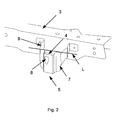
- FIG. 2 shows the installation area of the airbag sensor 4 in a detail. It can be seen that the airbag sensor 4 is attached to a bracket 5, which in turn is attached to the body part 3 (the front top).
- the holder 5 has a hat profile which receives the airbag sensor 4 behind the opening 6.
- the holder 5 has a first part 7, which lies in front of the line L, and a second part 8, which is arranged behind the line L.
- the first part 7 is less easily deformable than the second part 8 and has the task of protecting the airbag sensor 5.
- the second part 8 ensures that the threshold value of the airbag sensor 4, which is used by the airbag airbag deployment algorithm, is reached earlier.
- FIG. 3 shows a further embodiment of a holder 5, which is fastened with its second part 8 at the front top 3.
- the front 3 above and corresponding thereto the second part 8 have a through opening 9 abuts a collision partner along a predetermined Direction P to the unit of holder 5 and airbag sensor 4, the first part 7, the in Fig. 3 is shown transparent, deformed in the direction of the opening 9.
- the airbag sensor 4 is completely or partially pushed in or pushed through the opening 9, and arrives in a secure position. As a result, the life of the airbag sensor 4 is prolonged.
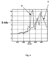
- FIG. 4 shows simulation results for the embodiment of the FIG. 3 ,
- the acceleration a (t) measured by the airbag sensor 4 was read out and with formula 1 the integrated speed was determined. This speed is plotted in m / s as a function of the time in seconds elapsed after the impact. The implementation and evaluation of the measurement was thus carried out according to the measuring method described above.
- the curve A shows the waveform and the integrated speed without a holder according to the embodiment of the FIG. 3 was used.
- the airbag sensor 4 was attached directly outside on the front top 3.
- the curve B shows the waveform, as with the embodiment of the FIG. 3 was obtained.
- the vehicle airbag sensor deployment algorithm is designed to deploy the airbag at a speed of 5 m / s. It can be seen that in curve A, ie according to the state of the art, an airbag deployment has occurred after 40 ms. However, 40 ms is the very latest point in time at which the airbag must be triggered in the case of the concrete structure used for reasons that are of no further interest here. Using the bracket according to Curve B, the airbag sensor 4 reaches the threshold value of 5 m / s after only 32 ms. This time is clearly within the above 40 ms interval. In addition, the signal is stronger. By reaching the threshold of 5 m / s earlier, the airbag sensor algorithm will have more time to deploy the airbag to ensure occupant safety.
Landscapes
- Engineering & Computer Science (AREA)
- Mechanical Engineering (AREA)
- Air Bags (AREA)
Applications Claiming Priority (1)
| Application Number | Priority Date | Filing Date | Title |
|---|---|---|---|
| DE200710001959 DE102007001959A1 (de) | 2007-01-13 | 2007-01-13 | Halterung für einen Airbagsensor |
Publications (2)
| Publication Number | Publication Date |
|---|---|
| EP1944199A2 true EP1944199A2 (fr) | 2008-07-16 |
| EP1944199A3 EP1944199A3 (fr) | 2009-12-30 |
Family
ID=39345535
Family Applications (1)
| Application Number | Title | Priority Date | Filing Date |
|---|---|---|---|
| EP08000429A Withdrawn EP1944199A3 (fr) | 2007-01-13 | 2008-01-11 | Fixation pour capteur d'airbag |
Country Status (2)
| Country | Link |
|---|---|
| EP (1) | EP1944199A3 (fr) |
| DE (1) | DE102007001959A1 (fr) |
Cited By (3)
| Publication number | Priority date | Publication date | Assignee | Title |
|---|---|---|---|---|
| CN108473103A (zh) * | 2015-11-25 | 2018-08-31 | 雷诺股份公司 | 用于安装机动车辆的雷达的装置 |
| US11383660B2 (en) * | 2019-04-05 | 2022-07-12 | The Raymond Corporation | Material handling vehicle having a multi-piece bumper assembly |
| DE102023204618A1 (de) | 2023-05-17 | 2024-11-21 | Volkswagen Aktiengesellschaft | Stützeinheit für ein Fahrzeug, System sowie Fahrzeug |
Family Cites Families (7)
| Publication number | Priority date | Publication date | Assignee | Title |
|---|---|---|---|---|
| DE19718803C1 (de) * | 1997-05-03 | 1998-10-22 | Ford Global Tech Inc | Bestimmen eines Fußgängeraufpralls auf ein Fahrzeug |
| DE19818586C1 (de) * | 1998-04-25 | 1999-09-30 | Daimler Chrysler Ag | Schutzvorrichtung für ein Kraftfahrzeug |
| JP3923801B2 (ja) * | 2002-01-10 | 2007-06-06 | 富士重工業株式会社 | 車両のエアバッグセンサ取付構造 |
| DE10331862C5 (de) * | 2003-07-14 | 2016-04-14 | Volkswagen Ag | Fahrzeugrahmenschutzelement und Verfahren zur Ansteuerung eines Insassenschutzmittels |
| DE102004008005A1 (de) * | 2004-02-19 | 2005-09-08 | Daimlerchrysler Ag | Anordnung zur Sensierung eines Frontaufpralls eines Kraftfahrzeuges |
| DE102004053431A1 (de) * | 2004-11-05 | 2006-05-11 | Bayerische Motoren Werke Ag | Vorrichtung zum Auslösen von passiven Insassen-Sicherheitsmaßnahmen |
| DE102005032082B3 (de) * | 2005-07-08 | 2006-12-21 | Siemens Ag | Trägerprofil für ein Sensorband zum Einbau in den Stoßfänger eines Kraftfahrzeugs und Sensoranordnung |
-
2007
- 2007-01-13 DE DE200710001959 patent/DE102007001959A1/de not_active Withdrawn
-
2008
- 2008-01-11 EP EP08000429A patent/EP1944199A3/fr not_active Withdrawn
Non-Patent Citations (1)
| Title |
|---|
| None |
Cited By (6)
| Publication number | Priority date | Publication date | Assignee | Title |
|---|---|---|---|---|
| CN108473103A (zh) * | 2015-11-25 | 2018-08-31 | 雷诺股份公司 | 用于安装机动车辆的雷达的装置 |
| CN108473103B (zh) * | 2015-11-25 | 2021-11-16 | 雷诺股份公司 | 用于安装机动车辆的雷达的安装装置 |
| US11383660B2 (en) * | 2019-04-05 | 2022-07-12 | The Raymond Corporation | Material handling vehicle having a multi-piece bumper assembly |
| US20220340094A1 (en) * | 2019-04-05 | 2022-10-27 | The Raymond Corporation | Material Handling Vehicle Having a Multi-Piece Bumper Assembly |
| US11577676B2 (en) * | 2019-04-05 | 2023-02-14 | The Raymond Corporation | Material handling vehicle having a multi-piece bumper assembly |
| DE102023204618A1 (de) | 2023-05-17 | 2024-11-21 | Volkswagen Aktiengesellschaft | Stützeinheit für ein Fahrzeug, System sowie Fahrzeug |
Also Published As
| Publication number | Publication date |
|---|---|
| EP1944199A3 (fr) | 2009-12-30 |
| DE102007001959A1 (de) | 2008-07-17 |
Similar Documents
| Publication | Publication Date | Title |
|---|---|---|
| DE112009003176B4 (de) | Kollisionsdetektionssystem | |
| DE10331862C5 (de) | Fahrzeugrahmenschutzelement und Verfahren zur Ansteuerung eines Insassenschutzmittels | |
| EP2073996B1 (fr) | Procede et dispositif destines a declencher un moyen de protection des personnes pour un vehicule | |
| DE102008013546B4 (de) | Kollision-Detektorvorrichtung für ein Automobil | |
| DE102004017270B3 (de) | Vorrichtung zum Erkennen eines Aufpralls auf ein Fahrzeug | |
| DE10016142B4 (de) | Auslöseschalter für ein Personenschutzsystem | |
| EP1237758A1 (fr) | Procede et un dispositif pour activer des installations de protection des occupants d'un vehicule | |
| DE112011105936B4 (de) | Diagnoseanordnung für einen fahrzeugmontierten Fußgängeraufprallsensor | |
| WO2006125719A1 (fr) | Dispositif et procede permettant de commander un systeme de protection de personnes d'un vehicule | |
| DE102014224444B4 (de) | Aufpralldämpfende Bauteilanordnung für ein Kraftfahrzeug | |
| EP1526990B1 (fr) | Dispositif de d tection de collision avec un poteau | |
| EP1501704A1 (fr) | Proc d et disposition pour amorcer des dispositifs de retenue | |
| DE102008017246A1 (de) | Anordnung zur Aufprallerkennung | |
| EP1944199A2 (fr) | Fixation pour capteur d'airbag | |
| DE102017005759A1 (de) | Aktive Türbodenverstärkung | |
| DE102013017957A1 (de) | Verfahren zur Ansteuerung zumindest eines in einem Fahrzeugsitz angeordneten Schutzelementes | |
| DE10212902A1 (de) | Verfahren und Anordnung zur Ansteuerung von insbesondere reversibel ansteuerbaren Rückhaltemitteln | |
| DE102004027862B4 (de) | Sensoreinrichtung für ein Fußgängerschutzsystem und Fußgängerschutzsystem | |
| DE102010031358A1 (de) | Crashstruktur zur Aufnahme von Crashenergie und Verfahren zur Einstellung einer Steifigkeit einer Crashstruktur | |
| DE102005005959A1 (de) | Vorrichtung und Verfahren zum Steuern einer Sicherheitsvorrichtung eines Fahrzeugs | |
| EP3168088B1 (fr) | Véhicule automobile | |
| EP1409298B2 (fr) | Dispositif et procede pour declencher un moyen de protection d'occupant d'un vehicule automobile | |
| DE102014226966B4 (de) | Sicherheitssystem für ein Fahrzeug | |
| DE102007035511B4 (de) | Verfahren zur Auslösung von Schutzmaßnahmen | |
| DE102014013035A1 (de) | Stoßfängeranordnung für einen Personenkraftwagen |
Legal Events
| Date | Code | Title | Description |
|---|---|---|---|
| PUAI | Public reference made under article 153(3) epc to a published international application that has entered the european phase |
Free format text: ORIGINAL CODE: 0009012 |
|
| AK | Designated contracting states |
Kind code of ref document: A2 Designated state(s): AT BE BG CH CY CZ DE DK EE ES FI FR GB GR HR HU IE IS IT LI LT LU LV MC MT NL NO PL PT RO SE SI SK TR |
|
| AX | Request for extension of the european patent |
Extension state: AL BA MK RS |
|
| PUAL | Search report despatched |
Free format text: ORIGINAL CODE: 0009013 |
|
| AK | Designated contracting states |
Kind code of ref document: A3 Designated state(s): AT BE BG CH CY CZ DE DK EE ES FI FR GB GR HR HU IE IS IT LI LT LU LV MC MT NL NO PL PT RO SE SI SK TR |
|
| AX | Request for extension of the european patent |
Extension state: AL BA MK RS |
|
| AKY | No designation fees paid | ||
| STAA | Information on the status of an ep patent application or granted ep patent |
Free format text: STATUS: THE APPLICATION IS DEEMED TO BE WITHDRAWN |
|
| 18D | Application deemed to be withdrawn |
Effective date: 20100701 |
|
| REG | Reference to a national code |
Ref country code: DE Ref legal event code: 8566 |