EP1944475B1 - Wärmeaustauschsystem - Google Patents
Wärmeaustauschsystem Download PDFInfo
- Publication number
- EP1944475B1 EP1944475B1 EP08250063.8A EP08250063A EP1944475B1 EP 1944475 B1 EP1944475 B1 EP 1944475B1 EP 08250063 A EP08250063 A EP 08250063A EP 1944475 B1 EP1944475 B1 EP 1944475B1
- Authority
- EP
- European Patent Office
- Prior art keywords
- flap
- exit
- entrance
- engine
- turbofan engine
- Prior art date
- Legal status (The legal status is an assumption and is not a legal conclusion. Google has not performed a legal analysis and makes no representation as to the accuracy of the status listed.)
- Ceased
Links
- 238000001816 cooling Methods 0.000 claims description 31
- 239000010687 lubricating oil Substances 0.000 claims description 21
- 239000000314 lubricant Substances 0.000 claims description 18
- 238000005461 lubrication Methods 0.000 claims description 11
- 238000000034 method Methods 0.000 claims description 6
- 238000011144 upstream manufacturing Methods 0.000 claims description 4
- 230000001050 lubricating effect Effects 0.000 claims description 2
- 239000000446 fuel Substances 0.000 description 9
- 239000003921 oil Substances 0.000 description 8
- 239000012530 fluid Substances 0.000 description 7
- 238000010438 heat treatment Methods 0.000 description 2
- 230000000694 effects Effects 0.000 description 1
- 238000011084 recovery Methods 0.000 description 1
- 238000010792 warming Methods 0.000 description 1
Images


Classifications
-
- F—MECHANICAL ENGINEERING; LIGHTING; HEATING; WEAPONS; BLASTING
- F01—MACHINES OR ENGINES IN GENERAL; ENGINE PLANTS IN GENERAL; STEAM ENGINES
- F01D—NON-POSITIVE DISPLACEMENT MACHINES OR ENGINES, e.g. STEAM TURBINES
- F01D25/00—Component parts, details, or accessories, not provided for in, or of interest apart from, other groups
- F01D25/08—Cooling; Heating; Heat-insulation
- F01D25/12—Cooling
-
- F—MECHANICAL ENGINEERING; LIGHTING; HEATING; WEAPONS; BLASTING
- F01—MACHINES OR ENGINES IN GENERAL; ENGINE PLANTS IN GENERAL; STEAM ENGINES
- F01D—NON-POSITIVE DISPLACEMENT MACHINES OR ENGINES, e.g. STEAM TURBINES
- F01D25/00—Component parts, details, or accessories, not provided for in, or of interest apart from, other groups
- F01D25/18—Lubricating arrangements
-
- F—MECHANICAL ENGINEERING; LIGHTING; HEATING; WEAPONS; BLASTING
- F02—COMBUSTION ENGINES; HOT-GAS OR COMBUSTION-PRODUCT ENGINE PLANTS
- F02C—GAS-TURBINE PLANTS; AIR INTAKES FOR JET-PROPULSION PLANTS; CONTROLLING FUEL SUPPLY IN AIR-BREATHING JET-PROPULSION PLANTS
- F02C7/00—Features, components parts, details or accessories, not provided for in, or of interest apart form groups F02C1/00 - F02C6/00; Air intakes for jet-propulsion plants
- F02C7/12—Cooling of plants
- F02C7/14—Cooling of plants of fluids in the plant, e.g. lubricant or fuel
-
- F—MECHANICAL ENGINEERING; LIGHTING; HEATING; WEAPONS; BLASTING
- F02—COMBUSTION ENGINES; HOT-GAS OR COMBUSTION-PRODUCT ENGINE PLANTS
- F02C—GAS-TURBINE PLANTS; AIR INTAKES FOR JET-PROPULSION PLANTS; CONTROLLING FUEL SUPPLY IN AIR-BREATHING JET-PROPULSION PLANTS
- F02C9/00—Controlling gas-turbine plants; Controlling fuel supply in air- breathing jet-propulsion plants
- F02C9/16—Control of working fluid flow
- F02C9/18—Control of working fluid flow by bleeding, bypassing or acting on variable working fluid interconnections between turbines or compressors or their stages
-
- F—MECHANICAL ENGINEERING; LIGHTING; HEATING; WEAPONS; BLASTING
- F02—COMBUSTION ENGINES; HOT-GAS OR COMBUSTION-PRODUCT ENGINE PLANTS
- F02K—JET-PROPULSION PLANTS
- F02K3/00—Plants including a gas turbine driving a compressor or a ducted fan
- F02K3/08—Plants including a gas turbine driving a compressor or a ducted fan with supplementary heating of the working fluid; Control thereof
- F02K3/105—Heating the by-pass flow
- F02K3/115—Heating the by-pass flow by means of indirect heat exchange
-
- F—MECHANICAL ENGINEERING; LIGHTING; HEATING; WEAPONS; BLASTING
- F05—INDEXING SCHEMES RELATING TO ENGINES OR PUMPS IN VARIOUS SUBCLASSES OF CLASSES F01-F04
- F05D—INDEXING SCHEME FOR ASPECTS RELATING TO NON-POSITIVE-DISPLACEMENT MACHINES OR ENGINES, GAS-TURBINES OR JET-PROPULSION PLANTS
- F05D2240/00—Components
- F05D2240/10—Stators
- F05D2240/12—Fluid guiding means, e.g. vanes
-
- F—MECHANICAL ENGINEERING; LIGHTING; HEATING; WEAPONS; BLASTING
- F05—INDEXING SCHEMES RELATING TO ENGINES OR PUMPS IN VARIOUS SUBCLASSES OF CLASSES F01-F04
- F05D—INDEXING SCHEME FOR ASPECTS RELATING TO NON-POSITIVE-DISPLACEMENT MACHINES OR ENGINES, GAS-TURBINES OR JET-PROPULSION PLANTS
- F05D2250/00—Geometry
- F05D2250/50—Inlet or outlet
- F05D2250/52—Outlet
-
- Y—GENERAL TAGGING OF NEW TECHNOLOGICAL DEVELOPMENTS; GENERAL TAGGING OF CROSS-SECTIONAL TECHNOLOGIES SPANNING OVER SEVERAL SECTIONS OF THE IPC; TECHNICAL SUBJECTS COVERED BY FORMER USPC CROSS-REFERENCE ART COLLECTIONS [XRACs] AND DIGESTS
- Y02—TECHNOLOGIES OR APPLICATIONS FOR MITIGATION OR ADAPTATION AGAINST CLIMATE CHANGE
- Y02T—CLIMATE CHANGE MITIGATION TECHNOLOGIES RELATED TO TRANSPORTATION
- Y02T50/00—Aeronautics or air transport
- Y02T50/60—Efficient propulsion technologies, e.g. for aircraft
Definitions
- the present invention relates to lubrication systems for turbine engines and for associated equipment, and more particularly, to air and lubricant heat exchangers for use in maintaining desired temperatures of the lubricants in such engines and equipment.
- Lubrication systems for turbine engines such as a turbofan engine, and for associated equipment, such as an integrated drive generator, provide pressurized lubricant, an oil, to lubricate, cool and clean the engine main bearings, gear box gears, and the like, and again for the lubrication of bearings and other parts in equipment associated with such turbine engines.
- heating of the lubricant is caused to occur due to mechanical energy losses in the lubricated apparatus.
- Thermal management of such lubricants is very important for continued successful operation of such lubrication systems in the apparatus lubricated thereby.
- the lubrication system for a turbofan engine in an aircraft typically has a first heat exchanger having passageways through which lubricating oil passes to be cooled by the fuel stream flowing past and around these passageways.
- This arrangement permits the lubricating oil to reject heat therein to the fuel in the aircraft thereby heating that fuel to help recover some of the energy lost in the combustor of the engine.
- a portion of the lubricating oil can be forced to bypass the heat exchanger for the fuel and the lubricating oil, and the oil can be directed to a further heat exchanger where the heat therein is transferred to the air in the secondary airstream provided by the fan of the turbofan engine.
- a duct is provided in the fan cowling through which a portion of the airstream is diverted, and the air and lubricating oil heat exchanger is placed in this duct so that the lubricating oil passing through passageways in that heat exchanger is cooled by the duct airstream flowing past these passageways in the exchanger. If such additional cooling of the oil is not needed in a flight situation, the lubricating oil can again be forced to bypass this air and lubricating oil heat exchanger.
- EP-1876328-A discloses a heat exchange system in a turbofan engine.
- CA-2226424 discloses an aircraft gas turbine engine with a liquid-air heat exchanger.
- GB-750,200 discloses improvements related to ducted-fan, turbojet engines.
- the fan airstream that is diverted to pass through the lubricating oil and air heat exchanger in such duct systems flows at least in part through that exchanger, and the exchanger should be large enough, insofar as assuring that a sufficient part of the cooling engine fan airstream flows over a sufficient amount of lubricating oil flowing in passageways therein, to provide adequate oil cooling for the most extreme flight conditions encountered.
- Larger heat exchangers require larger cross sectional area ducts, and such an air and lubricating oil heat exchanger duct based system continually leads to thrust losses in the turbofan engine.
- an air and lubricating oil heat exchanger duct based system that reduces such thrust losses and also reduces the volume required therefor in the more compact spaces in advanced turbofan engines.
- the present invention provides in one aspect a turbofan engine heat exchange system for use in lubrication systems of turbofan engine equipment as claimed in claim 1. In another aspect, there is provided a method for cooling lubricating oil as claimed in claim 11.
- a smaller cross sectional area heat exchanger leads to enabling its use in a duct of a smaller cross sectional area to thereby improve the compactness of the resulting cooling subsystem.
- Achieving the same cooling of a working fluid, such as a lubricant, passing through such a smaller cross sectional area heat exchanger generally requires that a larger volume of air pass through that heat exchanger per unit time about the passageways thereof to which the working fluid is delivered and through which the previously heated working fluid is flowing to be cooled.
- the working fluid cooled in those passageways is thereafter subsequently be introduced to the remainder of the system making use of that fluid.
- locating the duct in the engine nacelle lower bifurcation, or in some other engine nacelle bifurcation or in the engine core or outer cowlings, to extend from an upstream side near the engine fan to a downstream side at about the end or past the end of the engine fan stream nozzle can provide a significantly greater airflow through that duct to thereby allow reducing the duct cross sectional area and that of the air and lubricant heat exchanger contained therein.
- the air and lubricant heat exchanger may not be needed, or may not be needed to its full cooling capacity.
- This situation allows the air flow through the duct to be reduced by providing a duct exit flap that can be controlled to provide the desired cross sectional area for the duct exit, an area that can be kept to the allowable area needed for sufficient lubricant cooling to thereby increase the thrust produced by the escaping air at the duct exit.
- a duct entrance flap is also provided, typically allowing a duct entrance cross sectional area that is half again as large as the duct exit cross sectional area being then currently provided by the duct exit flap, but which closes the duct entrance if the duct exit flap has closed the duct exit to thereby reduce the drag due to the duct.
- These two flaps can be commonly controlled insofar as setting the corresponding duct cross sectional openings by using a single flap actuator operating a proportional linkage joining the two flaps, by an actuator for each of these flaps operated by a common actuator controller (not shown) or by any other means that can effect movement of either one of the flaps or both of the flaps.
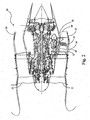
- FIG. 1 a top view of a fan duct lower bifurcation structure, 10, having an airstream cooling duct, 11, beginning upstream at a duct inlet, 12, and extending from there in this structure over a portion of its length downstream to an exit location to extend through a portion of the interior of bifurcation structure 10.
- Airstream 13 flows about, and then past, those tubes to reach an exit, 16, of duct 11 at its downstream end which has an exit cross sectional area that is controlled in magnitude by an exit flap, 16'.
- Entrance flap 12' can be selectively rotated forcibly inward or outward from the position thereof shown in Figure 1
- exit flap 16' can be selectively rotated forcibly inward or outward from the position thereof shown in that figure, by angle positioning motor, 17, causing a proportional linkage arrangement, 17' to correspondingly move these flaps, and the linkage components, about pins shown in bold dark circles and about the shaft coupled to that motor.
- entrance flap 12' can be so selectively rotated
- exit flap 16' can be so selectively rotated, by a corresponding one a pair of angle positioning motors, 17" and 17"', directly coupled thereto by corresponding shafts.
- flap 12' may be omitted.
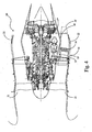
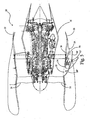
- Bifurcation structure 10 is positioned between the bottom of the wall of an engine core cowling, 18, and the bottom of the wall of an outer cowling, 19, of the engine pod for a turbofan engine, 20, as indicated in the partially cut away views shown in Figures 2 and 3 in which only a portion of outer cowling 19 is shown. Shown in turbofan engine 20 among other components is the fan, 21, and the fan duct nozzle, 22, with the fan duct extending therebetween.
- Figure 2 provides a representation of fan duct lower bifurcation structure 10 including airstream duct 11 with flaps 12' and 16' to be operated by angle positioning actuator or motor 17 directing proportional linkage arrangement 17'.
- Figure 3 alternatively provides a representation of fan duct lower bifurcation structure 10 including airstream duct 11 with flaps 12' and 16' to be directly operated by angle positioning actuators or motors 17" and 17"', respectively.
- Figure 4 shows a lengthened bifurcation structure, 10', extending past fan duct nozzle 22, and so outside of the turbofan engine fan duct into the atmosphere, and so fan duct nozzle 22 is configured to be capable of closing against, or nearly closing against, the wall of structure 10' to close, or nearly close, off the fan duct.
- duct structure 11 can be provided again with its input 12 in the fan airstream but then extending either through outer cowling 18, as in Figure 5 , or through engine core cowling 19 to extend through a portion of the engine compartment about which core cowling 19 is provided and back out of core cowling 19 to the atmosphere as shown in Figure 6 .
- Outer cowling 19 is shown in full cross section in Figures 5 and 6 .
- Ducts 11 in each of these figures are shown with exit flap 16' present and operated by angle positioning actuator or motor 17"' to control the amount of exit 16 that is open to the atmosphere during engine operation.
- flap 16' This control of flap 16' by a suitable controller (not shown) sets the degree of cooling of the oil in tubes 15 of air and oil heat exchanger 14 and the amount of thrust recovery.
- Devices other than flaps can be used to selectively reduce the area of exit opening 16 such as a variable area nozzle.
- a duct entrance opening flap, or other entrance opening selective opening area actuator can be provided at duct opening 12 in the ducts of Figures 5 and 6 .
- entrance opening flap, or other entrance opening selective opening area actuator can be provided at duct opening 12 in the ducts of Figures 5 and 6 .
Landscapes
- Engineering & Computer Science (AREA)
- Mechanical Engineering (AREA)
- General Engineering & Computer Science (AREA)
- Chemical & Material Sciences (AREA)
- Combustion & Propulsion (AREA)
- Physics & Mathematics (AREA)
- Fluid Mechanics (AREA)
- Structures Of Non-Positive Displacement Pumps (AREA)
- Incineration Of Waste (AREA)
Claims (14)
- Turbofantriebwerk mit einem Wärmeaustauschsystem für den Einsatz in Schmierungssystemen einer Turbofantriebwerk-Ausrüstung, in denen ein Schmierstoff zur Bereitstellung ausgewählter Betriebsvorgänge verwendet wird, wobei das Wärmeaustauschsystem Luft und Schmierstoff-Wärmeaustauscher zur Kühlung des Schmierstoffes mit selektiv variablen Raten in Lüfterströmen bereitstellt, auftretend im Inneren eines Motorlüfterkanals, der sich zwischen dem Turbofan-Motorlüfter (21) und einer Lüfterkanaldüse (22) erstreckt, dabei umfasst das System:einen Kühlkanal (11), der sich zumindest durch einen Abschnitt einer Stromstruktur erstreckt, welcher für den Zugang zu den Lüfterströmen während des Gebrauchs positioniert ist, wobei der Kühlkanal (11) eine Eingangsöffnung (12) zu den Lüfterströmen des Turbofantriebwerkes auf einer stromaufwärtigen Seite und eine Austrittsöffnung (16) auf einer stromabwärtigen Seite aufweist;eine bewegliche Eingangsklappe (12'), angeordnet auf der stromaufwärtigen Seite des Kühlkanals (11), so dass die bewegliche Eingangsklappe (12') in geschlossener Position mindestens einen Abschnitt der Eintrittsöffnung (12) abdeckt, und in offener Position Luftströmung durch den Kühlkanal (11) ermöglicht;eine bewegliche Austrittsklappe (16'), angeordnet auf der stromabwärtigen Seite des Kühlkanals (11), so dass die bewegliche Austrittsklappe (16') in geschlossener Position mindestens einen Abschnitt der Austrittsöffnung (16) abdeckt, und in offener Position Luftströmung durch den Kühlkanal (11) ermöglicht; undeinen Wärmeaustauscherkern (14), bereitgestellt im Kühlkanal (11) zwischen Eintritts- undAustrittsöffnungen (12, 16) davon und mit einer Vielzahl von Durchgangsstrukturen (15) darin, über welche Luft eintreten kann, um dort hindurch zu strömen, wobei die Durchgangsstrukturen (15) an eine Eingangsleitung an einem Ende davon gekuppelt und an eine Ausgangsleitung an einem gegenüberliegenden Ende davon gekuppelt sind, um die Bereitstellung undEntfernung des Schmierstoffes in den Innenräumen der Durchgangsstrukturen (15) in den Innenbereichen der Eingangs- und Ausgangsleitungen zu ermöglichen; wobei die Stromstruktur ausgewählt wird aus a) einem Abschnitt einer Triebwerkskernverkleidung (18) über dem Motorraum des Turbofantriebwerks (20), mit dem Ende des Kühlkanals (11) darüber oder außerhalb des Endes der Lüfterkanaldüse (22) des Turbofantriebwerks (20) angeordnet, und b) einem Abschnitt der äußeren Verkleidung (19) einer Gondel des Turbofantriebwerks (20).
- Turbofantriebwerk des Anspruchs 1, wobei die Stromstruktur ein Abschnitt einer Triebwerkskernverkleidung (18) über dem Motorraum des Turbofantriebwerks (20) ist, mit dem Ende des Kühlkanals (11) darüber oder außerhalb des Endes der Lüfterkanaldüse (22) des Turbofantriebwerks (20) angeordnet, und der Kühlkanal (11) sich durch die Triebwerkskernverkleidung (18) an einer ersten Stelle erstreckt, um sich von dort durch einen Abschnitt des Motorraumes, über welchem die Triebwerkskernverkleidung (18) vorgesehen ist, und sich dann nochmal durch die Triebwerkskernverkleidung (18) an einer zweiten Stelle zu erstrecken.
- Turbofantriebwerk des Anspruchs 1 und 2, wobei die Eingangsklappe (12') an der Kühlkanal-Eintrittsöffnung (12) angebracht ist, und drehbar um eine Achse ist, im Wesentlichen parallel zu einer Achse, welche gegenüberliegende Kanten der Kühlkanal-Austrittsöffnung (16) schneidet.
- Turbofantriebwerk jedes vorhergehenden Anspruchs, wobei die Austrittsklappe (16') an der Kühlkanal-Austrittsöffnung (16) angebracht ist, und drehbar um eine Achse ist, im Wesentlichen parallel zu einer Achse, welche gegenüberliegende Kanten der Kühlkanal-Austrittsöffnung (16) schneidet.
- Turbofantriebwerk jedes vorhergehenden Anspruchs, ferner einen ersten Klappen-Aktuator (17) umfassend, angeschlossen an eine mechanische Verbindung (17'), die auch angeschlossen ist an beide Eintritts- und Austrittsklappen (12', 16'), um so dem ersten Klappen-Aktuator (17) zu ermöglichen, Eintritts- und Austrittsklappen (12', 16') zu zwingen, die Positionen zu verändern.
- Turbofantriebwerk des Anspruchs 5, wobei die Eintrittsklappe (12') mittels der mechanischen Verbindung (17') geöffnet wird, um mehr Querschnittsfläche der Eintrittsöffnung (12) freizulegen, als durch das Öffnen der Austrittsklappe (16') mittels der mechanischen Verbindung (17') Querschnittsfläche der Austrittsöffnung (16) freigelegt wird.
- Turbofantriebwerk des Anspruchs 5 oder 6, wobei die Eintrittsklappe (12') durch die mechanische Verbindung (17') über der Eintrittsöffnung (12) geschlossen wird, wenn die Austrittsklappe (16') durch die mechanische Verbindung (17') über der Austrittsöffnung (16) geschlossen wird.
- Turbofantriebwerk jedes vorhergehenden Anspruchs, ferner umfassend einen ersten Klappen-Aktuator (17"), der mit der Eintrittsklappe (12') verbunden ist, so dass es dem ersten Klappen-Aktuator (17 ") ermöglicht wird, die Eintrittsklappe (12') zu zwingen, die Positionen zu verändern, und ferner umfassend einen zweiten Klappen-Aktuator (17"'), der mit der Austrittsklappe (16') verbunden ist, so dass es dem zweiten Klappen Aktuator (17"') ermöglicht wird, die Austrittsklappe (16') zu zwingen, die Positionen zu verändern.
- Turbofantriebwerk des Anspruchs 8, wobei die Eintrittsklappe (12') mittels des ersten Klappen-Aktuators (17") geöffnet wird, um mehr Querschnittsfläche der Eintrittsöffnung (12) freizulegen, als durch das Öffnen der Austrittsklappe (16') mittels des zweiten Klappen-Aktuators (17"') Querschnittsfläche der Austrittsöffnung (16) freigelegt wird.
- Turbofantriebwerk des Anspruchs 8 oder 9, wobei die Eintrittsklappe (12') durch den ersten Klappen-Aktuator (17") über der Eintrittsöffnung (12) geschlossen wird, wenn die Austrittsklappe (16') durch den zweiten Klappen-Aktuator (17"') über der Austrittsöffnung (16) geschlossen wird.
- Verfahren zur Kühlung von Schmieröl, vorgesehen in einem Schmierungssystem für ein Turbofantriebwerk (20) zur Schmierung beweglicher Teile, mit selektiv variablen Raten in Lüfterströmen in einem Lüfterkanal, bereitstellt durch den Fan des Turbofantriebwerks (20) während des Betriebsvorganges des Turbofantriebwerks (20) unter Einsatz eines Wärmeaustauschers (14), untergebracht in einem Kühlkanal (11), der sich durch mindestens einen Abschnitt einer Stromstruktur erstreckt, das heißt, positioniert für den Zugang zu den Lüfterströmen auf der stromaufwärtigen Seite einer Motorlüfterkanalwand, zur Bereitstellung von Luft und Schmieröl-Wärmeaustauscher, um so Luftkühlung des Schmieröls bereitzustellen, wobei der Kühlkanal (11) eine Kanaleintrittsöffnung (12) zu den Lüfterströmen des Turbofantriebwerks (20) hat und ferner eine Kanalaustrittsöffnung (16) mit einer beweglichen Austrittsklappe (16'), um zumindest teilweise einen Abschnitt dieser Austrittsöffnung (16) abzudecken, und eine bewegliche Eintrittsklappe (12'), vorgesehen an der Eintrittsöffnung (12), um zumindest teilweise einen Abschnitt der Eintrittsöffnung (12') abzudecken, wobei das Verfahren umfasst:Erzwingung, dass das Schmieröl die beweglichen Teile schmiert und auch durch den Wärmeaustauscher (14) durchläuft, der einen Kern mit einer Vielzahl von Durchgangsstrukturen (15), über welche Luft strömen kann, darin hat, wobei die Durchgangsstrukturen (15) an eine Eingangsleitung an einem Ende davon gekuppelt und an eine Ausgangsleitung an einem gegenüberliegenden Ende davon gekuppelt sind, um die Bereitstellung und Entfernung des Schmieröls in den Innenräumen der Durchgangsstrukturen (15) in den Innenbereichen der Eingangs- und Ausgangsleitungen zu ermöglichen;Öffnung der Austrittsklappe (16'), um einen ausgewählten Abschnitt der Austrittsöffnung (16) freizugeben; undÖffnung der Eintrittsklappe (12'), um einen ausgewählten Abschnitt der Eintrittsöffnung (12) freizugeben, um dadurch einen Teil des Lüfterstroms zum Kühlkanal (11) hereinzulassen; wobei die Stromstruktur ausgewählt wird aus a) einem Abschnitt der Triebwerkskernverkleidung (18) über dem Motorraum des Turbofantriebwerks (20), mit dem Ende des Kühlkanals (11) darüber oder außerhalb des Endes der Lüfterkanaldüse (22) des Turbofantriebwerks (20) angeordnet, und b) einem Abschnitt der äußeren Verkleidung (19) einer Gondel des Turbofantriebwerks (20).
- Verfahren des Anspruchs 11, wobei der ausgewählte Abschnitt der Austrittsöffnung (16), der freigelegt wird, kleiner als der freigelegte Abschnitt der Eintrittsöffnung (12) ist.
- Verfahren des Anspruchs 11 oder 12, wobei die Austrittsöffnung (16) darüber oder außerhalb des Endes der Lüfterkanaldüse angeordnet ist.
- Verfahren des Anspruchs 11, 12 oder 13 ferner umfassend im Wesentlichen das Schließen der Austrittsklappe, um die Austrittsöffnung abzudecken und das Schließen der Eintrittsklappe, um die Eintrittsöffnung abzudecken.
Applications Claiming Priority (1)
| Application Number | Priority Date | Filing Date | Title |
|---|---|---|---|
| US11/650,825 US7810311B2 (en) | 2006-07-06 | 2007-01-08 | Cooling exchanger ducts |
Publications (3)
| Publication Number | Publication Date |
|---|---|
| EP1944475A2 EP1944475A2 (de) | 2008-07-16 |
| EP1944475A3 EP1944475A3 (de) | 2010-11-03 |
| EP1944475B1 true EP1944475B1 (de) | 2015-08-12 |
Family
ID=39263291
Family Applications (1)
| Application Number | Title | Priority Date | Filing Date |
|---|---|---|---|
| EP08250063.8A Ceased EP1944475B1 (de) | 2007-01-08 | 2008-01-08 | Wärmeaustauschsystem |
Country Status (1)
| Country | Link |
|---|---|
| EP (1) | EP1944475B1 (de) |
Cited By (3)
| Publication number | Priority date | Publication date | Assignee | Title |
|---|---|---|---|---|
| WO2021034359A3 (en) * | 2019-05-15 | 2021-05-06 | Raytheon Technologies Corporation | Multi-mode heat rejection system |
| EP3851659B1 (de) * | 2020-01-15 | 2022-08-17 | Airbus Operations (S.A.S.) | Kälteregelventil für ein wärmetauschersystem eines flugzeugantriebssystems |
| US11846237B2 (en) | 2017-01-19 | 2023-12-19 | Rtx Corporation | Gas turbine engine with intercooled cooling air and dual towershaft accessory gearbox |
Families Citing this family (33)
| Publication number | Priority date | Publication date | Assignee | Title |
|---|---|---|---|---|
| US8127828B2 (en) * | 2006-03-17 | 2012-03-06 | United Technologies Corporation | Air-oil heat exchanger |
| DE102009011452A1 (de) | 2009-03-03 | 2010-09-09 | Rolls-Royce Deutschland Ltd & Co Kg | Verfahren zur Herstellung eines Ejektor-Düsen-Rohrs |
| FR2955897B1 (fr) * | 2010-01-29 | 2013-08-16 | Snecma | Procede et circuit simplifies de ventilation d'equipements d'un turboreacteur |
| FR2955896B1 (fr) * | 2010-01-29 | 2013-08-16 | Snecma | Procede et circuit de ventilation d'equipements d'un turboreacteur |
| US8961114B2 (en) * | 2010-11-22 | 2015-02-24 | General Electric Company | Integrated variable geometry flow restrictor and heat exchanger |
| DE102011011879A1 (de) * | 2011-02-21 | 2012-08-23 | Airbus Operations Gmbh | Kühllufteinlass, Triebwerkzapfluftsystem und Verfahren zum Betreiben eines Kühllufteinlasses |
| DE102011101342A1 (de) * | 2011-05-12 | 2012-11-15 | Rolls-Royce Deutschland Ltd & Co Kg | Fluggasturbinentriebwerk mit Ölkühler in der Triebwerksverkleidung |
| US9260191B2 (en) | 2011-08-26 | 2016-02-16 | Hs Marston Aerospace Ltd. | Heat exhanger apparatus including heat transfer surfaces |
| US20150361891A1 (en) | 2013-03-15 | 2015-12-17 | United Technologies Corporation | Air-Oil Heat Exchangers with Minimum Bypass Flow Pressure Loss |
| FR3014080A1 (fr) * | 2014-04-22 | 2015-06-05 | Aircelle Sa | Ensemble propulsif pour aeronef |
| US10066550B2 (en) * | 2014-05-15 | 2018-09-04 | Rolls-Royce North American Technologies, Inc. | Fan by-pass duct for intercooled turbo fan engines |
| US10731560B2 (en) | 2015-02-12 | 2020-08-04 | Raytheon Technologies Corporation | Intercooled cooling air |
| US10371055B2 (en) | 2015-02-12 | 2019-08-06 | United Technologies Corporation | Intercooled cooling air using cooling compressor as starter |
| US11808210B2 (en) | 2015-02-12 | 2023-11-07 | Rtx Corporation | Intercooled cooling air with heat exchanger packaging |
| US10830148B2 (en) | 2015-04-24 | 2020-11-10 | Raytheon Technologies Corporation | Intercooled cooling air with dual pass heat exchanger |
| US10480419B2 (en) | 2015-04-24 | 2019-11-19 | United Technologies Corporation | Intercooled cooling air with plural heat exchangers |
| US10221862B2 (en) | 2015-04-24 | 2019-03-05 | United Technologies Corporation | Intercooled cooling air tapped from plural locations |
| US10100739B2 (en) | 2015-05-18 | 2018-10-16 | United Technologies Corporation | Cooled cooling air system for a gas turbine engine |
| US10794288B2 (en) | 2015-07-07 | 2020-10-06 | Raytheon Technologies Corporation | Cooled cooling air system for a turbofan engine |
| DE102015224701A1 (de) * | 2015-12-09 | 2017-06-14 | Rolls-Royce Deutschland Ltd & Co Kg | Fluggasturbine mit variabler Austrittsdüse eines Nebenstromkanals |
| US10443508B2 (en) | 2015-12-14 | 2019-10-15 | United Technologies Corporation | Intercooled cooling air with auxiliary compressor control |
| US10669940B2 (en) | 2016-09-19 | 2020-06-02 | Raytheon Technologies Corporation | Gas turbine engine with intercooled cooling air and turbine drive |
| US10794290B2 (en) | 2016-11-08 | 2020-10-06 | Raytheon Technologies Corporation | Intercooled cooled cooling integrated air cycle machine |
| US10550768B2 (en) | 2016-11-08 | 2020-02-04 | United Technologies Corporation | Intercooled cooled cooling integrated air cycle machine |
| US10961911B2 (en) | 2017-01-17 | 2021-03-30 | Raytheon Technologies Corporation | Injection cooled cooling air system for a gas turbine engine |
| US10577964B2 (en) | 2017-03-31 | 2020-03-03 | United Technologies Corporation | Cooled cooling air for blade air seal through outer chamber |
| US10711640B2 (en) | 2017-04-11 | 2020-07-14 | Raytheon Technologies Corporation | Cooled cooling air to blade outer air seal passing through a static vane |
| US10738703B2 (en) | 2018-03-22 | 2020-08-11 | Raytheon Technologies Corporation | Intercooled cooling air with combined features |
| US10808619B2 (en) | 2018-04-19 | 2020-10-20 | Raytheon Technologies Corporation | Intercooled cooling air with advanced cooling system |
| US10830145B2 (en) | 2018-04-19 | 2020-11-10 | Raytheon Technologies Corporation | Intercooled cooling air fleet management system |
| US10718233B2 (en) | 2018-06-19 | 2020-07-21 | Raytheon Technologies Corporation | Intercooled cooling air with low temperature bearing compartment air |
| US11255268B2 (en) | 2018-07-31 | 2022-02-22 | Raytheon Technologies Corporation | Intercooled cooling air with selective pressure dump |
| FR3089248B1 (fr) * | 2018-12-03 | 2020-11-20 | Safran Aircraft Engines | Ensemble moteur pour aéronef présentant un support de système d’échangeur air-huile a fixation optimisée |
Family Cites Families (7)
| Publication number | Priority date | Publication date | Assignee | Title |
|---|---|---|---|---|
| DE1019866B (de) * | 1940-06-24 | 1957-11-21 | Bayerische Motoren Werke Ag | Anordnung des Schmierstoffkuehlers eines mit einem die Arbeitsluft foerdernden Geblaese versehenen Strahltriebwerkes |
| GB750200A (en) | 1953-12-30 | 1956-06-13 | Armstrong Siddeley Motors Ltd | Improvements relating to ducted-fan, turbo-jet engines |
| GB9027782D0 (en) * | 1990-12-21 | 1991-02-13 | Rolls Royce Plc | Heat exchanger apparatus |
| CA2226424C (en) | 1995-07-07 | 2007-01-23 | Dimitrie Negulescu | Aircraft gas turbine engine with a liquid-air heat exchanger |
| FR2788308A1 (fr) * | 1999-01-07 | 2000-07-13 | Snecma | Dispositif de refroidissement d'un reducteur de vitesse de turbomachine |
| US7454894B2 (en) * | 2004-12-07 | 2008-11-25 | United Technologies Corporation | Supplemental oil cooler airflow for gas turbine engine |
| US7765788B2 (en) | 2006-07-06 | 2010-08-03 | United Technologies Corporation | Cooling exchanger duct |
-
2008
- 2008-01-08 EP EP08250063.8A patent/EP1944475B1/de not_active Ceased
Cited By (6)
| Publication number | Priority date | Publication date | Assignee | Title |
|---|---|---|---|---|
| US11846237B2 (en) | 2017-01-19 | 2023-12-19 | Rtx Corporation | Gas turbine engine with intercooled cooling air and dual towershaft accessory gearbox |
| WO2021034359A3 (en) * | 2019-05-15 | 2021-05-06 | Raytheon Technologies Corporation | Multi-mode heat rejection system |
| US11378009B2 (en) | 2019-05-15 | 2022-07-05 | Raytheon Technologies Corporation | Multi-mode heat rejection system for a gas turbine engine |
| EP3969730A4 (de) * | 2019-05-15 | 2023-06-21 | Raytheon Technologies Corporation | Multimodales wärmeabstosssystem |
| EP4653686A3 (de) * | 2019-05-15 | 2026-03-04 | RTX Corporation | Multimodales wärmeabweisungssystem |
| EP3851659B1 (de) * | 2020-01-15 | 2022-08-17 | Airbus Operations (S.A.S.) | Kälteregelventil für ein wärmetauschersystem eines flugzeugantriebssystems |
Also Published As
| Publication number | Publication date |
|---|---|
| EP1944475A2 (de) | 2008-07-16 |
| EP1944475A3 (de) | 2010-11-03 |
Similar Documents
| Publication | Publication Date | Title |
|---|---|---|
| EP1944475B1 (de) | Wärmeaustauschsystem | |
| EP1876328B1 (de) | Wärmetauschersystem in einem Fantriebwerk | |
| EP1882824B1 (de) | Doppelter Einlasskanal eines Schmiermittelkühltauschers | |
| CN114060474B (zh) | 涡轮机发动机的齿轮箱效率等级 | |
| EP1930557B1 (de) | Turbinentriebwerk mit integriertem Generator mit gemeinsamem Schmierungssystem | |
| EP1923542B1 (de) | Voneinander abhängige Schmiersysteme | |
| EP1835128B1 (de) | Ausfahrbarer Wärmetauscher für ein Schmierstoffsystem eines Turbofantriebwerks | |
| EP1857638B1 (de) | Wärmeregelungssystem für Mantelstromtriebwerke | |
| EP3483414B1 (de) | Gasturbinentriebwerk mit einem luft-öl-wärmetauscher | |
| EP2971664B1 (de) | Getriebeturbofanmotor und kühlverfahren dafür | |
| EP2546472A2 (de) | Wärmemanagementsystem für Gasturbinenmotor | |
| US20110179767A1 (en) | Cooling device for aircraft propeller | |
| CN117125258B (zh) | 飞机辅助动力装置系统 | |
| EP4336032B1 (de) | Wärmeverwaltungssystem für ein flugzeug | |
| US20110182723A1 (en) | Turbomachine aircraft propeller |
Legal Events
| Date | Code | Title | Description |
|---|---|---|---|
| PUAI | Public reference made under article 153(3) epc to a published international application that has entered the european phase |
Free format text: ORIGINAL CODE: 0009012 |
|
| AK | Designated contracting states |
Kind code of ref document: A2 Designated state(s): AT BE BG CH CY CZ DE DK EE ES FI FR GB GR HR HU IE IS IT LI LT LU LV MC MT NL NO PL PT RO SE SI SK TR |
|
| AX | Request for extension of the european patent |
Extension state: AL BA MK RS |
|
| RAP1 | Party data changed (applicant data changed or rights of an application transferred) |
Owner name: UNITED TECHNOLOGIES CORPORATION |
|
| PUAL | Search report despatched |
Free format text: ORIGINAL CODE: 0009013 |
|
| AK | Designated contracting states |
Kind code of ref document: A3 Designated state(s): AT BE BG CH CY CZ DE DK EE ES FI FR GB GR HR HU IE IS IT LI LT LU LV MC MT NL NO PL PT RO SE SI SK TR |
|
| AX | Request for extension of the european patent |
Extension state: AL BA MK RS |
|
| 17P | Request for examination filed |
Effective date: 20110503 |
|
| AKX | Designation fees paid |
Designated state(s): DE GB |
|
| GRAP | Despatch of communication of intention to grant a patent |
Free format text: ORIGINAL CODE: EPIDOSNIGR1 |
|
| INTG | Intention to grant announced |
Effective date: 20150424 |
|
| GRAS | Grant fee paid |
Free format text: ORIGINAL CODE: EPIDOSNIGR3 |
|
| GRAA | (expected) grant |
Free format text: ORIGINAL CODE: 0009210 |
|
| AK | Designated contracting states |
Kind code of ref document: B1 Designated state(s): DE GB |
|
| REG | Reference to a national code |
Ref country code: GB Ref legal event code: FG4D |
|
| REG | Reference to a national code |
Ref country code: DE Ref legal event code: R096 Ref document number: 602008039475 Country of ref document: DE |
|
| REG | Reference to a national code |
Ref country code: DE Ref legal event code: R097 Ref document number: 602008039475 Country of ref document: DE |
|
| PLBE | No opposition filed within time limit |
Free format text: ORIGINAL CODE: 0009261 |
|
| STAA | Information on the status of an ep patent application or granted ep patent |
Free format text: STATUS: NO OPPOSITION FILED WITHIN TIME LIMIT |
|
| 26N | No opposition filed |
Effective date: 20160513 |
|
| REG | Reference to a national code |
Ref country code: DE Ref legal event code: R082 Ref document number: 602008039475 Country of ref document: DE Representative=s name: SCHMITT-NILSON SCHRAUD WAIBEL WOHLFROM PATENTA, DE |
|
| REG | Reference to a national code |
Ref country code: DE Ref legal event code: R082 Ref document number: 602008039475 Country of ref document: DE Representative=s name: SCHMITT-NILSON SCHRAUD WAIBEL WOHLFROM PATENTA, DE Ref country code: DE Ref legal event code: R081 Ref document number: 602008039475 Country of ref document: DE Owner name: UNITED TECHNOLOGIES CORP. (N.D.GES.D. STAATES , US Free format text: FORMER OWNER: UNITED TECHNOLOGIES CORPORATION, HARTFORD, CONN., US |
|
| PGFP | Annual fee paid to national office [announced via postgrant information from national office to epo] |
Ref country code: GB Payment date: 20201218 Year of fee payment: 14 |
|
| PGFP | Annual fee paid to national office [announced via postgrant information from national office to epo] |
Ref country code: DE Payment date: 20201217 Year of fee payment: 14 |
|
| REG | Reference to a national code |
Ref country code: DE Ref legal event code: R119 Ref document number: 602008039475 Country of ref document: DE |
|
| REG | Reference to a national code |
Ref country code: DE Ref legal event code: R081 Ref document number: 602008039475 Country of ref document: DE Owner name: RAYTHEON TECHNOLOGIES CORPORATION (N.D.GES.D.S, US Free format text: FORMER OWNER: UNITED TECHNOLOGIES CORP. (N.D.GES.D. STAATES DELAWARE), FARMINGTON, CONN., US |
|
| GBPC | Gb: european patent ceased through non-payment of renewal fee |
Effective date: 20220108 |
|
| PG25 | Lapsed in a contracting state [announced via postgrant information from national office to epo] |
Ref country code: GB Free format text: LAPSE BECAUSE OF NON-PAYMENT OF DUE FEES Effective date: 20220108 Ref country code: DE Free format text: LAPSE BECAUSE OF NON-PAYMENT OF DUE FEES Effective date: 20220802 |