EP1944698A2 - Agencements, procédés et dispositifs de transmission de données entre un dispositif de commande et un appareil électrique - Google Patents
Agencements, procédés et dispositifs de transmission de données entre un dispositif de commande et un appareil électrique Download PDFInfo
- Publication number
- EP1944698A2 EP1944698A2 EP07117526A EP07117526A EP1944698A2 EP 1944698 A2 EP1944698 A2 EP 1944698A2 EP 07117526 A EP07117526 A EP 07117526A EP 07117526 A EP07117526 A EP 07117526A EP 1944698 A2 EP1944698 A2 EP 1944698A2
- Authority
- EP
- European Patent Office
- Prior art keywords
- type
- connection
- usb
- interface
- logical
- Prior art date
- Legal status (The legal status is an assumption and is not a legal conclusion. Google has not performed a legal analysis and makes no representation as to the accuracy of the status listed.)
- Granted
Links
Images

Classifications
-
- G—PHYSICS
- G06—COMPUTING OR CALCULATING; COUNTING
- G06F—ELECTRIC DIGITAL DATA PROCESSING
- G06F13/00—Interconnection of, or transfer of information or other signals between, memories, input/output devices or central processing units
- G06F13/38—Information transfer, e.g. on bus
- G06F13/40—Bus structure
- G06F13/4004—Coupling between buses
- G06F13/4022—Coupling between buses using switching circuits, e.g. switching matrix, connection or expansion network
-
- G—PHYSICS
- G06—COMPUTING OR CALCULATING; COUNTING
- G06F—ELECTRIC DIGITAL DATA PROCESSING
- G06F2213/00—Indexing scheme relating to interconnection of, or transfer of information or other signals between, memories, input/output devices or central processing units
- G06F2213/40—Bus coupling
- G06F2213/4004—Universal serial bus hub with a plurality of upstream ports
Definitions
- the present invention relates to an arrangement for the transmission of data between a control device and an electrical device, which provides a plurality of logical devices via a connection.
- USB Universal Serial Bus
- peripheral device such as in the form of a printer or a computer mouse.
- USB Universal Serial Bus
- electrical devices such as in the form of said peripherals, nowadays often have a USB port, via which these electrical devices can be connected to a computer.
- USB allows an electrical device to provide multiple logical devices through one port.
- USB Universal Serial Bus Specification; Compaq, Intel, Microsoft, NEC; Revision 1.1; September 23, 1998
- an electrical device in the form of a USB device or "USB device” several logical devices in the form of so-called interfaces. This happens as part of the configuration of the relevant USB device.
- an interface refers in each case to a single functionality that the USB device offers to the control device in the form of a USB host.
- the present invention has for its object to provide a flexible and versatile arrangement of the type mentioned.
- an arrangement for the transmission of data between a control device and an electrical device, which provides a plurality of logical device via a connection wherein the arrangement comprises a second control device and the electrical device via interfaces with the control devices connecting connection device whose first interface is connected to the transfer of data associated with a logical device of the first type data with the control device whose second interface is connected to the transmission of a logical device of the second type associated data with the second control device and their third interface for transmitting data associated with a respective logical device of the first or second type associated with the connection of the electrical device.
- the data transmitted between the control device and the electrical device may be, on the one hand, control data, such as the registration of the electrical device with the control device or the control of the functionality of the electrical device by the control device.
- the data may also be transmission data, for example in the form of measurement data acquired by the electrical device.
- the data transmitted between the electrical device and the control device will include both control and transmission data.
- the transmission of the data can take place both unidirectionally, ie either exclusively from the control device to the electrical device or from the electrical device to the control device, or else bidirectionally. Therefore, the phrase "transmission between" in the context of the present invention includes the sending and / or receiving of data.
- the control device can be given for example by a computer or a processor;
- the electrical device may in principle be any type of device, e.g. one of the aforementioned peripherals, act. In this case, it is not decisive that the device designated as a control device actually performs a controlling function, but that a transfer of data takes place between the control device and the electrical device.
- the arrangement according to the invention is advantageous because it makes it possible to simultaneously connect an electrical device to two different control devices.
- the arrangement comprises a connection device, which is connected in each case via an interface with the control device, the second control device and the connection of the electrical device.
- the first interface is used for the transmission of data associated with a logical device of the first type between the connection device and the control device. This means that such data associated with a logical device of the first kind, i. a logical device to be provided to the control device can be transmitted via the first interface between the connection device and the control device.
- the second interface of the connection device for the transmission of a logical device of the second kind, ie a logical device to be provided to the second control device, assigned Data connected to the second control device.
- a logical device of the second kind ie a logical device to be provided to the second control device, assigned Data connected to the second control device.
- connection device Via the third interface of the connection device, data associated with a logical device of the first type as well as a second type of logical device can be transmitted between the connection device and the connection of the electrical device. This is advantageously done via a common physical connection.
- connection of the electrical device depending on the provided via the connection wired or wireless interface be pronounced in different ways. Examples of corresponding interfaces are USB or Bluetooth.
- the arrangement according to the invention also offers the advantage that it is preferably not necessary to make adjustments on the part of the electrical device or on the part of the control devices. This is true even though the electrical device is connected to both the control device and the second control device with respect to at least one logical device, i. provides the respective logical devices of the respective control device.
- the present invention and its preferred developments described below are basically also applicable to more than two control devices.
- the connection device by means of the connection device, the logical devices of an electrical device to three or more Tax facilities are split.
- an inventive division of the logical devices of an electrical device to a plurality of control devices is particularly advantageous if one of the control devices to which the electrical device is connected, is not able to all provided by the electrical device available logical To operate devices.
- a division of the logical devices of the electrical device to a plurality of control devices is required in order to connect all logical devices of the electrical device in each case to a control device can.
- the arrangement according to the invention is designed such that the interfaces are USB (Universal Serial Bus) interfaces, wherein the electrical device is designed as a USB device, the port as a USB port and the control devices as USB hosts are, and the connection device to the electrical device as a USB host and compared to the control devices as a USB device is formed.
- USB Universal Serial Bus
- the connection device is the electrical device in the form of the USB device as a USB host.
- the connection device serves the two control devices in the form of USB hosts as a USB device.
- connection device is preferably transparent to the electrical device and the control devices in that changes in the components involved due to the transmission of data for at least one logical device of the electrical device between the control device and the electrical device or between the second control device and the electrical device are not required.
- the connection device thus advantageously makes it possible for the control devices connected to the connection device via the first or the second interface in each case only a subset of the logical devices of the electrical device connected to the connection device via the third interface are visible.
- the logical devices are USB interfaces of the electrical device.
- USB interfaces are already defined and widely used logical devices of an electrical device in the form of a USB device. These logical devices can now be physically separated from multiple control devices in the form of USB hosts.
- the arrangement according to the invention can also be designed such that the electrical device is a radio module.
- radio modules often have other interfaces, for example in the form of a USB interface, in addition to a wireless radio interface.
- This interface can serve, for example, to transmit data relating to the course of the radio module, for example in the form of so-called diagnostic data or traces, from the radio module to a control device in the form of a computer for subsequent evaluation.
- the radio module via the USB interface can be controlled by a control device, however, perform its function as a communication interface to a mobile network substantially independent of the control device.
- the control unit controlling the radio module is not for processing according to the invention, the possibility of distributing the logical devices of the electrical device in the form of the radio module to a plurality of control devices, ie to provide these logical devices several control devices available. This allows a transmission of data, each specific to the logical device in question, in each case between the radio module and a first control device or the radio module and a second control device.
- the invention further relates to a method for transmitting data between a control device and an electrical device, which provides a plurality of logical devices via a connection.
- a method for transferring data between a control device and an electrical device which provides a plurality of logical devices via a connection, in which after connecting the electrical device via the connection to a connection device and connecting the connection Device to the control device and to a second control device associated with a logical device of the first type data between a first interface of the connection device and the control device are transmitted, a logical device of the second type associated data between a second interface of the connection Device and the second control device are transmitted and each associated with a logical device of the first or second type data between a third interface of the connection device and the connection of the electrical device.
- the steps of the method according to the invention can also take place in a different order; It is essential that there is a transmission of data between the electrical device and the control devices, but not the order of these transmissions.
- the inventive method is preferred because it allows data associated with a first type logical device to be transferred between a first interface of the connection device and the control device, data associated with a second type logical device between a second interface of the connection device and the second control device.
- both data assigned to a logical device of the first type as well as a logical device of the second type are transmitted between a third interface of the connection device and the connection of the electrical device.
- the inventive method is designed such that is used as an electrical device, a USB device with a port in the form of a USB port and control devices USB host or are, wherein the connection device relative to the electrical device as a USB Host and opposite to the control facilities serves as a USB device.
- This embodiment of the method according to the invention is preferred, since it makes it possible to connect an electrical device in the form of a USB device simultaneously to two control devices in the form of USB hosts, that data assigned to a logical device of the first type via the connection device be transmitted between the electrical device and the control device during a logical Device of the second type associated data are transmitted via the second interface of the connection device between the electrical device and the second control device.
- the logical devices of the electrical device in the form of the USB device can each be provided to one of the two control devices for the purpose of transmitting data.
- the respective other logical devices for the respective control device are not visible.
- USB interfaces of the electrical device are used as logical devices. This offers the particular advantage that USB interfaces are the usual, widespread type of logical devices used in connection with USB devices.
- the method according to the invention can also be so pronounced that a radio module is used as the electrical device.
- This embodiment of the method according to the invention is preferred, as it makes it possible to simultaneously connect a radio module to a plurality of control devices, wherein data is assigned either between the radio module depending on whether it is associated with a first type logical device or a second type logical device and the control device or between the radio module and the second control device.
- the versatility of the usability of radio modules is further increased.
- the third interface, via which the connection of the radio module is connected to the connection device is generally not identical with the radio interface of the radio module.
- the invention further relates to a device for transmitting data between a control device and an electrical device, which provides a plurality of logical devices via a connection.
- the present invention has the object to provide a flexible and versatile device of the type mentioned.
- connection device for transferring data between a control device and an electrical device that provides a plurality of logical devices via a port, and between a second control device and the electrical device, the connection device with a data interface between the connection device and the control device, a second interface for the transmission of a logical device of the second type, data between the connection device and the second control device and associated with a first interface for the transmission of a first type logical device third interface for the transmission of a respective logical device of the first or second type associated data between the connection device and the connection of the electrical device.
- connection device is advantageous because it is for the transmission of data associated with a logical device of the first type data between the electrical device and the Control device and for transmission of a logical device of the second type associated data between the electrical device and the second control device is formed.
- connection device is preferably configured such that the interfaces are USB (Universal Serial Bus) interfaces and the connection device is designed as USB host with respect to the electrical device and as USB device with respect to the control devices.
- USB Universal Serial Bus
- connection device according to the invention and its preferred development will be apparent from the corresponding statements in connection with the arrangement according to the invention and the method according to the invention.
- the object underlying the present invention is furthermore achieved with regard to the arrangement by an arrangement for the transmission of data between a control device and an electrical device which provides at least one logical device via a connection of the first type, the device being an electrical device interconnection unit interfacing with the control means comprises a first type controller side interface for communicating data associated with a first or second type logical device between the connection unit and the control device, a device side interface of the first type for transmission associated with a logical device of the first kind Data between the connection unit and the first-type connector of the electrical apparatus, a second-type apparatus-side interface for transmitting the data between the connection unit and a second-type connector of the electrical apparatus and a second between the controller-side interface of the first type and the device-side interface Type arranged data converter.
- connection unit connecting the electrical device via interfaces with the control device.
- This has a control-device-side interface of the first type for transmitting data respectively associated with a logical device of the first or second type data between the connection unit and the control device.
- connection unit comprises a device-side interface of the first type for transmitting the data associated with a logical device of the first type between the connection unit and the connection of the first type of electrical device, and a device-side interface of the second type for transmitting data between the connection Unit and a connector of the second type of electrical device.
- the connection unit makes it possible to provide data transmitted via a second type interface to a control device in the form of at least one additional logical device.
- control device it is not necessary for the control device to have an interface of the second type at all, since the data transferred via the interface of the second type are presented to it as an additional logical device.
- the control device preferably a distinction of the logical device or the logical devices whose or their data are transmitted via the interface of the first type, and the data transmitted via the interface of the second type of electrical device is not required.
- the latter data appears to the control device to data advantageously associated with an additional logical device of the first type interface.
- the data converter arranged between the control-device-side interface and the device-side interface of the second type serves for the respective conversion of the data required depending on the transmission direction of the data.
- data transferred to the controller it carries conversion of the transmitted data from a format supported by the second-type device-side interface to a format supported by the controller-side interface of the first type or in the case of being transmitted to the electrical device
- Data performs conversion of the transferred data from a format supported by the controller-side interface of the first type into a format supported by the second-type device-side interface.
- a corresponding conversion may, for example, be a conversion of a protocol used on the controller-side interface of the first type into a protocol used on the device-side interface of the second type.
- data again includes any type of control or transmission data. To what extent and for which types of data a conversion is required depends on the specific interfaces of the first and second types used.
- the control-device-side interface of the first type and the device-side interface of the first type USB (Universal Serial Bus) interfaces wherein the electrical device is designed as a USB device, the first-type port as a USB port and the control device as a USB host, and the connection unit to the electrical device as USB host and opposite the control device is designed as a USB device.
- This embodiment of the arrangement according to the invention is preferred because it enables a second type of electrical device in the form of a USB device of the control device in the form of a USB host to be provided as a logical device of the USB device.
- a corresponding interface of the second type can additionally be registered as a logical device of the USB device in the USB host and addressed by this as well as the other logical devices of the electrical device and optionally controlled.
- the further arrangement according to the invention can also be designed such that the logical devices are USB interfaces of the electrical device.
- the logical devices are USB interfaces of the electrical device. This is advantageous because USB interfaces are a type of logical device commonly used with USB devices.
- the device-side interface of the second type is a COM / RS232 interface.
- a COM / RS232 interface provided by an electrical device in addition to a USB interface, for example, can be converted into a logical device with respect to the function of the electrical device as a USB device by means of the connection unit.
- the electrical device is an electrical device having an additional logical device.
- data relating to the COM / RS232 interface and relating to a specific functionality of the electrical device is available.
- a difference between the "logical device” whose data is transmitted via the COM / RS232 interface, and the logical devices that are connected, for example via a USB interface, is preferably not visible from the perspective of the control device.
- the further arrangement according to the invention is configured such that the electrical device is a radio module.
- the electrical device is a radio module.
- the underlying object of the present invention with respect to the method is further achieved according to the invention by a method for transmitting data between a control device and an electrical device, which provides at least one logical device via a connection of the first type, in which after connecting the Electrical device via the first type connection to a connection unit and connecting the electrical device via a connection of the second type to the connection unit and connecting the connection unit to the control device in each case a first or second type logical device associated data between a controller-side interface first type of the connection unit and the control device are transmitted, data associated with a logical device of the first type data between a device-side interface of the first type of connection unit and the connection of the first type of electrical G be transferred and data between a device-side interface second type of connection unit and a second type connection of the electrical device, the data being supplied to a data converter in the course of the transmission.
- the further method according to the invention is preferred because it makes it possible to convert a second-type interface of the electrical device into a logical device of a first-type interface and to make it available to the control device as an additional logical device.
- the further method according to the invention can also proceed in such a way that a USB device with a connection of the first type in the form of a USB connection, as a control device-side interface of the first type and device-side interface of the first type each have a USB interface and as a control device.
- Device is a USB host is used
- the connection unit to the electrical device as a USB host and opposite the control device as a USB device is used.
- the further method according to the invention is preferably designed such that USB interfaces of the electrical device are used as logical devices. This is advantageous because USB interfaces are the logical devices commonly used or defined in connection with USB.
- the further method according to the invention runs from the point of view of using a COM / RS232 interface as the device-side interface of the second type.
- a COM / RS232 interface as the device-side interface of the second type.
- electrical devices often have, in addition to, for example, an interface of the first type in the form of a USB interface, an interface of the second type in the form of a COM / RS232 interface.
- This physical interface which differs from USB, can advantageously be converted into a logical USB device by means of the connection unit.
- neither a corresponding COM / RS232 interface is advantageously required on the part of the control device, nor a different treatment of the additional logical device provided by means of the connection unit.
- connection unit for transmitting data between a control device and an electrical device, which provides a plurality of logical devices via a connection of the first type
- the connection unit a control-device-side interface of the first type for transmitting data respectively associated with a first or second type logical device between the connection unit and the control device
- a device-side interface of the first type for transmitting the one logical device data associated with the first type between the connection unit and the first type connector of the electrical apparatus
- second type apparatus side interface for transferring data between the connection unit and a second type connector of the electrical apparatus
- an interface between the control device side and the device side interface second type arranged data converter is further achieved by a connection unit for transmitting data between a control device and an electrical device, which provides a plurality of logical devices via a connection of the first type
- the connection unit a control-device-side interface of the first type for transmitting data respectively associated with a first or second type logical device between the connection unit and the control device
- a device-side interface of the first type
- connection unit according to the invention is preferred since it makes it possible to convert a second type interface of the electrical device into a logical device with respect to the interface of the first type. This increases the flexibility in the transfer of data between a control device and an electrical device, resulting in advantageously extended applications.
- control-device-side interface of the first type and the device-side interface of the first type are each USB (Universal Serial Bus) interfaces and the connection unit is opposite the electrical device as a USB host and opposite to the control device designed as a USB device.
- USB Universal Serial Bus
- This embodiment of the connection unit according to the invention is advantageous because USB allows the definition of different logical devices on a physical interface. This is made possible by an appropriate configuration as part of a registration process.
- connection unit according to the invention can preferably also be designed such that the device-side interface of the second type has a COM / RS232 interface is.
- the use of a COM / RS232 interface as the device-side interface is particularly preferred because of the widespread use of this interface.
- connection unit is additionally designed as a connection device.
- a connection unit designed in this way can be used extremely flexibly and flexibly in the context of the transmission of data between a control device and an electrical device which provides a plurality of logical devices.
- a corresponding connection unit offers the possibility, for example, of registering a COM / RS232 interface of the electrical device with respect to the control device as a logical USB device, so that support of COM / RS232 by the control device is not required .
- the connection unit designed as a connection unit it is also possible to connect the electrical device to a plurality of control devices.
- this preferred embodiment of the connection unit according to the invention opens up manifold new possibilities for the transmission of data between a control device and an electrical device.
- FIG. 1 shows a schematic representation of an embodiment of the inventive arrangement with an embodiment of the connecting device according to the invention.
- an electrical device 10 which may be, for example, a radio module.
- the electrical device 10 provides an in FIG. 1 for reasons of clarity, not shown separately port in the form of a USB (Universal Serial Bus) port several logical devices 11, 12 and 13 ready.
- the logical devices 11, 12 and 13 are a modem functionality, a network card according to the NDIS (Network Devide Interface Specification) standard and a diagnostic interface DIAG.
- the logical devices are designed as USB interfaces that have been configured as part of a log-on process of the electrical device 10 at the control device 30 and simultaneously made known to the control device 30.
- FIG. 1 shows FIG. 1 a control device 30. If now the electrical device 10 directly via a USB interface would be connected to the control device 30, so for example, the problem could occur that the control device 30 in the form of the USB host is not able to all provided by the electrical device 10 in the form of the USB device provided logical Devices 11, 12 and 13 to operate, although this is required for the specific application.
- a transmission of diagnostic data for example in the form of so-called traces, from the electrical device 10 in the form of the radio module via the diagnostic interface DIAG in the form of the logical device 13 for evaluation to a control device is required.
- control device 30 to which the electrical device 10 is connected for transmission of the logical devices 11 and 12 associated data, can not process the diagnostic data offered by the electrical device 10.
- the reason for this can be, for example, that the performance of the control device 30 is not sufficient for a corresponding processing or the operating system or program required for the evaluation process is not available on the control device 30.
- the control device 30 in the form of the USB host, to which the electrical device 10 in the form of the USB device is connected, is thus unable to operate all the logical devices provided by the electrical device 10.
- FIG. 1 illustrated embodiment of the inventive arrangement, a second control device 40 and the electrical device 10 via interfaces 21, 22 and 23 each with the control devices 30 and 40 connecting connecting device 20.
- the connection device 20 has a first interface 21 for transmission from a logical device first type 11, 12 associated data between the connection device 20 and the control device 30th
- connection device 20 via the interfaces with the other components by means of various known types of connection, such as in the case of wired interfaces using cables and in the case of wireless interfaces using appropriate transmission devices, for example using the Bluetooth standard done.
- connection by means of a so-called board-to-board connector is suitable. This applies in particular to the case where the electrical device 10 and the connection device 20 are designed as a common component, for example in the form of a corresponding electronic device.
- connection device 20 furthermore has a second interface 22 which is connected to the second control device 40 for the purpose of transmitting data associated with the logical device of the second type 13.
- the electrical device 10 can basically offer any desired number of logical devices of the first type 11, 12 and logical devices of the second type 13.
- the logical devices of the first type 11, 12 are characterized in that for them a transfer of data between the electrical device 10 and the control device 30 are provided or required.
- a transfer of data between the electrical device 10 and the second control device 40 is required for the logical devices of the second type 13.
- the electrical device 10 could alternatively, for example, each a logical device of the first kind and a logical device of the second kind or, for example, also offer a total of five logical devices, two of which are designed as logical devices of the first kind and three as logic devices of the second kind.
- connection device 20 has a third interface 23 for the transmission of respectively one logical device of the first or second type 11, 12 or 13 associated data between the connection device 20 and the connection of the electrical device 10 on.
- the third interface 23 is a physical connection in the form of a USB interface.
- the logical devices 11, 12 and 13 configured in the electrical device 10 in the form of the USB device can optionally be provided in the form of corresponding USB interfaces to different control devices 30, 40 in the form of different USB hosts.
- the connection device 20 advantageously serves the electrical device 10 in the form of the USB device as a USB host and the control devices 30 and 40 as a USB device.
- connection device 20 is preferably transparent to all the components connected to it, that from the viewpoint of these components, ie by the electrical device 10 and the control devices 30 and 40, it can not be seen that the connection device 20 of the transmission the data is interposed.
- the connection device 20 only a subset of the logical devices 11, 12 and 13 of the electrical device 10 connected to the connection device 20 is visible as a logical device for the control devices 30 and 40 connected to the connection device 20.
- FIG. 1 it is possible to redirect the diagnostic interface DIAG of the electrical device 10 in the form of the logical device 13 to the control device 40, ie to transmit the corresponding data instead of to the control device 30 to the second control device 40.
- FIG. 2 shows a schematic sketch of an embodiment of the further inventive arrangement with an embodiment of the connecting unit according to the invention.
- an electrical device 110 and a control device 130 are shown.
- the electrical device 110 is a USB device, such as a wireless module
- the controller 130 is a USB host, such as a computer.
- the electrical device 110 has a connection of the second type 115, which in the exemplary embodiment described should be a connection for a COM / RS232 interface.
- the control device 130 requires the COM / RS232 interface offered by the electrical device 110 via the second type connector as a logical device via USB.
- the COM / RS232 interface of the electrical device 110 is represented as a logical USB device of the electrical device 110.
- connection unit 120 connecting the electrical device 110 to the control device 130 via interfaces 121, 123 and 124.
- This has a control-device-side interface of the first type 121 for transmitting data respectively associated with a logical device of the first type 111, 112 or second type 116 between the connection unit 120 and the control device 130.
- connection unit 120 has a device-side First type interface 123 for transmitting the data associated with a first type logical device 111, 112 between the connection unit 120 and the first type connection of the electrical device 110.
- the connection unit 120 has a device-side First type interface 123 for transmitting the data associated with a first type logical device 111, 112 between the connection unit 120 and the first type connection of the electrical device 110.
- connection unit 120 further includes a device-side interface of the second type 124 in the form of a COM / RS232 interface for transferring the data between the connection unit 120 and the second type connection 115 of the electric appliance 110.
- a corresponding second type connection 126 is further shown by the connection unit.
- the connection unit 120 has a first-type interface 121 between the control-device-side interface device-side interface second type 124 arranged data converter 125.
- the data converter 125 converts the device-side interface of the second type 124 in the form of the COM / RS232 interface of the electrical device 110 into a USB logical device 116. This means that the data converter 125 makes a protocol conversion either from COM / RS232 to USB or from USB to COM / RS232, depending on the transmission direction of the respective data.
- a physical interface of another type is thus converted in the form of the device-side interface of the second type 124 into an interface of the first type.
- the conversion of the interfaces not only relates to the respective physical connections, but in particular a corresponding conversion of the transmitted data.
- an additional logical device 116 is registered with the control device 130.
- This additional logical device may be, for example, a communication interface COM, via which the electrical device 110, in the form of the radio module embodied as a USB device, can be controlled, for example by means of so-called AT commands.
- connection unit 120 is offered the COM / RS232 interface of the electrical device 110 of the control device 130 as a kind of "virtual COM port (Device.com)" via the controller-side interface first type 121 in the form of the USB interface.
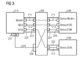
- FIG. 3 shows a schematic sketch of a second embodiment of the further arrangement according to the invention with a second embodiment of the connection unit according to the invention, in which the connection unit is simultaneously formed as a connection device.
- connection unit 220 combines the functionality of the connection device 20 of the embodiment of FIG. 1 and the connection unit 120 of the embodiment of FIG. 2 , This is obviously a particularly preferred embodiment of the further arrangement according to the invention and the connection unit according to the invention, since this allows a very flexible transmission of data between the electrical device 210 and the control devices 230 and 240.
- This relates on the one hand to the connection of the two control devices 230 and 240 to the one electrical device 210, whereby different logical devices 211, 212, 213 of the electrical device 210 are provided on the control device 230 and the second control device 240, respectively.
- connection unit 220 allows a COM / RS232 interface of a second type connector 215 of the electrical device 210 to be provided as an additional logical device 216 to the controller 230.
- the connection unit 220 has a first or control-device-side interface first Type 221, a second interface 222, a third or device-side interface of the first type 223, a device-side interface of the second type 224 and a connection of the second type 226.
- connection unit 220 can be used in a very wide variety of ways, thus opening up further application possibilities for the electrical device 210 and the control devices 230 and 240.
- FIG. 3 illustrated embodiments of the inventive arrangement or the connecting unit according to the invention by within the context of the present invention very particularly preferred embodiments.
Landscapes
- Engineering & Computer Science (AREA)
- Physics & Mathematics (AREA)
- General Engineering & Computer Science (AREA)
- Theoretical Computer Science (AREA)
- Mathematical Physics (AREA)
- Computer Hardware Design (AREA)
- General Physics & Mathematics (AREA)
- Information Transfer Systems (AREA)
- Selective Calling Equipment (AREA)
Applications Claiming Priority (1)
| Application Number | Priority Date | Filing Date | Title |
|---|---|---|---|
| DE102006059109A DE102006059109A1 (de) | 2006-12-08 | 2006-12-08 | Anordnungen, Verfahren und Vorrichtungen zur Übertragung von Daten zwischen einer Steuer-Einrichtung und einem elektrischen Gerät |
Publications (3)
| Publication Number | Publication Date |
|---|---|
| EP1944698A2 true EP1944698A2 (fr) | 2008-07-16 |
| EP1944698A3 EP1944698A3 (fr) | 2008-10-22 |
| EP1944698B1 EP1944698B1 (fr) | 2012-04-04 |
Family
ID=39272524
Family Applications (1)
| Application Number | Title | Priority Date | Filing Date |
|---|---|---|---|
| EP07117526A Not-in-force EP1944698B1 (fr) | 2006-12-08 | 2007-09-28 | Agencements, procédés et dispositifs de transmission de données entre un dispositif de commande et un appareil électrique |
Country Status (3)
| Country | Link |
|---|---|
| EP (1) | EP1944698B1 (fr) |
| AT (1) | ATE552558T1 (fr) |
| DE (1) | DE102006059109A1 (fr) |
Cited By (1)
| Publication number | Priority date | Publication date | Assignee | Title |
|---|---|---|---|---|
| CN115842869A (zh) * | 2022-11-23 | 2023-03-24 | 浙江省通信产业服务有限公司 | 一种基于物联网的数字乡村管理方法、装置及控制系统 |
Families Citing this family (1)
| Publication number | Priority date | Publication date | Assignee | Title |
|---|---|---|---|---|
| US8301822B2 (en) | 2009-09-23 | 2012-10-30 | Sandisk Il Ltd. | Multi-protocol storage device bridge |
Family Cites Families (6)
| Publication number | Priority date | Publication date | Assignee | Title |
|---|---|---|---|---|
| DE19631050A1 (de) * | 1996-08-01 | 1998-02-05 | Frank Bergler | Schnittstellenkonverter für USB |
| US6308239B1 (en) * | 1996-11-07 | 2001-10-23 | Hitachi, Ltd. | Interface switching apparatus and switching control method |
| US6282469B1 (en) * | 1998-07-22 | 2001-08-28 | Snap-On Technologies, Inc. | Computerized automotive service equipment using multipoint serial link data transmission protocols |
| US20010047441A1 (en) * | 2000-02-23 | 2001-11-29 | Mark Robertson | Communications system conduit for transferring data |
| US20030167345A1 (en) * | 2002-02-25 | 2003-09-04 | Knight Alexander N. | Communications bridge between a vehicle information network and a remote system |
| DE20214585U1 (de) * | 2002-09-20 | 2002-11-21 | W-Link Systems Inc., Hsinchu | Hub mit Funktion für die drahtlose Kommunikation |
-
2006
- 2006-12-08 DE DE102006059109A patent/DE102006059109A1/de not_active Ceased
-
2007
- 2007-09-28 EP EP07117526A patent/EP1944698B1/fr not_active Not-in-force
- 2007-09-28 AT AT07117526T patent/ATE552558T1/de active
Cited By (1)
| Publication number | Priority date | Publication date | Assignee | Title |
|---|---|---|---|---|
| CN115842869A (zh) * | 2022-11-23 | 2023-03-24 | 浙江省通信产业服务有限公司 | 一种基于物联网的数字乡村管理方法、装置及控制系统 |
Also Published As
| Publication number | Publication date |
|---|---|
| ATE552558T1 (de) | 2012-04-15 |
| EP1944698A3 (fr) | 2008-10-22 |
| DE102006059109A1 (de) | 2008-06-12 |
| EP1944698B1 (fr) | 2012-04-04 |
Similar Documents
| Publication | Publication Date | Title |
|---|---|---|
| EP2294764B1 (fr) | Module de communication et procédé pour connecter un appareil électrique à un réseau | |
| DE10211939A1 (de) | Kopplungsvorrichtung zum Ankoppeln von Geräten an ein Bussystem | |
| DE60305998T2 (de) | Einrichtung, Gateway und Verfahren zum Laden von Information zwischen on-board Ausrüstungen eines Flugzeugs und off-board Ladeeinrichtung | |
| DE102009030952A1 (de) | Drahtloses Kommunikationsgerät und Paketübertragungsverfahren dafür | |
| EP1944698B1 (fr) | Agencements, procédés et dispositifs de transmission de données entre un dispositif de commande et un appareil électrique | |
| DE102007025989A1 (de) | Verfahren zur Datenübertragung | |
| EP3439245B1 (fr) | Procédés de communication de données entre un capteur de position angulaire et une unité de contrôl d'un moteur ou de traitement | |
| DE19960565B4 (de) | Verfahren und Vorrichtung für entfernbare Peripheriebenutzerschnittstellenbedienfelder | |
| DE102011004358B3 (de) | Verfahren zum Übertragen von Daten über einen synchronen seriellen Datenbus | |
| DE102018129906A1 (de) | Kontrollsystem und Kontrollverfahren für einen Cursor | |
| EP2950199B1 (fr) | Procédé d'impression, système de réalisation du procédé d'impression, programme informatique correspondant et support de stockage correspondant lisible sur ordinateur | |
| WO2019161820A1 (fr) | Unité de communication intégrée | |
| EP4300898B1 (fr) | Machine à vide | |
| DE69222635T2 (de) | Anordnung zum treiben von differentiellen und unsymmetrischen rechnerbussen | |
| DE202019106455U1 (de) | IIoT(Industrial Internet of Things)-spezifisches Datenaustauschsystem | |
| DE202012103032U1 (de) | KVM - Schalter (Mehrfach - Computer - Schalter) mit integrierter Parallelübertragung, serieller peripherer Schnittstelle (SPI) und universellem seriellem Bus (USB) | |
| DE202011003748U1 (de) | Schraubsystem | |
| DE102018211702A1 (de) | Steuereinheit für ein Fahrassistenzsystem eines Kraftfahrzeugs | |
| DE29716311U1 (de) | Wartungsanordnung an einer Druckmaschine | |
| DE102018118510B4 (de) | Laborgerät, Laborgerätesystem und Verfahren zur Datenübertragung | |
| DE10314548B4 (de) | Verfahren, Computer und Computerprogrammmodule zur Übertragung von Daten in einem Computernetzwerk | |
| DE69227028T2 (de) | Verbindungsgerät und seine Verwendung in einer Verbindungsanordnung | |
| EP4331941A1 (fr) | Dispositif adaptateur et système de télécommunication | |
| DE102022115689A1 (de) | Adaptermodul zum Informationsaustausch zwischen zumindest zwei Teilnehmern eines Kommunikationsnetzwerkes und zugehöriges Verfahren, Teilnehmereinheiten eines Kommunikationsnetzwerkes mit einem solchen Adaptermodul, Bereitstellungseinheit, Kommunikationsnetzwerk mit einem solchen Adaptermodul sowie Signalfolge | |
| EP1617617A1 (fr) | Procédé et système à fournir des licences d'accès pour un dispositif d'automatisation |
Legal Events
| Date | Code | Title | Description |
|---|---|---|---|
| PUAI | Public reference made under article 153(3) epc to a published international application that has entered the european phase |
Free format text: ORIGINAL CODE: 0009012 |
|
| AK | Designated contracting states |
Kind code of ref document: A2 Designated state(s): AT BE BG CH CY CZ DE DK EE ES FI FR GB GR HU IE IS IT LI LT LU LV MC MT NL PL PT RO SE SI SK TR |
|
| AX | Request for extension of the european patent |
Extension state: AL BA HR MK RS |
|
| PUAL | Search report despatched |
Free format text: ORIGINAL CODE: 0009013 |
|
| AK | Designated contracting states |
Kind code of ref document: A3 Designated state(s): AT BE BG CH CY CZ DE DK EE ES FI FR GB GR HU IE IS IT LI LT LU LV MC MT NL PL PT RO SE SI SK TR |
|
| AX | Request for extension of the european patent |
Extension state: AL BA HR MK RS |
|
| RAP1 | Party data changed (applicant data changed or rights of an application transferred) |
Owner name: CINTERION WIRELESS MODULES GMBH |
|
| 17P | Request for examination filed |
Effective date: 20090422 |
|
| AKX | Designation fees paid |
Designated state(s): AT BE BG CH CY CZ DE DK EE ES FI FR GB GR HU IE IS IT LI LT LU LV MC MT NL PL PT RO SE SI SK TR |
|
| 17Q | First examination report despatched |
Effective date: 20090622 |
|
| 111Z | Information provided on other rights and legal means of execution |
Free format text: AT BE BG CH CY CZ DE DK EE ES FI FR GB GR HU IE IS IT LT LU LV MC MT NL PL PT RO SE SI SK TR Effective date: 20100218 |
|
| GRAP | Despatch of communication of intention to grant a patent |
Free format text: ORIGINAL CODE: EPIDOSNIGR1 |
|
| GRAS | Grant fee paid |
Free format text: ORIGINAL CODE: EPIDOSNIGR3 |
|
| GRAA | (expected) grant |
Free format text: ORIGINAL CODE: 0009210 |
|
| AK | Designated contracting states |
Kind code of ref document: B1 Designated state(s): AT BE BG CH CY CZ DE DK EE ES FI FR GB GR HU IE IS IT LI LT LU LV MC MT NL PL PT RO SE SI SK TR |
|
| REG | Reference to a national code |
Ref country code: GB Ref legal event code: FG4D Free format text: NOT ENGLISH |
|
| REG | Reference to a national code |
Ref country code: CH Ref legal event code: EP |
|
| REG | Reference to a national code |
Ref country code: AT Ref legal event code: REF Ref document number: 552558 Country of ref document: AT Kind code of ref document: T Effective date: 20120415 |
|
| REG | Reference to a national code |
Ref country code: IE Ref legal event code: FG4D Free format text: LANGUAGE OF EP DOCUMENT: GERMAN |
|
| REG | Reference to a national code |
Ref country code: DE Ref legal event code: R096 Ref document number: 502007009604 Country of ref document: DE Effective date: 20120531 |
|
| REG | Reference to a national code |
Ref country code: NL Ref legal event code: VDEP Effective date: 20120404 |
|
| LTIE | Lt: invalidation of european patent or patent extension |
Effective date: 20120404 |
|
| PG25 | Lapsed in a contracting state [announced via postgrant information from national office to epo] |
Ref country code: SE Free format text: LAPSE BECAUSE OF FAILURE TO SUBMIT A TRANSLATION OF THE DESCRIPTION OR TO PAY THE FEE WITHIN THE PRESCRIBED TIME-LIMIT Effective date: 20120404 Ref country code: PL Free format text: LAPSE BECAUSE OF FAILURE TO SUBMIT A TRANSLATION OF THE DESCRIPTION OR TO PAY THE FEE WITHIN THE PRESCRIBED TIME-LIMIT Effective date: 20120404 Ref country code: LT Free format text: LAPSE BECAUSE OF FAILURE TO SUBMIT A TRANSLATION OF THE DESCRIPTION OR TO PAY THE FEE WITHIN THE PRESCRIBED TIME-LIMIT Effective date: 20120404 Ref country code: IS Free format text: LAPSE BECAUSE OF FAILURE TO SUBMIT A TRANSLATION OF THE DESCRIPTION OR TO PAY THE FEE WITHIN THE PRESCRIBED TIME-LIMIT Effective date: 20120804 Ref country code: FI Free format text: LAPSE BECAUSE OF FAILURE TO SUBMIT A TRANSLATION OF THE DESCRIPTION OR TO PAY THE FEE WITHIN THE PRESCRIBED TIME-LIMIT Effective date: 20120404 Ref country code: SI Free format text: LAPSE BECAUSE OF FAILURE TO SUBMIT A TRANSLATION OF THE DESCRIPTION OR TO PAY THE FEE WITHIN THE PRESCRIBED TIME-LIMIT Effective date: 20120404 Ref country code: CY Free format text: LAPSE BECAUSE OF FAILURE TO SUBMIT A TRANSLATION OF THE DESCRIPTION OR TO PAY THE FEE WITHIN THE PRESCRIBED TIME-LIMIT Effective date: 20120404 |
|
| PG25 | Lapsed in a contracting state [announced via postgrant information from national office to epo] |
Ref country code: GR Free format text: LAPSE BECAUSE OF FAILURE TO SUBMIT A TRANSLATION OF THE DESCRIPTION OR TO PAY THE FEE WITHIN THE PRESCRIBED TIME-LIMIT Effective date: 20120705 Ref country code: LV Free format text: LAPSE BECAUSE OF FAILURE TO SUBMIT A TRANSLATION OF THE DESCRIPTION OR TO PAY THE FEE WITHIN THE PRESCRIBED TIME-LIMIT Effective date: 20120404 Ref country code: PT Free format text: LAPSE BECAUSE OF FAILURE TO SUBMIT A TRANSLATION OF THE DESCRIPTION OR TO PAY THE FEE WITHIN THE PRESCRIBED TIME-LIMIT Effective date: 20120806 |
|
| PG25 | Lapsed in a contracting state [announced via postgrant information from national office to epo] |
Ref country code: CZ Free format text: LAPSE BECAUSE OF FAILURE TO SUBMIT A TRANSLATION OF THE DESCRIPTION OR TO PAY THE FEE WITHIN THE PRESCRIBED TIME-LIMIT Effective date: 20120404 Ref country code: SK Free format text: LAPSE BECAUSE OF FAILURE TO SUBMIT A TRANSLATION OF THE DESCRIPTION OR TO PAY THE FEE WITHIN THE PRESCRIBED TIME-LIMIT Effective date: 20120404 Ref country code: DK Free format text: LAPSE BECAUSE OF FAILURE TO SUBMIT A TRANSLATION OF THE DESCRIPTION OR TO PAY THE FEE WITHIN THE PRESCRIBED TIME-LIMIT Effective date: 20120404 Ref country code: EE Free format text: LAPSE BECAUSE OF FAILURE TO SUBMIT A TRANSLATION OF THE DESCRIPTION OR TO PAY THE FEE WITHIN THE PRESCRIBED TIME-LIMIT Effective date: 20120404 Ref country code: RO Free format text: LAPSE BECAUSE OF FAILURE TO SUBMIT A TRANSLATION OF THE DESCRIPTION OR TO PAY THE FEE WITHIN THE PRESCRIBED TIME-LIMIT Effective date: 20120404 Ref country code: NL Free format text: LAPSE BECAUSE OF FAILURE TO SUBMIT A TRANSLATION OF THE DESCRIPTION OR TO PAY THE FEE WITHIN THE PRESCRIBED TIME-LIMIT Effective date: 20120404 |
|
| PLBE | No opposition filed within time limit |
Free format text: ORIGINAL CODE: 0009261 |
|
| STAA | Information on the status of an ep patent application or granted ep patent |
Free format text: STATUS: NO OPPOSITION FILED WITHIN TIME LIMIT |
|
| PG25 | Lapsed in a contracting state [announced via postgrant information from national office to epo] |
Ref country code: IT Free format text: LAPSE BECAUSE OF FAILURE TO SUBMIT A TRANSLATION OF THE DESCRIPTION OR TO PAY THE FEE WITHIN THE PRESCRIBED TIME-LIMIT Effective date: 20120404 |
|
| 26N | No opposition filed |
Effective date: 20130107 |
|
| BERE | Be: lapsed |
Owner name: CINTERION WIRELESS MODULES G.M.B.H. Effective date: 20120930 |
|
| PG25 | Lapsed in a contracting state [announced via postgrant information from national office to epo] |
Ref country code: ES Free format text: LAPSE BECAUSE OF FAILURE TO SUBMIT A TRANSLATION OF THE DESCRIPTION OR TO PAY THE FEE WITHIN THE PRESCRIBED TIME-LIMIT Effective date: 20120715 Ref country code: MC Free format text: LAPSE BECAUSE OF NON-PAYMENT OF DUE FEES Effective date: 20120930 |
|
| REG | Reference to a national code |
Ref country code: CH Ref legal event code: PL |
|
| REG | Reference to a national code |
Ref country code: DE Ref legal event code: R097 Ref document number: 502007009604 Country of ref document: DE Effective date: 20130107 |
|
| REG | Reference to a national code |
Ref country code: DE Ref legal event code: R082 Ref document number: 502007009604 Country of ref document: DE Representative=s name: EISENFUEHR, SPEISER & PARTNER, DE |
|
| REG | Reference to a national code |
Ref country code: IE Ref legal event code: MM4A |
|
| REG | Reference to a national code |
Ref country code: DE Ref legal event code: R081 Ref document number: 502007009604 Country of ref document: DE Owner name: GEMALTO M2M GMBH, DE Free format text: FORMER OWNER: CINTERION WIRELESS MODULES GMBH, 81669 MUENCHEN, DE Effective date: 20130522 Ref country code: DE Ref legal event code: R082 Ref document number: 502007009604 Country of ref document: DE Representative=s name: EISENFUEHR, SPEISER & PARTNER, DE Effective date: 20130522 Ref country code: DE Ref legal event code: R082 Ref document number: 502007009604 Country of ref document: DE Representative=s name: GREVIN, EMMANUEL, FR Effective date: 20130522 |
|
| PG25 | Lapsed in a contracting state [announced via postgrant information from national office to epo] |
Ref country code: BG Free format text: LAPSE BECAUSE OF FAILURE TO SUBMIT A TRANSLATION OF THE DESCRIPTION OR TO PAY THE FEE WITHIN THE PRESCRIBED TIME-LIMIT Effective date: 20120704 Ref country code: LI Free format text: LAPSE BECAUSE OF NON-PAYMENT OF DUE FEES Effective date: 20120930 Ref country code: CH Free format text: LAPSE BECAUSE OF NON-PAYMENT OF DUE FEES Effective date: 20120930 Ref country code: IE Free format text: LAPSE BECAUSE OF NON-PAYMENT OF DUE FEES Effective date: 20120928 Ref country code: BE Free format text: LAPSE BECAUSE OF NON-PAYMENT OF DUE FEES Effective date: 20120930 |
|
| REG | Reference to a national code |
Ref country code: AT Ref legal event code: MM01 Ref document number: 552558 Country of ref document: AT Kind code of ref document: T Effective date: 20120928 |
|
| PG25 | Lapsed in a contracting state [announced via postgrant information from national office to epo] |
Ref country code: MT Free format text: LAPSE BECAUSE OF FAILURE TO SUBMIT A TRANSLATION OF THE DESCRIPTION OR TO PAY THE FEE WITHIN THE PRESCRIBED TIME-LIMIT Effective date: 20120404 |
|
| REG | Reference to a national code |
Ref country code: DE Ref legal event code: R082 Ref document number: 502007009604 Country of ref document: DE Representative=s name: GREVIN, EMMANUEL, FR |
|
| PG25 | Lapsed in a contracting state [announced via postgrant information from national office to epo] |
Ref country code: AT Free format text: LAPSE BECAUSE OF NON-PAYMENT OF DUE FEES Effective date: 20120928 |
|
| PG25 | Lapsed in a contracting state [announced via postgrant information from national office to epo] |
Ref country code: TR Free format text: LAPSE BECAUSE OF FAILURE TO SUBMIT A TRANSLATION OF THE DESCRIPTION OR TO PAY THE FEE WITHIN THE PRESCRIBED TIME-LIMIT Effective date: 20120404 |
|
| PG25 | Lapsed in a contracting state [announced via postgrant information from national office to epo] |
Ref country code: LU Free format text: LAPSE BECAUSE OF NON-PAYMENT OF DUE FEES Effective date: 20120928 |
|
| PG25 | Lapsed in a contracting state [announced via postgrant information from national office to epo] |
Ref country code: HU Free format text: LAPSE BECAUSE OF FAILURE TO SUBMIT A TRANSLATION OF THE DESCRIPTION OR TO PAY THE FEE WITHIN THE PRESCRIBED TIME-LIMIT Effective date: 20070928 |
|
| REG | Reference to a national code |
Ref country code: FR Ref legal event code: PLFP Year of fee payment: 10 |
|
| PGFP | Annual fee paid to national office [announced via postgrant information from national office to epo] |
Ref country code: GB Payment date: 20160825 Year of fee payment: 10 Ref country code: DE Payment date: 20160823 Year of fee payment: 10 |
|
| PGFP | Annual fee paid to national office [announced via postgrant information from national office to epo] |
Ref country code: FR Payment date: 20160822 Year of fee payment: 10 |
|
| REG | Reference to a national code |
Ref country code: DE Ref legal event code: R119 Ref document number: 502007009604 Country of ref document: DE |
|
| GBPC | Gb: european patent ceased through non-payment of renewal fee |
Effective date: 20170928 |
|
| REG | Reference to a national code |
Ref country code: FR Ref legal event code: ST Effective date: 20180531 |
|
| PG25 | Lapsed in a contracting state [announced via postgrant information from national office to epo] |
Ref country code: GB Free format text: LAPSE BECAUSE OF NON-PAYMENT OF DUE FEES Effective date: 20170928 Ref country code: DE Free format text: LAPSE BECAUSE OF NON-PAYMENT OF DUE FEES Effective date: 20180404 |
|
| PG25 | Lapsed in a contracting state [announced via postgrant information from national office to epo] |
Ref country code: FR Free format text: LAPSE BECAUSE OF NON-PAYMENT OF DUE FEES Effective date: 20171002 |