EP1944859A2 - Vorrichtung und Verfahren zum Antreiben eines BLDC-Motors und zur Erhöhung der Antriebsgeschwindigkeit einer BLDC-Motors - Google Patents
Vorrichtung und Verfahren zum Antreiben eines BLDC-Motors und zur Erhöhung der Antriebsgeschwindigkeit einer BLDC-Motors Download PDFInfo
- Publication number
- EP1944859A2 EP1944859A2 EP07117144A EP07117144A EP1944859A2 EP 1944859 A2 EP1944859 A2 EP 1944859A2 EP 07117144 A EP07117144 A EP 07117144A EP 07117144 A EP07117144 A EP 07117144A EP 1944859 A2 EP1944859 A2 EP 1944859A2
- Authority
- EP
- European Patent Office
- Prior art keywords
- voltage
- bldc motor
- driving speed
- time point
- rectifier
- Prior art date
- Legal status (The legal status is an assumption and is not a legal conclusion. Google has not performed a legal analysis and makes no representation as to the accuracy of the status listed.)
- Withdrawn
Links
Images


Classifications
-
- A—HUMAN NECESSITIES
- A47—FURNITURE; DOMESTIC ARTICLES OR APPLIANCES; COFFEE MILLS; SPICE MILLS; SUCTION CLEANERS IN GENERAL
- A47J—KITCHEN EQUIPMENT; COFFEE MILLS; SPICE MILLS; APPARATUS FOR MAKING BEVERAGES
- A47J45/00—Devices for fastening or gripping kitchen utensils or crockery
- A47J45/06—Handles for hollow-ware articles
- A47J45/062—Bowl handles
-
- H—ELECTRICITY
- H02—GENERATION; CONVERSION OR DISTRIBUTION OF ELECTRIC POWER
- H02P—CONTROL OR REGULATION OF ELECTRIC MOTORS, ELECTRIC GENERATORS OR DYNAMO-ELECTRIC CONVERTERS; CONTROLLING TRANSFORMERS, REACTORS OR CHOKE COILS
- H02P6/00—Arrangements for controlling synchronous motors or other dynamo-electric motors using electronic commutation dependent on the rotor position; Electronic commutators therefor
- H02P6/14—Electronic commutators
-
- A—HUMAN NECESSITIES
- A47—FURNITURE; DOMESTIC ARTICLES OR APPLIANCES; COFFEE MILLS; SPICE MILLS; SUCTION CLEANERS IN GENERAL
- A47J—KITCHEN EQUIPMENT; COFFEE MILLS; SPICE MILLS; APPARATUS FOR MAKING BEVERAGES
- A47J45/00—Devices for fastening or gripping kitchen utensils or crockery
- A47J45/06—Handles for hollow-ware articles
- A47J45/061—Saucepan, frying-pan handles
-
- H—ELECTRICITY
- H02—GENERATION; CONVERSION OR DISTRIBUTION OF ELECTRIC POWER
- H02P—CONTROL OR REGULATION OF ELECTRIC MOTORS, ELECTRIC GENERATORS OR DYNAMO-ELECTRIC CONVERTERS; CONTROLLING TRANSFORMERS, REACTORS OR CHOKE COILS
- H02P6/00—Arrangements for controlling synchronous motors or other dynamo-electric motors using electronic commutation dependent on the rotor position; Electronic commutators therefor
- H02P6/14—Electronic commutators
- H02P6/16—Circuit arrangements for detecting position
- H02P6/18—Circuit arrangements for detecting position without separate position detecting elements
- H02P6/182—Circuit arrangements for detecting position without separate position detecting elements using back-emf in windings
Definitions
- the present invention relates to a device and method of driving a brushless DC (BLDC) motor, and more particularly, to a device and method of driving a BLDC motor that can increase the maximum driving speed of the BLDC motor.
- BLDC brushless DC
- a BLDC motor indicates a DC motor which uses a semiconductor device instead of a brush.
- the BLDC motor detects the position of a rotor using a magnetic or optical sensor.
- the BLDC motor may detect the position of the rotor using a sensorless method.
- the sensorless BLDC motor is disclosed in Korean Unexamined Patent Publication No. 1999-81167 , in which the position of a rotor is detected by a sensorless detector and the controller of a driving device.
- a plurality of comparators compare voltages of phases of the BLDC motor with a reference voltage, as shown in FIG. 3 .
- an output signal of each comparator is changed at a time point when a terminal voltage of an unexcited phase of the BLDC motor is 1/2 of an output voltage of a rectifier (zero-cross time point of FIG. 3 ).
- the controller detects the position of the rotor of the BLDC motor by detecting a variation in the output signal of the comparator.
- the controller of the driving device allows the driving speed of the BLDC motor to exceed the rated speed by advancing a phase switching time point, which is a time point when a power switch of an inverter is turned on/off when the motor is driven at the rated speed. This is referred to as "weak flux control".
- the phase switching time point cannot be earlier than the zero-cross time point shown in FIG. 3 . Accordingly, the weak flux control range is restricted, and thus the speed of the BLDC motor cannot significantly increase.
- a device to drive a brushless DC (BLDC) motor including: a rectifier which converts an AC voltage into a DC voltage; an inverter which converts the DC voltage into an AC voltage by switching a plurality of power switches and supplies the converted AC voltage to the BLDC motor; and a microcomputer which detects a position of a rotor before a terminal voltage of the BLDC motor exceeds 1/2 of an output voltage of the rectifier and performs phase switching, when a driving speed of the BLDC motor reaches a rated speed.
- BLDC brushless DC
- the BLDC motor may be driven using a two-excitation sensorless driving method and the terminal voltage may be a terminal voltage of an unexcited phase of the three phases of the BLDC motor.
- the microcomputer may include a position detecting unit which detects the position of the rotor of the BLDC motor, and the position detecting unit may detect the position of the rotor by detecting any time point of a period when the terminal voltage of unexcited phase is in a range from 0 to 1/2 of the output voltage of the rectifier.
- the microcomputer may detect the position of the rotor by detecting a time point when the terminal voltage of the unexcited phase is 1/2 of the output voltage of the rectifier and perform the phase switching, when the driving speed of the BLDC motor is less than the rated speed.
- the time point when the terminal voltage of the unexcited phase is 1/2 of the output voltage of the rectifier is a time point when a pole of a permanent magnet mounted in the rotor passes through the unexcited phase.
- a device to drive a brushless DC (BLDC) motor including: a rectifier which converts an AC voltage into a DC voltage; an inverter which converts the DC voltage into an AC voltage and supplies the AC voltage to the BLDC motor; and a microcomputer having a position detecting unit detecting a position of a rotor of the BLDC motor by detecting a time point when a terminal voltage is 1/2 of an output voltage of the rectifier when the driving speed of the BLDC motor is less than a rated speed, and by detecting any time point of a period when the terminal voltage is in a range from 0 to 1/2 of the output voltage of the rectifier when the driving speed of the BLDC motor is greater than or equal to the rated speed.
- a position detecting unit detecting a position of a rotor of the BLDC motor by detecting a time point when a terminal voltage is 1/2 of an output voltage of the rectifier when the driving speed of the BLDC motor is less than a rated speed, and by detecting any
- the microcomputer may advance a position detection time point of the rotor and a phase switching time point to increase the weak flux control range when the driving speed of the BLDC motor is greater than or equal to the rated speed.
- a device to drive a brushless DC (BLDC) motor including: a rectifier which converts an AC voltage into a DC voltage; an inverter which converts the DC voltage into an AC voltage by switching a plurality of power switches and supplies the converted AC voltage to the BLDC motor; and a microcomputer which detects a position of a rotor and performs phase switching before a terminal voltage of the BLDC motor exceeds 1/2 of an output voltage of the rectifier when the BLDC motor is driven.
- BLDC brushless DC
- BLDC brushless DC
- the method may further include detecting the position of the rotor by detecting a time point when the terminal voltage is 1/2 of the output voltage of the rectifier and performing the phase switching, when the driving speed is less than the rated speed.
- the method may further include determining whether the driving speed has reached a desired driving speed, and when it is determined that the driving speed has reached the desired driving speed, determining whether the driving speed is continuously increasing, and when it is determined that the driving speed has not reached the desired driving speed, driving the BLDC motor while maintaining the applied voltages of phases of the motor, a position detection time point of the rotor and a phase switching time point.
- the driving speed is determined to be continuously increasing, it is determined that the driving speed has not reached the rated speed, and when the driving speed is determined to not be continuously increasing, it is determined that the driving speed has reached the rated speed.
- the device to drive the BLDC motor includes a rectifier 12 that converts an AC voltage of an external AC power supply source 16 into a DC voltage, an inverter 11 which converts the DC voltage outputted from the rectifier 12 into an AC voltage by switching a plurality of power switches and which transmits the AC voltage to each phase of the BLDC motor 10, a smoothing capacitor 13, a division resistor 14, a filter 15 to amplify a voltage detected by the division resistor 14, and a microcomputer 20.
- the microcomputer 20 includes an A/D converting port 22 which receives the terminal voltages (that is, the voltages of phases) of the BLDC motor 10 and the output voltage of the rectifier 12 and performs A/D conversion, and a position detecting unit 21 which compares the terminal voltages and the output voltage of the rectifier 12 and detects the position of a rotor of the BLDC motor.
- the position detecting unit 21 has a comparison equation to perform the same function as the comparators of a conventional sensorless detector. When a reference voltage compared with each terminal voltage is changed and substituted for the comparison equation, it is possible to detect the position of the rotor at a desired time point.
- the microcomputer 20 controls the switching of the power switches of the inverter 11 and detects driving current of the BLDC motor 10 using an input voltage of the filter 15.
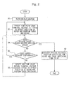
- the microcomputer 20 applies a voltage to the BLDC motor 10 to turn on the BLDC motor 10 and increases the applied voltage, using PWM control, to increase the driving speed of the BLDC motor 10 (operation 30).
- the position detecting unit 21 detects a time point when the voltage of the unexcited phase, among the terminal voltages inputted to the A/D converting port is 1/2 of the output voltage of the rectifier to detect the position of the rotor (operation 32).
- This time point is a point B shown in FIG. 3
- the three trapezoidal waveforms shown in FIG. 3 indicate applied voltages or counter-electromotive voltages of the phases of the BLDC motor 10.
- a rectangular waveform included in each trapezoidal waveform indicates current applied to each phase of the BLDC motor 10.
- the time point when the terminal voltage of the unexcited phase is 1/2Vdc is a time point when a pole of a permanent magnet mounted in the rotor passes through the unexcited phase.
- the microcomputer 20 When the position of the rotor is detected, the microcomputer 20 performs phase switching, which is illustrated by point C shown in FIG. 3 .
- the phase switching indicates an operation to turn on/off the power switches of the inverter 11 in order to allow the phases to be excited or unexcited.
- a period from the position detection time point of the rotor to the phase switching time point is called a phase switching phase.
- the phase switching phase of operation 32 is, for example, 30°, which is the phase difference between the point B and the point C.
- the driving speed of the BLDC motor 10 is detected. It is determined whether the driving speed of the BLDC motor 10 reaches a desired driving speed (operation 34).
- the desired driving speed indicates the driving speed of the BLDC motor 10 which is instructed by the main microcomputer.
- the microcomputer 20 continuously drives the BLDC 10 while the applied voltages of the BLDC motor, the position detection time point of the rotor and the phase switching time point are maintained (operation 40). However, if the driving speed of the BLDC motor 10 does not reach the desired driving speed, it is determined whether the driving speed of the BLDC motor 10 is continuously increasing (operation 36).
- the method returns to operation 32 because it is determined that the driving speed of the BLDC motor 10 has not reached a rated speed. In contrast, if the driving speed of the BLDC motor 10 no longer increases, the microcomputer 20 determines that the driving speed of the BLDC motor 10 reached the rated speed and performs operation 38.
- the driving speed of the BLDC motor 10 gradually increases.
- the voltage applied to each phase become equal to the counter-electromotive voltage and thus the driving speed no longer increases. Accordingly, if the driving speed of the BLDC 10 no longer increases despite the increasing of the applied voltages, it is determined that the BLDC motor 10 has reached the rated speed.
- the position detecting unit 21 detects any time point (0 ⁇ the terminal voltage of the unexcited phase ⁇ 1/2Vdc) before the time point when the terminal voltage of the unexcited phase among the terminal voltages inputted to the A/D converting port 22 is 1/2 of the output voltage of the rectifier to detect the position of the rotor. That is, the position detection time point of the rotor can be selected in a range of 0 ⁇ the voltage terminal of the unexcited phase ⁇ 1/2Vdc, if necessary (for example, point A shown in FIG. 3 ). The time point before the terminal voltage of the unexcited phase becomes 1/2Vdc indicates a time point before the pole of the permanent magnet mounted in the rotor passes through the unexcited phase.
- the microcomputer 20 When the position of the rotor is detected, the microcomputer 20 performs the phase switching (operation 38). If the microcomputer 20 detects the position of the rotor at a time point when the terminal voltage of the unexcited phase is 0 (e.g., point A shown in FIG. 3 ) and the phase switching is performed at point C shown in FIG. 3 , the phase switching phase being 60°.
- the phase switching phase may be adjusted, if necessary. In particular, when the phase switching phase is reduced, the phase switching time point is advanced and the direction of the magnetic field generated in the excited phase is changed to offset the magnetic field of the permanent magnet of the rotor to cause the counter-electromotive voltage. Accordingly, the counter-electromotive voltage of the BLDC motor 10 is reduced, and thus the driving speed of the BLDC motor 10 increases.
- the phase switching phase When the phase switching phase is reduced to 0°, the position of the rotor is detected, and the phase switching is performed at point A. Thus, the counter-electromotive voltage of the BLDC motor 10 significantly decreases. Accordingly, it is possible to increase the adjustment range of the phase switching phase up to twice that of the conventional device which cannot allow the phase switching time point to become earlier than the point B. Thus, the decreased width of the counter-electromotive voltage is higher than that of the conventional device and thus the driving speed of the BLDC motor 10 significantly increases.
- the phase switching time point becomes earlier than that of the conventional device. Accordingly, the weak flux control range of the BLDC motor 10 increases.
- the method returns to operation 34. If the driving speed of the BLDC motor 10 reaches the desired driving speed, the BLDC motor 10 is driven while maintaining the applied voltages of the phases, the position detection time point of the rotor and the phase switching time point (operation 40). However, if the driving speed of the BLDC motor 10 does not reach the desired driving speed, operations 36 and 38 are performed again.
- the position of the rotor can be detected in the range of 0 ⁇ the terminal voltage of the unexcited phase ⁇ 1/2Vdc, even when the driving speed of the BLDC motor 10 is less than the rated speed.
- the present embodiment it is possible to significantly increase a maximum driving speed of the BLDC motor by significantly decreasing the counter-electromotive voltage of the BLDC motor compared with the conventional device.
Landscapes
- Engineering & Computer Science (AREA)
- Power Engineering (AREA)
- Food Science & Technology (AREA)
- Control Of Motors That Do Not Use Commutators (AREA)
Applications Claiming Priority (1)
| Application Number | Priority Date | Filing Date | Title |
|---|---|---|---|
| KR1020070002627A KR20080065467A (ko) | 2007-01-09 | 2007-01-09 | 비엘디씨모터의 구동장치 및 구동방법 |
Publications (1)
| Publication Number | Publication Date |
|---|---|
| EP1944859A2 true EP1944859A2 (de) | 2008-07-16 |
Family
ID=39367623
Family Applications (1)
| Application Number | Title | Priority Date | Filing Date |
|---|---|---|---|
| EP07117144A Withdrawn EP1944859A2 (de) | 2007-01-09 | 2007-09-25 | Vorrichtung und Verfahren zum Antreiben eines BLDC-Motors und zur Erhöhung der Antriebsgeschwindigkeit einer BLDC-Motors |
Country Status (4)
| Country | Link |
|---|---|
| US (1) | US20080166109A1 (de) |
| EP (1) | EP1944859A2 (de) |
| KR (1) | KR20080065467A (de) |
| CN (1) | CN101222194A (de) |
Families Citing this family (4)
| Publication number | Priority date | Publication date | Assignee | Title |
|---|---|---|---|---|
| KR101288825B1 (ko) * | 2011-12-30 | 2013-07-23 | 노틸러스효성 주식회사 | Bldc모터의 이상 감지 시스템 및 이상 감지 방법 |
| CN102638212B (zh) * | 2012-04-24 | 2015-02-11 | 台州学院 | 无刷直流电机驱动器 |
| JP7468381B2 (ja) * | 2021-01-27 | 2024-04-16 | 株式会社デンソー | 演算装置及びモータ駆動装置 |
| CN119093803B (zh) * | 2024-11-08 | 2025-02-28 | 中国船舶集团有限公司第七〇七研究所 | 一种伺服系统电机换相零位自动标定方法、系统及装置 |
Family Cites Families (4)
| Publication number | Priority date | Publication date | Assignee | Title |
|---|---|---|---|---|
| US4511834A (en) * | 1982-12-23 | 1985-04-16 | Borg-Warner Corporation | Control and stabilizing system for damperless synchronous motor |
| US4743815A (en) * | 1987-09-01 | 1988-05-10 | Emerson Electric Co. | Brushless permanent magnet motor system |
| JP3297159B2 (ja) * | 1993-09-14 | 2002-07-02 | 東芝キヤリア株式会社 | 直流ブラシレスモータの駆動装置およびその良否識別方法 |
| TW328190B (en) * | 1994-06-14 | 1998-03-11 | Toshiba Co Ltd | Control device of brushless motor and method of fault detection and air conditioner |
-
2007
- 2007-01-09 KR KR1020070002627A patent/KR20080065467A/ko not_active Withdrawn
- 2007-09-18 US US11/902,052 patent/US20080166109A1/en not_active Abandoned
- 2007-09-25 EP EP07117144A patent/EP1944859A2/de not_active Withdrawn
- 2007-10-08 CN CNA2007101627320A patent/CN101222194A/zh active Pending
Also Published As
| Publication number | Publication date |
|---|---|
| US20080166109A1 (en) | 2008-07-10 |
| KR20080065467A (ko) | 2008-07-14 |
| CN101222194A (zh) | 2008-07-16 |
Similar Documents
| Publication | Publication Date | Title |
|---|---|---|
| US9998059B2 (en) | Motor driving apparatus | |
| US20100148710A1 (en) | Apparatus and method for controlling a bldc motor | |
| US7190131B2 (en) | Device and method for starting brushless direct current motor | |
| US20040130284A1 (en) | Apparatus and method for controlling brushless DC motor | |
| US6747435B2 (en) | Apparatus for controlling an operation of motor and control method thereof | |
| EP3651348B1 (de) | Motorantriebsvorrichtung | |
| KR102619910B1 (ko) | 상전압 검출을 이용한 브러시리스 직류모터 기동 제어방법 및 장치 | |
| US8829834B2 (en) | Motor driving control apparatus and method, and motor using the same | |
| EP1944859A2 (de) | Vorrichtung und Verfahren zum Antreiben eines BLDC-Motors und zur Erhöhung der Antriebsgeschwindigkeit einer BLDC-Motors | |
| US7235941B2 (en) | Phase commutation method of brushless direct current motor | |
| JP2006149097A (ja) | モータ制御装置 | |
| JP6935349B2 (ja) | モータ駆動装置 | |
| KR20180074213A (ko) | 전원보상을 이용한 브러시리스 직류모터 구동 방법 및 장치 | |
| KR101490185B1 (ko) | 센서리스 bldc 모터의 기동 장치 및 방법 | |
| US10873278B2 (en) | Motor driving system and motor operation recovering method | |
| JP6044854B2 (ja) | 電動工具 | |
| KR101699182B1 (ko) | 센서리스 모터 시분할 역기전력 검출 시스템 및 방법 | |
| JP2014158324A (ja) | モータの駆動制御装置及びモータの駆動制御装置の制御方法 | |
| EP3883120B1 (de) | Technologien zur adaptiven mehrpulskommutierung für bürstenlose gleichstrommotoren | |
| KR102509725B1 (ko) | 모터 구동 장치 | |
| KR20060077817A (ko) | 비엘디씨 모터의 구동장치 및 방법 | |
| KR101514663B1 (ko) | 센서리스 bldc 모터의 기동 장치 및 방법 | |
| JP2012019619A (ja) | モータ制御装置 | |
| KR20160092605A (ko) | Bldc 모터의 기동전류 저감 구동방법 | |
| JP2006180651A (ja) | モータ制御装置 |
Legal Events
| Date | Code | Title | Description |
|---|---|---|---|
| PUAI | Public reference made under article 153(3) epc to a published international application that has entered the european phase |
Free format text: ORIGINAL CODE: 0009012 |
|
| AK | Designated contracting states |
Kind code of ref document: A2 Designated state(s): AT BE BG CH CY CZ DE DK EE ES FI FR GB GR HU IE IS IT LI LT LU LV MC MT NL PL PT RO SE SI SK TR |
|
| AX | Request for extension of the european patent |
Extension state: AL BA HR MK RS |
|
| STAA | Information on the status of an ep patent application or granted ep patent |
Free format text: STATUS: THE APPLICATION IS DEEMED TO BE WITHDRAWN |
|
| 18D | Application deemed to be withdrawn |
Effective date: 20100401 |