EP1944875A2 - Vorrichtung und Verfahren zum Zuweisen von Ressourcen in einem Einzelträgerfrequenzteilungs-Mehrfachzugriffssystem - Google Patents
Vorrichtung und Verfahren zum Zuweisen von Ressourcen in einem Einzelträgerfrequenzteilungs-Mehrfachzugriffssystem Download PDFInfo
- Publication number
- EP1944875A2 EP1944875A2 EP08000316A EP08000316A EP1944875A2 EP 1944875 A2 EP1944875 A2 EP 1944875A2 EP 08000316 A EP08000316 A EP 08000316A EP 08000316 A EP08000316 A EP 08000316A EP 1944875 A2 EP1944875 A2 EP 1944875A2
- Authority
- EP
- European Patent Office
- Prior art keywords
- mirroring
- hopping
- cell
- resource unit
- inter
- Prior art date
- Legal status (The legal status is an assumption and is not a legal conclusion. Google has not performed a legal analysis and makes no representation as to the accuracy of the status listed.)
- Granted
Links
Images


Classifications
-
- H—ELECTRICITY
- H04—ELECTRIC COMMUNICATION TECHNIQUE
- H04W—WIRELESS COMMUNICATION NETWORKS
- H04W72/00—Local resource management
- H04W72/04—Wireless resource allocation
- H04W72/044—Wireless resource allocation based on the type of the allocated resource
- H04W72/0446—Resources in time domain, e.g. slots or frames
-
- H—ELECTRICITY
- H04—ELECTRIC COMMUNICATION TECHNIQUE
- H04B—TRANSMISSION
- H04B1/00—Details of transmission systems, not covered by a single one of groups H04B3/00 - H04B13/00; Details of transmission systems not characterised by the medium used for transmission
- H04B1/69—Spread spectrum techniques
- H04B1/713—Spread spectrum techniques using frequency hopping
- H04B1/7143—Arrangements for generation of hop patterns
-
- H—ELECTRICITY
- H04—ELECTRIC COMMUNICATION TECHNIQUE
- H04B—TRANSMISSION
- H04B1/00—Details of transmission systems, not covered by a single one of groups H04B3/00 - H04B13/00; Details of transmission systems not characterised by the medium used for transmission
- H04B1/69—Spread spectrum techniques
- H04B1/713—Spread spectrum techniques using frequency hopping
-
- H—ELECTRICITY
- H04—ELECTRIC COMMUNICATION TECHNIQUE
- H04L—TRANSMISSION OF DIGITAL INFORMATION, e.g. TELEGRAPHIC COMMUNICATION
- H04L5/00—Arrangements affording multiple use of the transmission path
- H04L5/02—Channels characterised by the type of signal
- H04L5/023—Multiplexing of multicarrier modulation signals, e.g. multi-user orthogonal frequency division multiple access [OFDMA]
-
- H—ELECTRICITY
- H04—ELECTRIC COMMUNICATION TECHNIQUE
- H04W—WIRELESS COMMUNICATION NETWORKS
- H04W72/00—Local resource management
- H04W72/04—Wireless resource allocation
- H04W72/044—Wireless resource allocation based on the type of the allocated resource
- H04W72/0453—Resources in frequency domain, e.g. a carrier in FDMA
-
- H—ELECTRICITY
- H04—ELECTRIC COMMUNICATION TECHNIQUE
- H04W—WIRELESS COMMUNICATION NETWORKS
- H04W72/00—Local resource management
- H04W72/04—Wireless resource allocation
- H04W72/044—Wireless resource allocation based on the type of the allocated resource
- H04W72/0466—Wireless resource allocation based on the type of the allocated resource the resource being a scrambling code
-
- H—ELECTRICITY
- H04—ELECTRIC COMMUNICATION TECHNIQUE
- H04W—WIRELESS COMMUNICATION NETWORKS
- H04W72/00—Local resource management
- H04W72/20—Control channels or signalling for resource management
-
- H—ELECTRICITY
- H04—ELECTRIC COMMUNICATION TECHNIQUE
- H04W—WIRELESS COMMUNICATION NETWORKS
- H04W72/00—Local resource management
- H04W72/20—Control channels or signalling for resource management
- H04W72/21—Control channels or signalling for resource management in the uplink direction of a wireless link, i.e. towards the network
-
- H—ELECTRICITY
- H04—ELECTRIC COMMUNICATION TECHNIQUE
- H04B—TRANSMISSION
- H04B1/00—Details of transmission systems, not covered by a single one of groups H04B3/00 - H04B13/00; Details of transmission systems not characterised by the medium used for transmission
- H04B1/69—Spread spectrum techniques
- H04B1/713—Spread spectrum techniques using frequency hopping
- H04B1/715—Interference-related aspects
- H04B2001/7154—Interference-related aspects with means for preventing interference
-
- H—ELECTRICITY
- H04—ELECTRIC COMMUNICATION TECHNIQUE
- H04J—MULTIPLEX COMMUNICATION
- H04J13/00—Code division multiplex systems
- H04J13/16—Code allocation
- H04J13/18—Allocation of orthogonal codes
-
- H—ELECTRICITY
- H04—ELECTRIC COMMUNICATION TECHNIQUE
- H04W—WIRELESS COMMUNICATION NETWORKS
- H04W88/00—Devices specially adapted for wireless communication networks, e.g. terminals, base stations or access point devices
- H04W88/02—Terminal devices
-
- H—ELECTRICITY
- H04—ELECTRIC COMMUNICATION TECHNIQUE
- H04W—WIRELESS COMMUNICATION NETWORKS
- H04W88/00—Devices specially adapted for wireless communication networks, e.g. terminals, base stations or access point devices
- H04W88/08—Access point devices
Definitions
- the present invention relates to a method and apparatus for efficiently allocating control channel transmission resources when a packet data channel and a control channel are transmitted in the same transmission period in a Single Carrier-Frequency Division Multiple Access (SC-FDMA) wireless communication system.
- SC-FDMA Single Carrier-Frequency Division Multiple Access
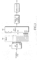
- FIG. 1 illustrates a transmitter in a Localized FDMA (LFDMA) system, which is a type of SC-FDMA system. While the transmitter is configured so as to use Discrete Fourier Transform (DFT) and Inverse Fast Fourier Transform (IFFT) in FIG. 1 , any other configuration is available to the transmitter.
- LFDMA Localized FDMA
- IFFT Inverse Fast Fourier Transform
- the LFDMA transmitter further includes a DFT precoder 101 at the front end of an IFFT processor 102 that is used for multi-carrier transmission in an OFDM transmitter.
- Transmission (TX) modulated symbols 103 are provided in blocks to the DFT precoder 101.
- DFT outputs are mapped to IFFT inputs in a band including successive subcarriers.
- a mapper 104 functions to map the transmission modulated symbols to an actual frequency band.
- FIG. 2 illustrates a data transmission from User Equipments (UEs) in their allocated resources in a conventional SC-FDMA system.
- UEs User Equipments
- one Resource Unit (RU) 201 is defined by one or more subcarriers in frequency and one or more SC-FDMA symbols in time. For data transmission, two RUs indicated by the diagonal lines are allocated to UE1 and three RUs indicated by the dots are allocated to UE2.
- the RUs in which UE1 and UE2 transmit data are fixed in time and successive in set frequency bands.
- This scheme of resource allocation or data transmission selectively allocates frequency resources that offer a good channel status to each UE, to thereby maximize system performance with limited system resources.
- the blocks with the diagonal lines offer better radio channel characteristics to UE1 than in other frequency bands, whereas the dotted blocks offer better radio channel characteristics to UE2 than in other frequency bands.
- the selective allocation of resources with a better channel response is called frequency selective resource allocation or frequency selective scheduling.
- the frequency selective scheduling applies to downlink data transmission from the Node B to the UE.
- the RUs marked with diagonal lines and dots represent resources in which the Node B transmits data to UE1 and UE2, respectively.
- the frequency selective scheduling is not always effective. For a UE that moves fast and thus experiences a fast change in channel status, the frequency selective scheduling is not easy.
- a Node B scheduler allocates a frequency band in a relatively good channel status to a UE at a given time, the UE is placed in an already significantly changed channel environment when it receives resource allocation information from the Node B and is to transmit data in the allocated resources.
- the selected frequency band does not ensure a relatively good channel status for the UE.
- VoIP Voice over Internet Protocol
- FIG. 3 illustrates frequency hopping in a conventional FDMA system.
- frequency resources allocated to a UE for data transmission change in time.
- the frequency hopping has the effect of randomizing channel quality and interference during data transmission.
- the data As data is transmitted in frequency resources that vary in time, the data has different channel characteristics and is interfered by a different UE in a neighbor cell at each time point, thus achieving diversity.
- the frequency hopping is not viable when RUs hop in independent patterns in the SC-FDMA system as illustrated in FIG. 3 .
- RUs 301 and 302 are allocated to different UEs, it does not matter.
- both the RUs 301 and 302 are allocated to a single UE, they hop to the positions of RUs 303 and 304 by frequency hopping at the next transmission point. Since the RUs 303 and 304 are not successive, the UE cannot transmit data in these two RUs.
- mirroring is disclosed to substitute for the frequency hopping, and is illustrated in FIG. 4 .
- an RU moves symmetrically with respect to the center frequency of a total frequency band available for data transmission.
- an RU 401 is mirrored to an RU 403 and an RU 402 to an RU 404 at the next transmission time in Cell A.
- an RU 405 is mirrored to an RU 406 at the next transmission time in Cell B. The mirroring enables successive RUs to successively hop, thereby satisfying the single carrier property during frequency hopping.
- a shortcoming with the frequency hopping with frequency diversity is that the hopping pattern is fixed because there is no way to move RUs without mirroring with respect to a center frequency. This means that frequency diversity is achieved to a certain degree but interference randomization is difficult. As an RU hopped to the opposite returns to its original position by mirroring, only one RU hopping pattern is available. Therefore, even when a plurality of cells exists, each cell cannot have a different pattern.
- the UE 402 marked with dots is allocated to a UE in Cell A and the RU 405 marked with single-diagonal lines is allocated to a UE in Cell B for a period of time, the UE of Cell A interferes with the UE of Cell B because only one hopping pattern is available in the mirroring scheme. If the UE of Cell B is near Cell A, it causes substantial interference to UEs in Cell A. As a result, the UE of Cell A using RUs marked with dots suffers from reception quality degradation.
- An aspect of the present invention is to address at least the problems and/or disadvantages and to provide at least the advantages described below. Accordingly, an aspect of the present invention is to provide a method and apparatus for allocating resources to randomize interference between neighbor cells when mirroring is adopted to achieve frequency diversity.
- An aspect of the present invention is to provide a method for determining whether to turn on or off mirroring at each hopping time according to a different mirroring on/off pattern for each cell, and a transmitting/receiving apparatus using the same.
- An aspect of the present invention is to provide a method for determining whether to turn or off frequency hopping and mirroring at each hopping time according to a different pattern for each cell, and a transmitting/receiving apparatus using the same, when frequency hopping can be supported to increase a frequency diversity effect.
- a method for allocating resources to a UE in an SC-FDMA communication system in which is determined on a cell basis whether to turn or off inter-subband hopping and whether to turn on or off mirroring for a resource unit for the UE on a frequency axis along which at least two subbands are defined, at each hopping time, and a resource unit is selected by selectively performing inter-subband hopping and mirroring on the resource unit for the UE according to the determination and allocated to the UE.
- a method for being allocated resources from a Node B in an SC-FDMA communication system in which it is determined whether to turn or off inter-subband hopping and whether to turn on or off mirroring for a resource unit for the UE on a frequency axis along which at least two subbands are defined, at each hopping time, a resource unit is selected by selectively performing inter-subband hopping and mirroring on the resource unit for the UE according to the determination, and data is transmitted in the selected resource unit to the Node B.
- an apparatus of a Node B for allocating resources to UEs in an SC-FDMA communication system in which a scheduler determines on a cell basis whether to turn or off inter-subband hopping and whether to turn on or off mirroring for resource units for the UEs on a frequency axis along which at least two subbands are defined, at each hopping time, and selects resource units to be allocated for the UEs by selectively performing inter-subband hopping and mirroring on the resource units for the UEs according to the determination, a mapper separates data received from the UEs according to information about the selected resource units received from the scheduler, and a decoder decodes the separated data.
- an apparatus of a UE for transmitting data to a Node B in an SC-FDMA communication system in which a data transmission controller determines on a cell basis whether to turn or off inter-subband hopping and whether to turn on or off mirroring for a resource unit for the UE on a frequency axis along which at least two subbands are defined, at each hopping time, and a mapper maps data to a resource unit selected by selectively performing inter-subband hopping and mirroring on the resource unit for the UE according to the determination and transmits the mapped data to the Node B.
- Preferred embodiments of the present invention provide a method for increasing the randomization of interference between cells when data is transmitted in a different RU at each predetermined time by a general frequency hopping or mirroring scheme to achieve frequency diversity while satisfying the single carrier property in an uplink SC-FDMA system.
- data channels are defined as follows.
- Frequency Scheduling (FS) band a set of RUs allocated by frequency selective scheduling. They are successive or scattered.
- Frequency Hopping (FH) band a set of RUs transmitted to achieve frequency diversity. These RUs are not allocated by frequency selective scheduling. They are successive or scattered.
- An FH band can include one or more sub-FH bands.
- RUs are symmetrically hopped from left to right and from right to left with respect to a center subcarrier or a center RU in a sub-FH band.
- Hopping time a time at which an allocated RU hops or is mirrored. Depending on how hopping or mirroring applies, the RU has the following period.
- Embodiment 1 provides a method for turning mirroring on or off according to a different mirroring on/off pattern for each cell. Using different mirroring on/off patterns for different cells as much as possible and decreasing the probability of mirroring-on in cells at the same time maximize the effect of randomizing interference between cells.
- FIGs. 5A and 5B illustrate a method according to the first embodiment of the present invention.
- FIG. 5A illustrates slot-based mirroring irrespective of HARQ and
- FIG. 5B illustrates independent mirroring for each HARQ process.
- the hopping period is a slot.
- mirroring is performed at each hopping time in a pattern 503 of on, on, on, off, on, off, off, off ... in Cell A, and in a pattern 512 of on, off, on, on, off, off, on, on, ... in Cell B.
- an RU 504 is allocated to UE A at a hopping time k. Since mirroring is on for UE A at the next hopping time (k+1), UE A uses an RU 505 in slot (k+1). Mirroring is off at hopping time (k+3) and thus UE A transmits data in an RU 506 identical to an RU used in the previous slot (k+2) in slot (k+3). Similarly, since mirroring is off at hopping time (k+6), UE A transmits data in an RU 507 identical to an RU transmitted in the previous slot (k+5) in slot (k+6).
- an RU 508 is allocated to UE B in slot k in Cell B. Since mirroring is off at the next hopping time (k+1), UE B uses an RU 509 in slot (k+1). At hopping time (k+3), mirroring is on and thus UE B uses an RU 510 in slot (k+3). Similarly, since mirroring is on at hopping time (k+6), UE B uses an RU 511 in slot (k+6).
- Mirroring is on or off at each hopping time in a different pattern in each cell. Therefore, while UEs within different cells may use the same RU in a given slot, the probability of their using the same RU in the next slot decreases due to the use of different mirroring on/off patterns.
- the RUs 504 and 508 are allocated respectively to UE A in Cell A and UE B in Cell B in slot k. If UE B is near Cell A, UE A is likely to be significantly interfered with by UE B.
- UE A since UE A turns on mirroring at the next hopping time (k+1), UE A transmits data in the RU 505 in slot (k+1), whereas mirroring is off for UE B and thus UE B transmits data in the RU 509 identical to that used in the previous slot. Thus, UE A and UE B use different RUs in slot (k+1).
- the mirroring method illustrated in FIG. 5B is similar to that illustrated in FIG. 5A in that different cells use different mirroring on/off patterns and the former differs from the latter in that in FIG. 5B , an RU is mirrored with respect to an RU in the same HARQ process rather than with respect to an RU in the previous slot, as in FIG. 5A .
- RTT represents Round Trip Time, defined as the initial transmission time when a response for transmitted data is Negative ACKnowledgment (NACK) and a response for retransmitted data is an ACK.
- data transmitted in RUs 518 and 519 are retransmission versions of data transmitted in RUs 516 and 517 or belong to the same HARQ process as the data transmitted in the RUs 516 and 517.
- the HARQ RTT-based mirroring facilitates defining a mirroring on/off pattern in which different RUs are used for initial transmission and retransmission. Despite this advantage, management of a different mirroring on/off pattern for each HARQ process increases complexity. In this context, a mirroring on/off pattern is determined as follows.
- a cell-specific seed is used and to achieve the same PN sequence, UEs within the same cell should receive the same timing information.
- the timing information can be represented as the difference between an absolute time and a current time or as a common time frame count such as a System Frame Number (SFN).
- SFN System Frame Number
- FIG. 6 illustrates an operation for determining mirroring on/off in a UE according to the first embodiment of the present invention.
- a Node B can perform the same operation.
- the UE when the Node B schedules an RU for the UE, the UE generates a PN sequence value in step 601 and checks the PN sequence value in step 602. If the PN sequence value is 0, the UE determines to turn mirroring off in step 604. If the PN sequence value is 1, the UE determines to turn mirroring on in step 603. In step 605, the UE determines an RU position for the next data transmission according to the mirroring-on/off determined in step 603 or 604. The UE transmits data in the determined RU in step 606.
- Mirroring results in a symmetrical RU hopping with respect to the center of a total FH band.
- a new RU for use in the next slot can be detected based on information about an RU used in a previous slot.
- the mirroring base is an RU used in the previous slot in FIG. 5A and an RU used in the previous slot of the same HARQ process in FIG. 5B .
- H ( r ) denotes an RU to which the mirroring base is mirrored in a slot.
- N FH denotes the total number of RUs in the FH band.
- FIG. 7 illustrates the UE according to the first embodiment of the present invention.
- a data symbol generator 703 generates data symbols to be transmitted.
- the amount of data transmittable in each Transmission Time Interval (TTI) is determined by Node B scheduling.
- a Serial-to-Parallel (S/P) converter 704 converts the sequence of the data symbols to parallel symbol sequences.
- a DFT processor 705 converts the parallel symbol sequences to frequency signals, for SC-FDMA transmission.
- a DFT size is equal to the number of the data symbols generated from the data symbol generator 703.
- a mapper 706 maps the frequency signals to frequency resources allocated to the UE based on RU information received from a data transmission controller 702.
- the data transmission controller 702 generates the RU information based on scheduled RU information and mirroring on/off information.
- Each cell has a different mirroring on/off pattern according to a PN sequence.
- a PN sequence generator 701 is required.
- An RU to be used is decided using the output of the PN sequence generator 701 in the aforementioned method.
- An IFFT processor 707 converts the mapped signals to time signals.
- a Parallel-to-Serial (P/S) converter 708 converts the time signals to a serial signal for transmission.
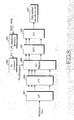
- FIG 8 illustrates the Node B according to the first embodiment of the present invention.
- an S/P converter 807 converts a received signal to parallel signals and an FFT processor 806 converts the parallel signals to frequency signals.
- a demapper 805 demaps the frequency signals for different UEs based on RU allocation information about each UE determined by an uplink scheduler 802.
- the uplink scheduler 802 generates the RU information for each UE using scheduled RU information and mirroring on/off information based on a mirroring on/off pattern. Since each cell has a different mirroring on/off pattern, a PN sequence generator 801 is needed.
- An RU from which data is to be extracted is decided based on the output of the PN sequence generator 801 in the aforedescribed method.
- An IDFT processor 804 converts the demapped signal of an intended UE, UE 1 to time signals.
- a P/S converter 808 converts the time signals to a serial signal.
- a data symbol decoder 803 demodulates data received from UE
- Inter-sub-FH band hopping on/off is combined with mirroring on/off and the position of an RU for data transmission is determined by selecting one of the combinations such that each cell has a different pattern. That is, the resources of a total system frequency band are divided into an FH band and an FS band, and a channel structure which offers a sufficient frequency hopping gain in the FH band and achieves a sufficiently available frequency band in the FS band is disclosed.
- FIG. 9 illustrates the channel structure according to the second embodiment of the present invention.
- sub-FH bands 901 and 903 are defined at either side of a total frequency band and the center frequency band between the sub-FH bands 901 and 903 is defined as an FS band 902.
- UEs using the FS band 902 can hop to the sub-FH bands 901 and 903, thereby achieving a sufficient frequency hopping gain.
- a maximum data rate can be increased.
- inter-sub-FH band hopping is on/off and mirroring is on/off at each hopping time according to a cell-specific pattern.
- Table 1 Four combinations of inter-sub-FH band hopping on/off and mirroring on/off are available as illustrated in Table 1. At each hopping time, one of the combinations is selected and hopping and/or mirroring apply to each cell using the selected combination in a different pattern. Table 1 combination FH band hopping Mirroring 1 On On 2 Off Off 3 Off On 4 On Off
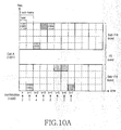
- FIGs. 10A to 10D illustrate the method according to the second embodiment of the present invention.
- FIGs. 10A and 10B are based on the assumption that intra-TTI hopping is supported in cells 1001 and 1007 (Cell A and Cell B). Therefore, the hopping period is a slot.
- combinations are selected in the order of 3-1-4-3-2-1-2-3 for Cell A and in the order of 3-4-2-1-3-2-1-4 for Cell B.
- Cell A uses an RU 1002 at hopping time k, it selects an RU 1005 by inter-sub-FH band hopping and mirroring according to combination 1 at hopping time (k+1). At the next hoping time (k+2), Cell A performs only inter-sub-FH band hopping without mirroring according to combination 4 and thus selects an RU 1003. Since combination 2 is set for hopping time (k+4), Cell A selects an RU 1004 without inter-sub-FH band hopping and mirroring.
- Cell B selects the same RU 1008 used for Cell A at hopping time k.
- Cell B selects an RU 1009 through inter-sub-FH band hopping only without mirroring according to combination 4, as compared to Cell A that selects the RU 1005 through both inter-sub-FH band hopping and mirroring according to combination 1.
- another UE within Cell B may use the same RU as the RU 1005 in slot (k+1)
- interference from a different UE at each time rather than collision with the same UE offers a better interference randomization gain.
- inter-sub-FH band hopping and mirroring are performed with respect to an RU used for the previous data transmission of the same HARQ process, instead of an RU used at the previous hopping time.
- an RU 1013 is selected at hopping time k by inter-sub-FH band hopping of an RU 1014 used for the previous data transmission of the same HARQ process, not of an RU used at hopping time (k-1).
- Combination 4 is set for hopping time k, which means inter-sub-FH band hopping is on and mirroring is off with respect to the RU 1014.
- the RU 1013 is selected at hopping time k.
- the RU 1013 is inter-sub-FH band-hopped and mirrored to an RU 1012.
- a cell-specific seed is used and to achieve the same PN sequence, UEs within the same cell should receive the same timing information.
- the timing information can be represented as the difference between an absolute time and a current time or as a common time frame count such as an SFN.
- FIG. 11 illustrates an operation of the UE according to the second embodiment of the present invention. The same operation applies to the Node B when it receives data from the UE.
- the UE when the Node B schedules a specific RU for the UE, the UE generates a PN sequence value in step 1101 and determines whether the PN sequence value is 1, 2, 3, or 4 in step 1102. If the PN sequence value is 1, the UE selects a combination of mirroring-on and inter-sub-FH band hopping-on in step 1103. If the PN sequence value is 2, the UE selects a combination of mirroring-off and inter-sub-FH band hopping-off in step 1104. If the PN sequence value is 3, the UE selects a combination of mirroring-off and inter-sub-FH band hopping-on in step 1105.
- the UE selects a combination of mirroring-on and inter-sub-FH band hopping-off in step 1106.
- the UE determines an RU for data transmission by mirroring and/or hopping according to the selected combination.
- the UE transmits data in the determined RU in step 1108.
- a transmitter and a receiver according to the second embodiment of the present invention have the same configurations as those according to the first embodiment of the present invention, except that the PN sequence generators 701 and 802 generate one of four values 1 to 4 and provide the generated value to the data transmission controller 702 and the uplink scheduler 802 so as to determine the position of an RU.
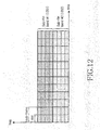
- FIG. 12 illustrates a channel structure according to a third embodiment of the present invention.
- a method for determining mirroring on/off according to a different pattern for each cell.
- the use of different mirroring on/off patterns for different cells decreases the probability of performing mirroring at the same time in the different cells, thus resulting in maximized randomization of inter-cell interference.
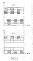
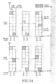
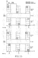
- FIGs. 13 and 14 illustrate a method according to the third embodiment of the present invention. Specifically, FIG. 13 illustrates a mirroring method independent of HARQ and FIG. 14 illustrates a method for performing mirroring on an HARQ process basis.
- the hopping period is a slot.
- Mirroring is performed at each hopping time in a pattern 1310 of on, on, off, off, on, off, off, off ... in Cell A, and in a pattern 1320 of on, off, off, on, off, off, on, on, ... in Cell B.
- an RU 1302 in sub-FH band #1 is allocated to a UE at hopping time k in Cell A, it hops to sub-FH band #2 because inter-sub-FH band hopping always applies and is mirrored according to the mirroring pattern 1310.
- the UE uses an RU 1303 in slot (k+1).
- the UE selects an RU 1304 through hopping to sub-FH band #1 and mirroring-off. Since hopping to sub-FH band #2 occurs and mirroring is off at the next hopping time (k+3), the UE uses an RU 1305 in slot (k+3).
- a different mirroring on/off pattern is defined for Cell B. Specifically, mirroring is on/off in a different manner at each hopping time for each cell.
- Cell A and Cell B may select the same RU at a given hopping time
- the third embodiment of the present invention reduces the probability of selecting the same RU at the next hopping time in the two cells.
- UE A when the same RUs 1302 and 1312 are allocated respectively to UE A in Cell A and UE B in Cell B for a period of time, if UE B is near Cell A, UE A is likely to be significantly interfered with by UE B at hopping time k.
- Cell A performs both inter-sub-FH band hopping and mirroring at the next hopping time (k+ 1), UE A transmits data in the RU 1303 in slot (k+1), whereas inter-sub-FH band hopping is on and mirroring is off for UE B and thus UE B transmits data in an RU 1313 in slot (k+1).
- UE A and UE B use different RUs in slot (k+1), thus avoiding continual interference from the same UE.
- the mirroring method illustrated in FIG. 14 is similar to that illustrated in FIG. 13 in that mirroring follows inter-sub-FH band hopping and different cells use different mirroring on/off patterns, and the former differs from the latter in that an RU is mirrored with respect to an RU in the same HARQ process in FIG. 14 , rather than with respect to an RU used at the previous transmission time as in FIG. 13 .
- a UE in a cell 1401 uses an RU 1407 to which an RU 1406 used in slot (k+1) of the same HARQ process is - mirrored, instead of an RU to which an RU used in the previous slot (k+RTT-1) is mirrored.
- the HARQ RTT-based mirroring facilitates defining a mirroring on/off pattern in which different RUs are used for initial transmission and retransmission, thereby maximizing an interference diversity effect.
- the UE determines mirroring on/off in the same manner as in the first embodiment of the present invention, except that inter-sub-FH band hopping occurs all the time in selecting an RU.
- Equation (2) a hopping pattern formula is given as Equation (2), for example.
- the UE is aware of a resource block to be used at each transmission time using the hopping pattern formula and the index of a scheduled resource block.
- N o ⁇ N_RB M ⁇
- N s N_RB - M - 1 ⁇ N o
- h(i) denotes a cyclic shift degree, being one of ⁇ 0, 1, ..., M ⁇ selected according to a bit value of a random sequence.
- h(0) 0.
- m(i) is a parameter that determines mirroring on/off at hopping time (i), being one of ⁇ 0, 1 ⁇ .
- Equation (2) the offset O s at the scheduling time of the scheduled resource block is first calculated by the first line of Equation (2).
- O s indicates how far a cyclically shifted resource block is spaced from the cyclic shift reference point.
- O s is introduced for the following reason.
- the subbands do not have the same amount of resources, causing failed inter-subband hopping. Therefore, subbands are formed such that one subband has a fewer number of resource blocks N o than the number N s of resources blocks of each of the other subbands and O s is used to indicate the subband having the fewer number of resource blocks to the UE in the third embodiment of the present invention.
- subbands can be configured so that a first subband has four resource blocks and each of the other subbands has six resource blocks.
- O s is less than 4
- the UE is aware that the scheduled resource block resides in the smaller subband.
- a plurality of subbands each have N s resource blocks and a plurality of remaining subbands each have N o resource blocks. For example, if four subbands are given, two subbands each have five resources blocks and the other two subbands each include six resource blocks. This case can be easily realized by modifying the conditional sentences of Equation (2) that indicate a scheduled subband using an offset.
- a fourth embodiment of the present invention discloses a limited use of a method for generating a random mirroring pattern and determining mirroring on/off according to the random mirroring pattern, when needed.
- mirroring is always on at each hopping time for one of the two hopping schemes and mirroring is on/off in a random mirroring on/off pattern for the other hopping scheme.
- FIG. 15 illustrates a method for always turning on mirroring for inter-subframe hopping and determining mirroring on/off according to a random mirroring on/off pattern for intra-subframe hopping according to the fourth embodiment of the present invention.
- sub-FH bands are positioned at either side of a system frequency band and an FS band is interposed at the center frequency band between the sub-FH bands.
- an RU hops between the sub-FH bands at each hopping time as in the third embodiment of the present invention.
- mirroring occurs at each intra-subframe hopping time according to a pattern of on, off, off, ... in a cell 1500 (Cell A) and according to a pattern of off, off, on, ... in a cell 1520 (Cell B).
- an RU 1502 When an RU 1502 is allocated to a UE at hopping time (k-RTT) in Cell A, the UE selects an RU 1503 by mirroring according to the mirroring on/off pattern at the next hopping time (k-RTT+1). At hopping time k being the next transmission time of the same HARQ process, mirroring is always on.
- an RU 1504 is selected by mirroring the RU 1502 used in the first slot (k-RTT) of the previous HARQ transmission time. Since mirroring is off according to the mirroring on/off pattern at the next hopping time (k+1), the UE selects an RU 1505.
- hopping time being the next transmission time of the same HARQ process
- mirroring is always on.
- the RU 1504 is mirrored to an RU 1506. Since mirroring is off according to the mirroring on/off pattern at the next hopping time (k+RTT+1), the UE selects an RU 1507.
- an RU hops to another sub-FH band by turning on/off mirroring according to a random mirroring on/off pattern at each intra-subframe hopping time in Cell B. That is, if an RU 1508 is used in slot (k-RTT), an RU 1509 is selected by turning off mirroring according to the mirroring on/off pattern at the next hopping time (k-RTT+1). Since mirroring is performed with respect to the RU 1508 used at the previous transmission time of the same HARQ process at the next HARQ transmission time, an RU 1510 is selected at hopping time k. At hopping time (k+1), mirroring is off according to the mirroring on/off pattern and thus an RU 1511 is selected.
- an RU 1512 is selected at hopping time (k+RTT).
- hopping time (k+RTT+1) mirroring is on according to the mirroring on/off pattern and thus an RU 1513 is selected.
- the present invention advantageously randomizes inter-cell interference, increasing a frequency diversity effect, by turning on or off mirroring at each hopping time according to a different mirroring on/off pattern in each cell.
Landscapes
- Engineering & Computer Science (AREA)
- Signal Processing (AREA)
- Computer Networks & Wireless Communication (AREA)
- Mobile Radio Communication Systems (AREA)
Applications Claiming Priority (4)
| Application Number | Priority Date | Filing Date | Title |
|---|---|---|---|
| KR20070002657 | 2007-01-09 | ||
| KR1020070058331A KR20080065518A (ko) | 2007-01-09 | 2007-06-14 | 단일 캐리어 주파수 분할 다중 접속 방식시스템에서 주파수호핑 방법 및 장치 |
| KR1020070080204A KR20080065523A (ko) | 2007-01-09 | 2007-08-09 | 단일 캐리어 주파수 분할 다중 접속 방식시스템에서 주파수호핑 방법 및 장치 |
| KR1020070126476A KR100942289B1 (ko) | 2007-01-09 | 2007-12-07 | 단일 캐리어 주파수 분할 다중 접속 시스템에서의 자원 할당 방법 및 장치 |
Publications (3)
| Publication Number | Publication Date |
|---|---|
| EP1944875A2 true EP1944875A2 (de) | 2008-07-16 |
| EP1944875A3 EP1944875A3 (de) | 2010-07-21 |
| EP1944875B1 EP1944875B1 (de) | 2018-11-14 |
Family
ID=39273539
Family Applications (2)
| Application Number | Title | Priority Date | Filing Date |
|---|---|---|---|
| EP08000316.3A Active EP1944875B1 (de) | 2007-01-09 | 2008-01-09 | Vorrichtung und Verfahren zum Zuweisen von Ressourcen in einem Einzelträgerfrequenzteilungs-Mehrfachzugriffssystem |
| EP08000317.1A Active EP1944876B1 (de) | 2007-01-09 | 2008-01-09 | Vorrichtung und Verfahren zum Zuweisen von Ressourcen in einem Einzelträgerfrequenzteilungs-Mehrfachzugriffssystem |
Family Applications After (1)
| Application Number | Title | Priority Date | Filing Date |
|---|---|---|---|
| EP08000317.1A Active EP1944876B1 (de) | 2007-01-09 | 2008-01-09 | Vorrichtung und Verfahren zum Zuweisen von Ressourcen in einem Einzelträgerfrequenzteilungs-Mehrfachzugriffssystem |
Country Status (3)
| Country | Link |
|---|---|
| US (8) | US9072096B2 (de) |
| EP (2) | EP1944875B1 (de) |
| WO (2) | WO2008084981A1 (de) |
Cited By (2)
| Publication number | Priority date | Publication date | Assignee | Title |
|---|---|---|---|---|
| WO2010053686A1 (en) * | 2008-11-04 | 2010-05-14 | Qualcomm Incorporated | Transmission with hopping for peer-to-peer communication |
| EP2485552A4 (de) * | 2009-10-16 | 2016-08-24 | Zte Corp | Verfahren und system zum planen der physischen ressourcen für die frequenz auf frequenzsprungbasis |
Families Citing this family (28)
| Publication number | Priority date | Publication date | Assignee | Title |
|---|---|---|---|---|
| US10084627B2 (en) | 2006-07-10 | 2018-09-25 | Qualcomm Incorporated | Frequency hopping in an SC-FDMA environment |
| WO2008039034A2 (en) | 2006-09-29 | 2008-04-03 | Lg Electronics Inc. | Methods for allocating resources to uplink control channel |
| EP1944875B1 (de) | 2007-01-09 | 2018-11-14 | Samsung Electronics Co., Ltd. | Vorrichtung und Verfahren zum Zuweisen von Ressourcen in einem Einzelträgerfrequenzteilungs-Mehrfachzugriffssystem |
| GB2446197A (en) | 2007-02-05 | 2008-08-06 | Nec Corp | Frequency-hopping method and mobile communication system |
| KR101448653B1 (ko) * | 2007-10-01 | 2014-10-15 | 엘지전자 주식회사 | 주파수 호핑 패턴 및 이를 이용한 상향링크 신호 전송 방법 |
| US20090135754A1 (en) * | 2007-11-27 | 2009-05-28 | Qualcomm Incorporated | Interference management in a wireless communication system using overhead channel power control |
| JP5142379B2 (ja) * | 2008-03-19 | 2013-02-13 | パナソニック株式会社 | 移動局装置及び基地局装置、並びに無線通信システムの通信制御方法 |
| KR101700184B1 (ko) * | 2008-07-01 | 2017-02-13 | 엘지전자 주식회사 | 무선 통신을 위한 향상된 자원 입도를 갖는 퍼뮤테이션 장치 및 방법 |
| KR101495289B1 (ko) * | 2008-07-03 | 2015-02-25 | 삼성전자주식회사 | 광대역 무선통신 시스템에서 주파수 오버레이 방식을 위한자원 할당 장치 및 방법 |
| EP2334114B1 (de) * | 2008-09-22 | 2016-10-12 | Sharp Kabushiki Kaisha | Drahtloses kommunikationssystem, basisstationsvorrichtung, mobilstationsvorrichtung und drahtloses kommunikationsverfahren |
| US8811371B2 (en) * | 2008-09-23 | 2014-08-19 | Qualcomm Incorporated | Transmit diversity scheme for uplink data transmissions |
| KR101156164B1 (ko) * | 2008-12-22 | 2012-06-18 | 한국전자통신연구원 | 주파수 집합 통신 환경에서의 단말 및 기지국, 이를 이용한호 접속 처리 방법 |
| KR101534169B1 (ko) | 2008-12-23 | 2015-07-07 | 삼성전자 주식회사 | 주파수 도약 모드로 동작 중인 무선 통신 시스템의 주파수 할당 방법 및 이를 위한 장치 |
| US9374131B2 (en) | 2009-01-28 | 2016-06-21 | Qualcomm Incorporated | Frequency hopping in a wireless communication network |
| US9673952B2 (en) | 2009-04-10 | 2017-06-06 | Qualcomm Inc. | Method and apparatus for supporting user equipments on different system bandwidths |
| CA2761636C (en) * | 2009-05-29 | 2016-12-06 | Panasonic Corporation | Wireless communication apparatus and frequency hopping method |
| US9276710B2 (en) | 2009-12-21 | 2016-03-01 | Qualcomm Incorporated | Method and apparatus for resource allocation with carrier extension |
| RU2436248C1 (ru) * | 2010-06-18 | 2011-12-10 | Открытое акционерное общество "Концерн "Созвездие" | Способ передачи и приема цифровой информации |
| US8995539B2 (en) * | 2010-07-13 | 2015-03-31 | Qualcomm Incorporated | Methods and apparatus for selecting and using communications resources in a communication system |
| US9131395B2 (en) * | 2010-09-08 | 2015-09-08 | Broadcom Corporation | Acknowledgment and/or receiver recovery mechanisms for scheduled responses within multiple user, multiple access, and/or MIMO wireless communications |
| GB2506418A (en) * | 2012-09-28 | 2014-04-02 | Sony Corp | A base station allocates a centre frequency for an OFDM virtual channel in dependence upon a terminal's bandwidth capability |
| GB2530502A (en) * | 2014-09-23 | 2016-03-30 | Nec Corp | Communication system |
| JP2016127439A (ja) * | 2015-01-05 | 2016-07-11 | 富士通株式会社 | 受信装置、及び、受信方法 |
| US9860030B2 (en) * | 2015-03-26 | 2018-01-02 | Samsung Electronics Co., Ltd. | Transmission of system information for low cost user equipment |
| CN113037448B (zh) * | 2015-08-07 | 2023-11-21 | 纽瑞科姆有限公司 | 用于wlan系统中的多用户传输的控制信息 |
| US10243929B2 (en) | 2016-03-30 | 2019-03-26 | Qualcomm Incorporated | Uplink control channel scheduling for jamming resilience |
| US10667282B2 (en) | 2017-07-11 | 2020-05-26 | Qualcomm Incorporated | Uplink hopping pattern modes for hybrid automatic repeat request (HARQ) transmissions |
| US11882581B2 (en) | 2021-02-16 | 2024-01-23 | Cisco Technology, Inc. | Wireless mirror device for mitigating multipath interference between transmitter and receiver devices using distinct transmit frequency |
Family Cites Families (24)
| Publication number | Priority date | Publication date | Assignee | Title |
|---|---|---|---|---|
| GB9102220D0 (en) | 1991-02-01 | 1991-03-20 | British Telecomm | Method and apparatus for decoding video signals |
| CA2299568A1 (en) | 1999-03-11 | 2000-09-11 | Lucent Technologies Inc. | Orthogonal frequency division multiplexing based spread spectrum multiple access system using directional antenna |
| US6714526B2 (en) * | 2000-12-15 | 2004-03-30 | Qualcomm Incorporated | Method and apparatus for code assignment in a spread spectrum wireless communication system |
| US6580920B2 (en) | 2001-06-05 | 2003-06-17 | Nokia Mobile Phones Ltd. | System for adjusting gain of a mobile station during an idle period of the serving base station |
| CN1152493C (zh) | 2002-06-20 | 2004-06-02 | 上海交通大学 | 正交频分复用通信系统的峰平比抑制方法 |
| KR100470401B1 (ko) * | 2002-12-24 | 2005-02-05 | 한국전자통신연구원 | 그룹화 최유도 검출을 이용한 무선 통신 시스템 및 방법 |
| US20050163194A1 (en) * | 2004-01-28 | 2005-07-28 | Qualcomm Incorporated | Interference estimation in a wireless communication system |
| US7724777B2 (en) * | 2004-06-18 | 2010-05-25 | Qualcomm Incorporated | Quasi-orthogonal multiplexing for a multi-carrier communication system |
| WO2006004968A2 (en) | 2004-06-30 | 2006-01-12 | Neocific, Inc. | Methods and apparatus for power control in multi-carrier wireless systems |
| JP5038134B2 (ja) | 2004-07-01 | 2012-10-03 | クゥアルコム・インコーポレイテッド | スケーラブルなビデオ符号化において、フレームレートアップ変換技術を使用する方法及び装置 |
| JP4684628B2 (ja) | 2004-11-16 | 2011-05-18 | Kddi株式会社 | サブキャリア割当装置およびマルチキャリア無線通信システム |
| EP1820314A4 (de) * | 2004-12-08 | 2013-01-09 | Korea Electronics Telecomm | Sender und frequenzsprungverfahren dafür |
| US8942639B2 (en) | 2005-03-15 | 2015-01-27 | Qualcomm Incorporated | Interference control in a wireless communication system |
| US8730877B2 (en) * | 2005-06-16 | 2014-05-20 | Qualcomm Incorporated | Pilot and data transmission in a quasi-orthogonal single-carrier frequency division multiple access system |
| KR100918729B1 (ko) | 2006-01-09 | 2009-09-24 | 삼성전자주식회사 | 단반송파 주파수 분할 다중 접속 시스템에서 역방향 제어정보와 데이터의 시간적 다중화 방법 및 장치 |
| US20070211656A1 (en) | 2006-01-09 | 2007-09-13 | Samsung Electronics Co., Ltd. | Method and apparatus for time multiplexing uplink data and uplink signaling information in an SC-FDMA system |
| KR101196897B1 (ko) | 2006-01-20 | 2012-11-01 | 에릭슨 엘지 주식회사 | 무선통신 시스템 내에서 랜덤 액세스 채널에 주파수 대역을 할당하는 방법 및 장치와, 그의 랜덤 액세스 채널 상에서의 신호 송수신 장치 및 방법 |
| US8457076B2 (en) | 2006-01-20 | 2013-06-04 | Lg-Ericsson Co., Ltd. | Apparatus and method for transmitting and receiving a RACH signal in SC-FDMA system |
| CN100464543C (zh) | 2006-01-27 | 2009-02-25 | 东南大学 | 兼容的单载波正交频分多址信号发送方法 |
| US10084627B2 (en) | 2006-07-10 | 2018-09-25 | Qualcomm Incorporated | Frequency hopping in an SC-FDMA environment |
| US20080095277A1 (en) * | 2006-10-19 | 2008-04-24 | Lixin Cheng | Transmission and detection of preamble signal in OFDM communication system |
| US8270424B2 (en) * | 2006-11-01 | 2012-09-18 | Alcatel Lucent | Method of signaling allocated resources |
| KR20080065518A (ko) | 2007-01-09 | 2008-07-14 | 삼성전자주식회사 | 단일 캐리어 주파수 분할 다중 접속 방식시스템에서 주파수호핑 방법 및 장치 |
| EP1944875B1 (de) | 2007-01-09 | 2018-11-14 | Samsung Electronics Co., Ltd. | Vorrichtung und Verfahren zum Zuweisen von Ressourcen in einem Einzelträgerfrequenzteilungs-Mehrfachzugriffssystem |
-
2008
- 2008-01-09 EP EP08000316.3A patent/EP1944875B1/de active Active
- 2008-01-09 US US11/971,692 patent/US9072096B2/en active Active
- 2008-01-09 WO PCT/KR2008/000132 patent/WO2008084981A1/en not_active Ceased
- 2008-01-09 EP EP08000317.1A patent/EP1944876B1/de active Active
- 2008-01-09 US US11/971,540 patent/US9072095B2/en active Active
- 2008-01-09 WO PCT/KR2008/000131 patent/WO2008084980A1/en not_active Ceased
-
2014
- 2014-07-14 US US14/330,809 patent/US9510348B2/en active Active
- 2014-12-15 US US14/570,411 patent/US9521672B2/en active Active
-
2015
- 2015-06-29 US US14/753,900 patent/US9332542B2/en active Active
- 2015-09-22 US US14/861,733 patent/US9282559B2/en active Active
- 2015-09-22 US US14/861,720 patent/US9603143B2/en active Active
- 2015-09-22 US US14/861,703 patent/US9565678B2/en active Active
Cited By (3)
| Publication number | Priority date | Publication date | Assignee | Title |
|---|---|---|---|---|
| WO2010053686A1 (en) * | 2008-11-04 | 2010-05-14 | Qualcomm Incorporated | Transmission with hopping for peer-to-peer communication |
| US8121097B2 (en) | 2008-11-04 | 2012-02-21 | Qualcomm Incorporated | Transmission with hopping for peer-peer communication |
| EP2485552A4 (de) * | 2009-10-16 | 2016-08-24 | Zte Corp | Verfahren und system zum planen der physischen ressourcen für die frequenz auf frequenzsprungbasis |
Also Published As
| Publication number | Publication date |
|---|---|
| US20080212556A1 (en) | 2008-09-04 |
| US9565678B2 (en) | 2017-02-07 |
| US20160014759A1 (en) | 2016-01-14 |
| EP1944876A3 (de) | 2010-07-21 |
| US9072095B2 (en) | 2015-06-30 |
| EP1944876A2 (de) | 2008-07-16 |
| WO2008084981A1 (en) | 2008-07-17 |
| US20150305018A1 (en) | 2015-10-22 |
| US20150098431A1 (en) | 2015-04-09 |
| US9332542B2 (en) | 2016-05-03 |
| WO2008084980A1 (en) | 2008-07-17 |
| US20140321405A1 (en) | 2014-10-30 |
| US9521672B2 (en) | 2016-12-13 |
| US20080212532A1 (en) | 2008-09-04 |
| EP1944876B1 (de) | 2018-10-24 |
| US9282559B2 (en) | 2016-03-08 |
| EP1944875B1 (de) | 2018-11-14 |
| US9510348B2 (en) | 2016-11-29 |
| US9603143B2 (en) | 2017-03-21 |
| EP1944875A3 (de) | 2010-07-21 |
| US20160014777A1 (en) | 2016-01-14 |
| US20160014776A1 (en) | 2016-01-14 |
| US9072096B2 (en) | 2015-06-30 |
Similar Documents
| Publication | Publication Date | Title |
|---|---|---|
| US9521672B2 (en) | Apparatus and method for allocating resources in a single carrier-frequency division multiple access system | |
| CA2675053C (en) | Apparatus and method for allocating resources in a single carrier-frequency division multiple access system | |
| US10084508B2 (en) | Frequency hopping pattern and method for transmitting uplink signals using the same | |
| US20100118773A1 (en) | User device, base station, and method |
Legal Events
| Date | Code | Title | Description |
|---|---|---|---|
| PUAI | Public reference made under article 153(3) epc to a published international application that has entered the european phase |
Free format text: ORIGINAL CODE: 0009012 |
|
| 17P | Request for examination filed |
Effective date: 20080109 |
|
| AK | Designated contracting states |
Kind code of ref document: A2 Designated state(s): AT BE BG CH CY CZ DE DK EE ES FI FR GB GR HR HU IE IS IT LI LT LU LV MC MT NL NO PL PT RO SE SI SK TR |
|
| AX | Request for extension of the european patent |
Extension state: AL BA MK RS |
|
| PUAL | Search report despatched |
Free format text: ORIGINAL CODE: 0009013 |
|
| AK | Designated contracting states |
Kind code of ref document: A3 Designated state(s): AT BE BG CH CY CZ DE DK EE ES FI FR GB GR HR HU IE IS IT LI LT LU LV MC MT NL NO PL PT RO SE SI SK TR |
|
| AX | Request for extension of the european patent |
Extension state: AL BA MK RS |
|
| AKX | Designation fees paid |
Designated state(s): AT BE BG CH CY CZ DE DK EE ES FI FR GB GR HR HU IE IS IT LI LT LU LV MC MT NL NO PL PT RO SE SI SK TR |
|
| RAP1 | Party data changed (applicant data changed or rights of an application transferred) |
Owner name: SAMSUNG ELECTRONICS CO., LTD. |
|
| STAA | Information on the status of an ep patent application or granted ep patent |
Free format text: STATUS: EXAMINATION IS IN PROGRESS |
|
| 17Q | First examination report despatched |
Effective date: 20161215 |
|
| REG | Reference to a national code |
Ref country code: DE Ref legal event code: R079 Ref document number: 602008057873 Country of ref document: DE Free format text: PREVIOUS MAIN CLASS: H04B0001713000 Ipc: H04B0001714300 |
|
| GRAP | Despatch of communication of intention to grant a patent |
Free format text: ORIGINAL CODE: EPIDOSNIGR1 |
|
| STAA | Information on the status of an ep patent application or granted ep patent |
Free format text: STATUS: GRANT OF PATENT IS INTENDED |
|
| RIC1 | Information provided on ipc code assigned before grant |
Ipc: H04J 13/18 20110101ALN20180606BHEP Ipc: H04L 5/02 20060101ALI20180606BHEP Ipc: H04B 1/715 20110101ALN20180606BHEP Ipc: H04B 1/7143 20110101AFI20180606BHEP |
|
| INTG | Intention to grant announced |
Effective date: 20180622 |
|
| RIC1 | Information provided on ipc code assigned before grant |
Ipc: H04J 13/18 20110101ALN20180611BHEP Ipc: H04B 1/715 20110101ALN20180611BHEP Ipc: H04L 5/02 20060101ALI20180611BHEP Ipc: H04B 1/7143 20110101AFI20180611BHEP |
|
| GRAS | Grant fee paid |
Free format text: ORIGINAL CODE: EPIDOSNIGR3 |
|
| GRAA | (expected) grant |
Free format text: ORIGINAL CODE: 0009210 |
|
| STAA | Information on the status of an ep patent application or granted ep patent |
Free format text: STATUS: THE PATENT HAS BEEN GRANTED |
|
| AK | Designated contracting states |
Kind code of ref document: B1 Designated state(s): AT BE BG CH CY CZ DE DK EE ES FI FR GB GR HR HU IE IS IT LI LT LU LV MC MT NL NO PL PT RO SE SI SK TR |
|
| REG | Reference to a national code |
Ref country code: GB Ref legal event code: FG4D |
|
| REG | Reference to a national code |
Ref country code: CH Ref legal event code: EP Ref country code: AT Ref legal event code: REF Ref document number: 1066066 Country of ref document: AT Kind code of ref document: T Effective date: 20181115 |
|
| REG | Reference to a national code |
Ref country code: DE Ref legal event code: R096 Ref document number: 602008057873 Country of ref document: DE |
|
| REG | Reference to a national code |
Ref country code: IE Ref legal event code: FG4D |
|
| REG | Reference to a national code |
Ref country code: NL Ref legal event code: FP |
|
| REG | Reference to a national code |
Ref country code: LT Ref legal event code: MG4D |
|
| REG | Reference to a national code |
Ref country code: AT Ref legal event code: MK05 Ref document number: 1066066 Country of ref document: AT Kind code of ref document: T Effective date: 20181114 |
|
| PG25 | Lapsed in a contracting state [announced via postgrant information from national office to epo] |
Ref country code: IS Free format text: LAPSE BECAUSE OF FAILURE TO SUBMIT A TRANSLATION OF THE DESCRIPTION OR TO PAY THE FEE WITHIN THE PRESCRIBED TIME-LIMIT Effective date: 20190314 Ref country code: FI Free format text: LAPSE BECAUSE OF FAILURE TO SUBMIT A TRANSLATION OF THE DESCRIPTION OR TO PAY THE FEE WITHIN THE PRESCRIBED TIME-LIMIT Effective date: 20181114 Ref country code: NO Free format text: LAPSE BECAUSE OF FAILURE TO SUBMIT A TRANSLATION OF THE DESCRIPTION OR TO PAY THE FEE WITHIN THE PRESCRIBED TIME-LIMIT Effective date: 20190214 Ref country code: AT Free format text: LAPSE BECAUSE OF FAILURE TO SUBMIT A TRANSLATION OF THE DESCRIPTION OR TO PAY THE FEE WITHIN THE PRESCRIBED TIME-LIMIT Effective date: 20181114 Ref country code: LV Free format text: LAPSE BECAUSE OF FAILURE TO SUBMIT A TRANSLATION OF THE DESCRIPTION OR TO PAY THE FEE WITHIN THE PRESCRIBED TIME-LIMIT Effective date: 20181114 Ref country code: LT Free format text: LAPSE BECAUSE OF FAILURE TO SUBMIT A TRANSLATION OF THE DESCRIPTION OR TO PAY THE FEE WITHIN THE PRESCRIBED TIME-LIMIT Effective date: 20181114 Ref country code: ES Free format text: LAPSE BECAUSE OF FAILURE TO SUBMIT A TRANSLATION OF THE DESCRIPTION OR TO PAY THE FEE WITHIN THE PRESCRIBED TIME-LIMIT Effective date: 20181114 Ref country code: BG Free format text: LAPSE BECAUSE OF FAILURE TO SUBMIT A TRANSLATION OF THE DESCRIPTION OR TO PAY THE FEE WITHIN THE PRESCRIBED TIME-LIMIT Effective date: 20190214 Ref country code: HR Free format text: LAPSE BECAUSE OF FAILURE TO SUBMIT A TRANSLATION OF THE DESCRIPTION OR TO PAY THE FEE WITHIN THE PRESCRIBED TIME-LIMIT Effective date: 20181114 |
|
| PG25 | Lapsed in a contracting state [announced via postgrant information from national office to epo] |
Ref country code: PT Free format text: LAPSE BECAUSE OF FAILURE TO SUBMIT A TRANSLATION OF THE DESCRIPTION OR TO PAY THE FEE WITHIN THE PRESCRIBED TIME-LIMIT Effective date: 20190314 Ref country code: SE Free format text: LAPSE BECAUSE OF FAILURE TO SUBMIT A TRANSLATION OF THE DESCRIPTION OR TO PAY THE FEE WITHIN THE PRESCRIBED TIME-LIMIT Effective date: 20181114 Ref country code: GR Free format text: LAPSE BECAUSE OF FAILURE TO SUBMIT A TRANSLATION OF THE DESCRIPTION OR TO PAY THE FEE WITHIN THE PRESCRIBED TIME-LIMIT Effective date: 20190215 |
|
| PG25 | Lapsed in a contracting state [announced via postgrant information from national office to epo] |
Ref country code: CZ Free format text: LAPSE BECAUSE OF FAILURE TO SUBMIT A TRANSLATION OF THE DESCRIPTION OR TO PAY THE FEE WITHIN THE PRESCRIBED TIME-LIMIT Effective date: 20181114 Ref country code: PL Free format text: LAPSE BECAUSE OF FAILURE TO SUBMIT A TRANSLATION OF THE DESCRIPTION OR TO PAY THE FEE WITHIN THE PRESCRIBED TIME-LIMIT Effective date: 20181114 Ref country code: DK Free format text: LAPSE BECAUSE OF FAILURE TO SUBMIT A TRANSLATION OF THE DESCRIPTION OR TO PAY THE FEE WITHIN THE PRESCRIBED TIME-LIMIT Effective date: 20181114 |
|
| REG | Reference to a national code |
Ref country code: DE Ref legal event code: R097 Ref document number: 602008057873 Country of ref document: DE |
|
| PG25 | Lapsed in a contracting state [announced via postgrant information from national office to epo] |
Ref country code: EE Free format text: LAPSE BECAUSE OF FAILURE TO SUBMIT A TRANSLATION OF THE DESCRIPTION OR TO PAY THE FEE WITHIN THE PRESCRIBED TIME-LIMIT Effective date: 20181114 Ref country code: RO Free format text: LAPSE BECAUSE OF FAILURE TO SUBMIT A TRANSLATION OF THE DESCRIPTION OR TO PAY THE FEE WITHIN THE PRESCRIBED TIME-LIMIT Effective date: 20181114 Ref country code: MC Free format text: LAPSE BECAUSE OF FAILURE TO SUBMIT A TRANSLATION OF THE DESCRIPTION OR TO PAY THE FEE WITHIN THE PRESCRIBED TIME-LIMIT Effective date: 20181114 Ref country code: SK Free format text: LAPSE BECAUSE OF FAILURE TO SUBMIT A TRANSLATION OF THE DESCRIPTION OR TO PAY THE FEE WITHIN THE PRESCRIBED TIME-LIMIT Effective date: 20181114 |
|
| REG | Reference to a national code |
Ref country code: CH Ref legal event code: PL |
|
| PLBE | No opposition filed within time limit |
Free format text: ORIGINAL CODE: 0009261 |
|
| STAA | Information on the status of an ep patent application or granted ep patent |
Free format text: STATUS: NO OPPOSITION FILED WITHIN TIME LIMIT |
|
| PG25 | Lapsed in a contracting state [announced via postgrant information from national office to epo] |
Ref country code: LU Free format text: LAPSE BECAUSE OF NON-PAYMENT OF DUE FEES Effective date: 20190109 |
|
| REG | Reference to a national code |
Ref country code: BE Ref legal event code: MM Effective date: 20190131 |
|
| 26N | No opposition filed |
Effective date: 20190815 |
|
| REG | Reference to a national code |
Ref country code: IE Ref legal event code: MM4A |
|
| PG25 | Lapsed in a contracting state [announced via postgrant information from national office to epo] |
Ref country code: SI Free format text: LAPSE BECAUSE OF FAILURE TO SUBMIT A TRANSLATION OF THE DESCRIPTION OR TO PAY THE FEE WITHIN THE PRESCRIBED TIME-LIMIT Effective date: 20181114 |
|
| PG25 | Lapsed in a contracting state [announced via postgrant information from national office to epo] |
Ref country code: BE Free format text: LAPSE BECAUSE OF NON-PAYMENT OF DUE FEES Effective date: 20190131 |
|
| PG25 | Lapsed in a contracting state [announced via postgrant information from national office to epo] |
Ref country code: CH Free format text: LAPSE BECAUSE OF NON-PAYMENT OF DUE FEES Effective date: 20190131 Ref country code: LI Free format text: LAPSE BECAUSE OF NON-PAYMENT OF DUE FEES Effective date: 20190131 |
|
| PG25 | Lapsed in a contracting state [announced via postgrant information from national office to epo] |
Ref country code: IE Free format text: LAPSE BECAUSE OF NON-PAYMENT OF DUE FEES Effective date: 20190109 |
|
| PG25 | Lapsed in a contracting state [announced via postgrant information from national office to epo] |
Ref country code: TR Free format text: LAPSE BECAUSE OF FAILURE TO SUBMIT A TRANSLATION OF THE DESCRIPTION OR TO PAY THE FEE WITHIN THE PRESCRIBED TIME-LIMIT Effective date: 20181114 |
|
| PG25 | Lapsed in a contracting state [announced via postgrant information from national office to epo] |
Ref country code: MT Free format text: LAPSE BECAUSE OF NON-PAYMENT OF DUE FEES Effective date: 20190109 |
|
| PG25 | Lapsed in a contracting state [announced via postgrant information from national office to epo] |
Ref country code: CY Free format text: LAPSE BECAUSE OF FAILURE TO SUBMIT A TRANSLATION OF THE DESCRIPTION OR TO PAY THE FEE WITHIN THE PRESCRIBED TIME-LIMIT Effective date: 20181114 |
|
| PG25 | Lapsed in a contracting state [announced via postgrant information from national office to epo] |
Ref country code: HU Free format text: LAPSE BECAUSE OF FAILURE TO SUBMIT A TRANSLATION OF THE DESCRIPTION OR TO PAY THE FEE WITHIN THE PRESCRIBED TIME-LIMIT; INVALID AB INITIO Effective date: 20080109 |
|
| PGFP | Annual fee paid to national office [announced via postgrant information from national office to epo] |
Ref country code: NL Payment date: 20231221 Year of fee payment: 17 Ref country code: FR Payment date: 20231222 Year of fee payment: 17 |
|
| PGFP | Annual fee paid to national office [announced via postgrant information from national office to epo] |
Ref country code: IT Payment date: 20231220 Year of fee payment: 17 |
|
| PGFP | Annual fee paid to national office [announced via postgrant information from national office to epo] |
Ref country code: DE Payment date: 20241223 Year of fee payment: 18 |
|
| REG | Reference to a national code |
Ref country code: NL Ref legal event code: MM Effective date: 20250201 |
|
| PG25 | Lapsed in a contracting state [announced via postgrant information from national office to epo] |
Ref country code: NL Free format text: LAPSE BECAUSE OF NON-PAYMENT OF DUE FEES Effective date: 20250201 |
|
| PG25 | Lapsed in a contracting state [announced via postgrant information from national office to epo] |
Ref country code: FR Free format text: LAPSE BECAUSE OF NON-PAYMENT OF DUE FEES Effective date: 20250131 |
|
| PGFP | Annual fee paid to national office [announced via postgrant information from national office to epo] |
Ref country code: GB Payment date: 20251222 Year of fee payment: 19 |
|
| PG25 | Lapsed in a contracting state [announced via postgrant information from national office to epo] |
Ref country code: IT Free format text: LAPSE BECAUSE OF NON-PAYMENT OF DUE FEES Effective date: 20250109 |