EP1945280B1 - Implantat, insbesondere stent, und verfahren zum herstellen eines solchen implantats - Google Patents
Implantat, insbesondere stent, und verfahren zum herstellen eines solchen implantats Download PDFInfo
- Publication number
- EP1945280B1 EP1945280B1 EP06806408A EP06806408A EP1945280B1 EP 1945280 B1 EP1945280 B1 EP 1945280B1 EP 06806408 A EP06806408 A EP 06806408A EP 06806408 A EP06806408 A EP 06806408A EP 1945280 B1 EP1945280 B1 EP 1945280B1
- Authority
- EP
- European Patent Office
- Prior art keywords
- implant
- layer
- stent
- surface layer
- titanium
- Prior art date
- Legal status (The legal status is an assumption and is not a legal conclusion. Google has not performed a legal analysis and makes no representation as to the accuracy of the status listed.)
- Not-in-force
Links
- 239000007943 implant Substances 0.000 title claims abstract description 97
- 238000000034 method Methods 0.000 title claims abstract description 29
- 238000004519 manufacturing process Methods 0.000 title claims abstract description 10
- 239000010410 layer Substances 0.000 claims abstract description 67
- GWEVSGVZZGPLCZ-UHFFFAOYSA-N Titan oxide Chemical compound O=[Ti]=O GWEVSGVZZGPLCZ-UHFFFAOYSA-N 0.000 claims abstract description 50
- 239000002344 surface layer Substances 0.000 claims abstract description 46
- 239000010936 titanium Substances 0.000 claims abstract description 43
- 239000000463 material Substances 0.000 claims abstract description 37
- RTAQQCXQSZGOHL-UHFFFAOYSA-N Titanium Chemical compound [Ti] RTAQQCXQSZGOHL-UHFFFAOYSA-N 0.000 claims abstract description 29
- 229910052719 titanium Inorganic materials 0.000 claims abstract description 27
- 229910052500 inorganic mineral Inorganic materials 0.000 claims abstract description 20
- 239000011707 mineral Substances 0.000 claims abstract description 20
- 230000001699 photocatalysis Effects 0.000 claims abstract description 10
- 238000004544 sputter deposition Methods 0.000 claims abstract description 10
- 239000004408 titanium dioxide Substances 0.000 claims abstract description 7
- 230000007420 reactivation Effects 0.000 claims description 14
- 239000011248 coating agent Substances 0.000 claims description 10
- 238000000576 coating method Methods 0.000 claims description 10
- 239000000835 fiber Substances 0.000 claims description 9
- 239000013307 optical fiber Substances 0.000 claims description 9
- 238000001727 in vivo Methods 0.000 claims description 8
- 230000001443 photoexcitation Effects 0.000 claims description 6
- 230000004913 activation Effects 0.000 claims description 5
- 238000001755 magnetron sputter deposition Methods 0.000 claims description 4
- 238000005498 polishing Methods 0.000 claims description 4
- 238000000151 deposition Methods 0.000 claims description 2
- 230000008021 deposition Effects 0.000 claims 1
- 238000004381 surface treatment Methods 0.000 claims 1
- OGIDPMRJRNCKJF-UHFFFAOYSA-N titanium oxide Inorganic materials [Ti]=O OGIDPMRJRNCKJF-UHFFFAOYSA-N 0.000 abstract description 7
- 230000008569 process Effects 0.000 description 13
- 229910010413 TiO 2 Inorganic materials 0.000 description 11
- 239000010409 thin film Substances 0.000 description 11
- 208000037803 restenosis Diseases 0.000 description 10
- 238000002399 angioplasty Methods 0.000 description 7
- 210000004204 blood vessel Anatomy 0.000 description 7
- 229910021645 metal ion Inorganic materials 0.000 description 6
- 210000001519 tissue Anatomy 0.000 description 5
- 208000031481 Pathologic Constriction Diseases 0.000 description 4
- 230000000845 anti-microbial effect Effects 0.000 description 4
- 210000004351 coronary vessel Anatomy 0.000 description 4
- 238000011161 development Methods 0.000 description 4
- 230000018109 developmental process Effects 0.000 description 4
- VNWKTOKETHGBQD-UHFFFAOYSA-N methane Chemical compound C VNWKTOKETHGBQD-UHFFFAOYSA-N 0.000 description 4
- UFHFLCQGNIYNRP-UHFFFAOYSA-N Hydrogen Chemical compound [H][H] UFHFLCQGNIYNRP-UHFFFAOYSA-N 0.000 description 3
- 239000013543 active substance Substances 0.000 description 3
- 239000000919 ceramic Substances 0.000 description 3
- 239000000446 fuel Substances 0.000 description 3
- 229910052739 hydrogen Inorganic materials 0.000 description 3
- 239000001257 hydrogen Substances 0.000 description 3
- 238000005286 illumination Methods 0.000 description 3
- 230000007774 longterm Effects 0.000 description 3
- 230000002186 photoactivation Effects 0.000 description 3
- 239000011148 porous material Substances 0.000 description 3
- 230000036262 stenosis Effects 0.000 description 3
- 208000037804 stenosis Diseases 0.000 description 3
- 229920001817 Agar Polymers 0.000 description 2
- 208000007536 Thrombosis Diseases 0.000 description 2
- 230000001154 acute effect Effects 0.000 description 2
- 238000004140 cleaning Methods 0.000 description 2
- 150000001875 compounds Chemical class 0.000 description 2
- 230000007797 corrosion Effects 0.000 description 2
- 238000005260 corrosion Methods 0.000 description 2
- 239000003814 drug Substances 0.000 description 2
- 239000012530 fluid Substances 0.000 description 2
- 239000012633 leachable Substances 0.000 description 2
- 229910052751 metal Inorganic materials 0.000 description 2
- 239000002184 metal Substances 0.000 description 2
- 230000004048 modification Effects 0.000 description 2
- 238000012986 modification Methods 0.000 description 2
- 230000004962 physiological condition Effects 0.000 description 2
- 239000004033 plastic Substances 0.000 description 2
- 229920003023 plastic Polymers 0.000 description 2
- 229910000811 surgical stainless steel Inorganic materials 0.000 description 2
- 229920001410 Microfiber Polymers 0.000 description 1
- 206010028400 Mutagenic effect Diseases 0.000 description 1
- 208000034827 Neointima Diseases 0.000 description 1
- 206010028980 Neoplasm Diseases 0.000 description 1
- 229910000990 Ni alloy Inorganic materials 0.000 description 1
- 229910003077 Ti−O Inorganic materials 0.000 description 1
- HZEWFHLRYVTOIW-UHFFFAOYSA-N [Ti].[Ni] Chemical compound [Ti].[Ni] HZEWFHLRYVTOIW-UHFFFAOYSA-N 0.000 description 1
- 238000002679 ablation Methods 0.000 description 1
- 229910045601 alloy Inorganic materials 0.000 description 1
- 239000000956 alloy Substances 0.000 description 1
- 230000004888 barrier function Effects 0.000 description 1
- 230000008901 benefit Effects 0.000 description 1
- 230000000975 bioactive effect Effects 0.000 description 1
- 230000036770 blood supply Effects 0.000 description 1
- 239000007767 bonding agent Substances 0.000 description 1
- 208000035269 cancer or benign tumor Diseases 0.000 description 1
- 230000000711 cancerogenic effect Effects 0.000 description 1
- 231100000315 carcinogenic Toxicity 0.000 description 1
- 239000012876 carrier material Substances 0.000 description 1
- 238000005524 ceramic coating Methods 0.000 description 1
- 238000006243 chemical reaction Methods 0.000 description 1
- 239000007795 chemical reaction product Substances 0.000 description 1
- 238000010276 construction Methods 0.000 description 1
- 230000009849 deactivation Effects 0.000 description 1
- 230000007423 decrease Effects 0.000 description 1
- 230000001877 deodorizing effect Effects 0.000 description 1
- 230000000249 desinfective effect Effects 0.000 description 1
- 229940079593 drug Drugs 0.000 description 1
- 239000010408 film Substances 0.000 description 1
- 239000002737 fuel gas Substances 0.000 description 1
- 239000003502 gasoline Substances 0.000 description 1
- 229930195733 hydrocarbon Natural products 0.000 description 1
- 150000002430 hydrocarbons Chemical class 0.000 description 1
- 239000011229 interlayer Substances 0.000 description 1
- 238000003698 laser cutting Methods 0.000 description 1
- 230000003902 lesion Effects 0.000 description 1
- 239000003915 liquefied petroleum gas Substances 0.000 description 1
- 238000003754 machining Methods 0.000 description 1
- 150000002739 metals Chemical class 0.000 description 1
- 239000003658 microfiber Substances 0.000 description 1
- 231100000243 mutagenic effect Toxicity 0.000 description 1
- 230000003505 mutagenic effect Effects 0.000 description 1
- 239000003345 natural gas Substances 0.000 description 1
- 229910001000 nickel titanium Inorganic materials 0.000 description 1
- HLXZNVUGXRDIFK-UHFFFAOYSA-N nickel titanium Chemical compound [Ti].[Ti].[Ti].[Ti].[Ti].[Ti].[Ti].[Ti].[Ti].[Ti].[Ti].[Ni].[Ni].[Ni].[Ni].[Ni].[Ni].[Ni].[Ni].[Ni].[Ni].[Ni].[Ni].[Ni].[Ni] HLXZNVUGXRDIFK-UHFFFAOYSA-N 0.000 description 1
- 229910052755 nonmetal Inorganic materials 0.000 description 1
- 150000002843 nonmetals Chemical class 0.000 description 1
- 210000000056 organ Anatomy 0.000 description 1
- 150000002896 organic halogen compounds Chemical class 0.000 description 1
- 238000007146 photocatalysis Methods 0.000 description 1
- 229920000642 polymer Polymers 0.000 description 1
- 238000001953 recrystallisation Methods 0.000 description 1
- 239000004065 semiconductor Substances 0.000 description 1
- 230000007480 spreading Effects 0.000 description 1
- 238000003892 spreading Methods 0.000 description 1
- 239000007858 starting material Substances 0.000 description 1
- 239000000126 substance Substances 0.000 description 1
- 239000010966 surgical stainless steel Substances 0.000 description 1
- 230000007704 transition Effects 0.000 description 1
- 210000004026 tunica intima Anatomy 0.000 description 1
- 210000004231 tunica media Anatomy 0.000 description 1
- 238000011144 upstream manufacturing Methods 0.000 description 1
- 238000001771 vacuum deposition Methods 0.000 description 1
- XLYOFNOQVPJJNP-UHFFFAOYSA-N water Substances O XLYOFNOQVPJJNP-UHFFFAOYSA-N 0.000 description 1
Images

Classifications
-
- A—HUMAN NECESSITIES
- A61—MEDICAL OR VETERINARY SCIENCE; HYGIENE
- A61L—METHODS OR APPARATUS FOR STERILISING MATERIALS OR OBJECTS IN GENERAL; DISINFECTION, STERILISATION OR DEODORISATION OF AIR; CHEMICAL ASPECTS OF BANDAGES, DRESSINGS, ABSORBENT PADS OR SURGICAL ARTICLES; MATERIALS FOR BANDAGES, DRESSINGS, ABSORBENT PADS OR SURGICAL ARTICLES
- A61L31/00—Materials for other surgical articles, e.g. stents, stent-grafts, shunts, surgical drapes, guide wires, materials for adhesion prevention, occluding devices, surgical gloves, tissue fixation devices
- A61L31/08—Materials for coatings
- A61L31/082—Inorganic materials
- A61L31/088—Other specific inorganic materials not covered by A61L31/084 or A61L31/086
Definitions
- the invention relates to an implant, in particular stent, whose surface is coated with a thin layer, and to a method for producing such an implant, in particular a stent, according to the preamble of patent claim 10.
- a device for generating at least one fluid reaction product of at least one fluid starting material by means of chemical reaction in the plasma dielectrically impeded discharges has a first electrode of a porous, electrically conductive body, a second electrode of such a body and a dielectric layer provided between the flow-through electrodes.
- the dielectric layer is a thin layer, preferably a photocatalytic thin layer of titanium dioxide (TiO 2 ), more preferably of the TiO 2 mineral anatase.
- TiO 2 titanium dioxide
- Each of the electrodes mentioned has, between its porous body and the dielectric layer of this body, a transition layer preferably formed of titanium (Ti) as a bonding agent.
- This device is according to the above-mentioned document to produce in the case of motor vehicles powered by fuel cells, large quantities of hydrogen from hydrocarbons, especially methane or natural gas, liquefied petroleum gas, gasoline gasified or gasified diesel, such a process on-board, ie immediately in the vehicle, can be done.
- the device described here is therefore suitable for the production of, in particular, hydrogen-rich fuel gas for motor vehicles equipped with fuel cells.
- a photocatalytic element for decomposing hydrogen-containing compounds and a process for producing such a photocatalytic element are known.
- a photocatalytically active binder-free thin film of a photo-semiconductor material is formed on a support, and the support has an open-pore structure or forms such an open-pore structure.
- a photocatalytically active binder-free thin film is formed by means of a plasma-assisted vacuum coating method on a carrier having an open-pored structure. Also in this document, particular reference is made to the operation of fuel cells.
- the photocatalytic titanium dioxide thin film of anatase modification is formed by reactive pulse magnetron sputtering.
- an intermediate layer made of high-purity titanium which is formed for example by means of a sputtering process.
- a porous metallic stent coated with a ceramic layer and having a pharmacologically active agent wherein the pores of the stent have the ability to take up and elute pharmacologically active agents.
- the ceramic layer may consist of titanium dioxide (TiO 2 ).
- a method for producing a biocompatible metal ion-containing titanium oxide coating on an implant wherein the metal ions are elutable under physiological conditions and homogeneously distributed in the coating.
- a method for producing such an implant is known.
- titanium oxide is meant here essentially titanium dioxide.
- a titanium oxide coating or an implant is provided with a titanium oxide coating, wherein the metal ions with antimicrobial action are leachable under physiological conditions. After some time, when the antimicrobial metal ions are substantially dissolved out, the antimicrobial effect of the coating decreases, and the implant is integrated by the body tissue, so it is biocompatible.
- PTA percutaneous transluminal angioplasty
- vascular intima Excessive neoplasm of the inner vessel wall, called vascular intima, within the stent is considered to be the main cause of restenosis, ie, re-constriction of the affected blood vessel.
- the invention has for its object to provide an implant, in particular a stent, whose compatibility with body tissue improved in a particularly simple manner and thereby restenosis is prevented.
- the invention is also based on the object of specifying a method for producing such an implant, in particular a stent.
- the implant in particular the stent, has a surface which is coated with a thin layer of titanium (Ti) and titanium dioxide (TiO 2 ), the thin layer consisting of an intermediate layer of pure titanium (Ti) applied to the surface of the base material of the implant. consists of a connection between the base material of the implant and the surface layer and an outer surface layer of the TiO 2 mineral anatase.
- the surface layer is photocatalytically formed by photoexcitation.
- the implant according to the invention has a good long-term acceptance and a good tissue ingrowth, with stents in the vessel wall on. According to the invention, therefore, the improved compatibility of the implant is not achieved as in the aforementioned prior art by pharmacologically active agents or by leachable metal ions with antimicrobial effect but solely by the physical structure of the thin film and the resulting advantages.
- the photoexcitation of the outer surface layer By the photoexcitation of the outer surface layer, it becomes superhydrophilic, which improves the sliding properties and deposits such as e.g. in a thrombosis, be prevented. Further, by the photoexcitation of the outer surface via photocatalytic processes at the interface of the photosensitive surface layer and the Intimagewebe of the vessel substances are generated which prevent or regress the restenosis. The so-called photoactivatable superhydrophilicity also improves the sliding properties in angioplasty and reduces the acute risk of thrombosis. Due to the superhydrophilicity, deposits on the implant base material are also avoided.
- the pure titanium (Ti) interlayer is a kind of bonding layer which firmly bonds the outer surface layer of the TiO 2 mineral anatase to the base material of the implant, so that the outer surface layer is a fixed or immobilized surface layer.
- This intermediate layer of pure titanium is not only connecting and intermediate layer but also acts as a so-called barrier layer for the metal ions (if any) of the base material of the implant. Thus, they can not enter the body tissue or the bloodstream to the outside and therefore not, as mentioned in the aforementioned prior art.
- the intermediate layer of titanium has ductile properties, whereas the outer surface layer of the mentioned TiO 2 mineral is ceramic and has a monocrystalline structure.
- the edges of the base material of the implant are rounded.
- the inner wall of the vessel is irritated as little as possible when inserting the stent, whereby the risk of restenosis can be kept lower.
- a renewed narrowing or closing of the vessel is thereby largely minimized.
- An implant designed in accordance with the invention can therefore be used particularly gently at the desired site, for example in a blood vessel.
- the sliding properties of the implant for example, in the blood vessel are improved and the risk of lesions of the vessel wall in a PTA is reduced.
- the thickness of the intermediate layer is 200 to 1000 nm and preferably that of the outer surface layer is 100 to 1000 nm.
- the individual layers and thus the thin layer as a whole can be kept extremely thin.
- the intermediate layer and the outer surface layer are each an all-round plasma coating of the implant. It follows that the base material of the implant, in particular of the stent, as a whole so also, for example, on the inner surfaces of the implant, is / are surface-coated. As a result, the implant according to the invention has a good biocompatibility overall and not only at individual sites, as a result of which the risk of restenosis can be significantly reduced.
- the thin layer is applied as a closed surface layer on the entire surface of the deflated implant, preferably of the stent. It follows that in the application of the thin film, the implant is preferably in the non-splayed or unfolded state.
- the outer surface layer is preferably photodynamically activated or reactivated by illumination with blue light or UVA light in the wavelength range between 360 and 460 nm, wherein an activation or an in-vivo reactivation of the outer surface layer by means of a Can be made of optical fiber, which preferably has a light emitting in the radial direction fiber optics.
- a Can be made of optical fiber which preferably has a light emitting in the radial direction fiber optics.
- the method according to the invention for producing an implant, in particular a stent has the following vacuum process steps: plasma pretreatment with rounding of the edges of the implant base material; Sputtering an intermediate layer of titanium (Ti); Sputtering of a surface layer of the titanium dioxide (TiO 2 ) mineral anatase.
- plasma pretreatment with rounding of the edges of the implant base material Sputtering an intermediate layer of titanium (Ti); Sputtering of a surface layer of the titanium dioxide (TiO 2 ) mineral anatase.
- the plasma pretreatment comprises a plasma surface cleaning and a plasma polishing.
- a plasma surface cleaning and a plasma polishing are provided with the special thin layer consisting of two surface layers.
- the intermediate layer of titanium and the surface layer of the TiO 2 mineral anatase are applied by a pulsed, reactive magnetron sputtering process (PMS).
- PMS reactive magnetron sputtering process
- This application of the two layers thus takes place on the entire outer surface of the mechanically finished implant, such as a raw stent.
- the sputtering process thus also includes the inner outer surfaces of the implant.
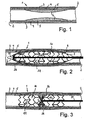
- Fig. 1 is a schematic longitudinal section through a part of a vessel 1, for example a coronary artery shown.
- the vessel 1 has a vessel wall 2, which is composed of three layers. From radially outside to radially inside, these are called the outer vessel wall layer 3, called tunica externa, the middle vessel wall layer 4, called tunica media, and the inner vessel wall layer 5, called intima intima.
- the vessel 1 shows a stenosis 6 by plaque. It is clear that the construction of the vessel 1 described above represents only an exemplary explanation of such a vessel. Just as well, vessels with a different structure can be included.
- FIG. 2 is a schematic longitudinal section through the constricted vessel 1 with inserted balloon catheter 7 and mounted implant 10, namely a stent 11, shown.
- the implant is designed by way of example only as a stent.
- the invention is not limited to an implant designed as a stent; rather, the invention also encompasses other types of implants.
- the invention also includes medical, in particular dental, instruments whose surfaces are at least partially constructed in the manner according to the invention.
- the invention relates generally to implants and medical instruments.
- stent 11 is partially inflated, ie deployed, shown.
- FIG. 3 shows Fig. 3 a schematic, partial longitudinal section through the vessel 1 with now fully inflated stent and distant balloon catheter. 7
- the implant 10 is preferably but not exclusively designed as a stent 11.
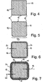
- a stent 11 has numerous webs 12, also called support webs (struts), one of which in each case in cross-section in the Fig. 4 to 7 is shown.
- struts support webs
- FIG. 4 is a cross section through such a web of the stent 11 schematically shown.
- the ridge is, for example surgical steel such as surgical stainless steel 316L, or nitinol ®, a corrosion-resistant and vibration-resistant, steel-hard titanium-nickel alloy manufactured.
- the base material 13 of the stent 11 may also consist of other metals, alloys, non-metals and plastics.
- the in Fig. 4 shown cross section through a web 12 results, for example, after laser cutting of the material from a pipe jacket.
- edges 14 of the base material 13 of the web 12 of the stent 11 are rounded, as will be discussed in more detail later.
- the implant 10 that is, for example, the stent 11, a surface 15 which is coated with a thin layer 16 of titanium (Ti) and titanium dioxide (TiO 2 ), wherein the thin layer 16 from a on the surface 15 of the base material 13 of the implant 10 applied intermediate layer 20 of titanium (Ti) as a connection between the base material 13 of the implant 10 and the surface layer 17 and an outer surface layer 17 of the Ti-O 2 -Mineral anatase consists.
- This surface layer 17 is formed by photo-excitation photocatalytically acting.
- the invention relates to a photoactivatable thin-film surface of the TiO 2 mineral anatase in the form of a monocrystalline layer as the bioactive surface of an implant and / or a medical instrument.
- the two illustrated layers 17, 20 of the thin film 16 are applied to the rounded base material 13 of the implant 10. It follows that, prior to the application of the thin layer 16, first the edges 14 or the corners of the base material are rounded off in an upstream processing step.
- the intermediate layer of titanium may be omitted if the base material of the implant or of the medical instrument is made of titanium or at least contains titanium to a significant extent.
- the thickness 21 of the intermediate layer 20 is 200 to 1000 nm, and preferably, the thickness 22 of the outer surface layer 17 is 100 to 1000 nm.
- the intermediate layer and the outer surface layer 20, 17 are each an all-round coating, preferably an all-sided plasma coating of the implant 10.
- the thin layer 16 as a closed layer 17, 20 on the entire surface 15 of the deflated Implant 10, preferably of the stent 11, applied.
- the edge length 23 of the base material 13 is preferably 0.1 mm. It is clear that the surface 15, unlike in the Fig. 4 to 7 shown, can also be curved.
- the outer surface layer 17 is preferably photodynamically activated or reactivatable by illumination with blue light or UVA light in the wavelength range between 360 and 460 nm.
- activation or reactivation of the outer surface layer 17 may according to the in the FIGS. 2 and 3 shown embodiment of the invention by means of an optical fiber 24.
- the optical fiber 24 has a light 26 in the radial direction radiating fiber optic 25.
- the fiber optic 25 is formed such that the light 26, the optical fiber 24 leaves approximately in the radial direction.
- the reactivation of outer surface layer 17 may preferably be an in vivo reactivation.
- the plasma pretreatment further comprises a plasma surface cleaning and a plasma polishing.
- Fig. 4 shown cross section of a web 12 of the implant 10, the base material 13 in raw form
- the cross section according to Fig. 5 already the aforementioned plasma pretreatment, in particular a rounding of the edges, bumps and the machining burr of the implant base material experienced.
- the layers 20, 17 of titanium and the TiO 2 mineral anatase are applied by a pulsed reactive magnetron sputtering (PMS) process.
- the plasma pretreatment may also include the polishing of the unevenness on the surface 15 of the base material 13.
- the stent 11 is in Fig. 2 in a partially inflated, ie expanded state. As shown, the stent 11 is still mounted on the balloon catheter 7 here.
- the stenosis 6 is already here in comparison to the illustration according to Fig. 1 shown pressed radially outwards, whereby, as in the FIGS. 2 and 3 indicated, a small extension of the vessel 1 may result.
- the vessel 1 according to Fig. 3 is balloon dilated and shown in a state following expansion of stent 11 and balloon catheter 7 removed.
- the stent 11 is thus completely inflated, ie unfolded.
- the optical fiber 24 with its fiber optics 25.
- the activation / reactivation ie the implementation of a photodynamic process, performed on the photoactive outer surface layer 17 by applying light.
- the optical fiber 24 is shown with its fiber optic 25 without the balloon catheter 7.
- the stent is thus able to bring about the constriction caused by a stenosis 6, as in Fig. 1 is indicated to completely eliminate in its inflated state (see illustration according to Fig. 3 ).
- the implant 10 is shown in the form of a stent 11 in a deflated, ie compressed or folded state.
- Fig. 9 has a like in Fig. 8 deflated stent an arc shape, whereas in Fig. 10 a stent 11 is shown in the inflated, ie spread or unfolded state.
- the stent 11 is in the vessel 1 according to Fig. 3 , These illustrations illustrate the easy mobility, such as flexibility, and good flexibility of the implant.
- the implant 10 and the stent 11, respectively may take many different forms and thus may be formed in a variety of embodiments.
- the stents are in the Fig. 8 to 10 merely exemplified.
- the use of light for the in vivo activation or deactivation of implant surfaces can be a contribution to minimally invasive medicine.
- the stent 11 is, for example, an implantable girdle made of wire mesh or metal tubes with recesses in the tube wall for the treatment of closures and constrictions in vessels.
- the reactivation can thus be carried out on photoactivated boundary surfaces of the surface layer of the webs with the intima and the possibly newly formed, growing neointima, in order to prevent the abovementioned restenosis or at least severely limit it.
- Inflation i. the unfolding of the stent may be accomplished by the aforementioned balloon assembly or by self-expansion in vivo.
- the purpose of the intermediate layer 20 of pure titanium is to adapt the expansion coefficients of the base material 13, also called carrier material, to the stent webs and the photoactive outer surface layer of said TiO 2 mineral anatase and to firmly bond the last-mentioned anatase layer to the base material.
- the intermediate layer 20 of pure titanium also has the task of the ablations to be taken during the plastic deformation of the webs of the stent as a result of inflation, ie unfolding, spreading, occurring forces or stresses, such as tensile and compressive stresses, torsional stresses, and to avoid to prevent corrosion of the forming microcracks in the layer and to allow the growth (recrystallization) of new anatase nanocrystallites in the microcracks to anneal the layer surface.
- the mentioned TiO 2 mineral anatase is present in a layer of monocrystallites of the anatase morphology of TiO 2 as a photoactivatable surface.
- the mentioned materials Ti and TiO 2 are hemo- and histocompatible materials and long-term tested as implant materials.
- the implant according to the invention can represent an alternative to medicament-emitting implants, in particular stents, and in a simple and inexpensive variant offer the possibility of avoiding restenosis.
- a method for producing such an implant or medical article is specified.
Landscapes
- Health & Medical Sciences (AREA)
- Chemical & Material Sciences (AREA)
- Inorganic Chemistry (AREA)
- Animal Behavior & Ethology (AREA)
- Surgery (AREA)
- Vascular Medicine (AREA)
- Epidemiology (AREA)
- Life Sciences & Earth Sciences (AREA)
- Heart & Thoracic Surgery (AREA)
- General Health & Medical Sciences (AREA)
- Public Health (AREA)
- Veterinary Medicine (AREA)
- Materials For Medical Uses (AREA)
- Prostheses (AREA)
- Media Introduction/Drainage Providing Device (AREA)
- Physical Vapour Deposition (AREA)
Description
- Die Erfindung bezieht sich auf ein Implantat, insbesondere Stent, dessen Oberfläche mit einer Dünnschicht beschichtet ist, sowie auf ein Verfahren zum Herstellen eines solchen Implantats, insbesondere eines Stents, nach dem Oberbegriff des Patentanspruchs 10.
- Aus der
EP 1 535 660 A1 ist eine Vorrichtung zum Erzeugen wenigstens eines fluiden Reaktionsproduktes aus wenigstens einem fluiden Ausgangsstoff mittels chemischer Reaktion im Plasma dielektrisch behinderter Entladungen bekannt. Diese Vorrichtung hat eine erste Elektrode aus einem porösen, elektrisch leitfähigen Körper, eine zweite Elektrode aus einem ebensolchen Körper und eine zwischen den durchströmbaren Elektroden vorgesehene dielektrische Schicht. Die dielektrische Schicht ist eine Dünnschicht, vorzugsweise eine photokatalytische Dünnschicht aus Titandioxid (TiO2), besonders bevorzugt aus dem TiO2-Mineral Anatas. Jede der genannten Elektroden weist zwischen ihrem porösen Körper und der dielektrischen Schicht dieses Körpers eine vorzugsweise aus Titan (Ti) als Haftvermittler gebildete Übergangsschicht auf. Diese Vorrichtung eignet sich gemäß dem vorgenannten Dokument dazu, im Falle von mit Brennstoffzellen betriebenen Kraftfahrzeugen große Mengen an Wasserstoff aus Kohlenwasserstoffen, insbesondere aus Methan oder Erdgas, Flüssiggasen, vergastem Benzin oder vergastem Diesel, herzustellen, wobei ein solcher Prozess on-board, d.h. unmittelbar im Kraftfahrzeug, erfolgen kann. Die hier beschriebene Vorrichtung eignet sich also zur Herstellung insbesondere von wasserstoffreichem Brenngas für mit Brennstoffzellen ausgerüsteten Kraftfahrzeugen. - Aus der
DE 102 10 465 A1 ist ein photokatalytisches Element zur Aufspaltung von Wasserstoff enthaltenden Verbindungen und ein Verfahren zur Herstellung eines solchen photokatalytischen Elementes bekannt. Bei dem photokatalytischen Element ist eine photokatalytisch wirkende bindemittelfreie Dünnschicht aus einem photohalbleitenden Material auf einem Träger ausgebildet, und der Träger weist eine offenporige Struktur auf oder bildet eine solche offenporige Struktur. Bei dem letztgenannten Verfahren wird auf einem eine offenporige Struktur aufweisenden Träger eine photokatalytisch wirkende bindemittelfreie Dünnschicht mittels eines plasmagestützten Vakuumbeschichtungsverfahrens ausgebildet. Auch in diesem Dokument ist besonderer Bezug genommen auf den Betrieb von Brennstoffzellen. Es ist ferner erwähnt, die genannten photokatalytischen Elemente zur Deodorierung oder Desinfektion beispielsweise von Abluft aus industriellen oder landwirtschaftlichen Prozessen zu nutzen oder zur Reinigung von mit halogenorganischen Verbindungen kontaminiertem Wasser einzusetzen oder die kanzerogenen oder mutagenen Wirkungen derartiger Verbindungen zu beseitigen. Ferner wird gemäß dieser Schrift die photokatalytische Dünnschicht aus Titandioxid der Anatase-Modifikation durch ein reaktives Pulsmagnetronsputtern ausgebildet. Dabei kann eine Zwischenschicht aus hochreinem Titan bestehen, welche beispielsweise mittels eines Sputterprozesses gebildet wird. - Aus der
DE 601 06 962 T2 ist ein poröser, metallischer Stent bekannt, der mit einer keramischen Schicht beschichtet ist und einen pharmakologisch aktiven Wirkstoff aufweist, wobei die Poren des Stents die Fähigkeit haben, pharmakologisch aktive Wirkstoffe aufzunehmen und zu eluieren. Die keramische Schicht kann aus Titandioxid (TiO2) bestehen. Dieses Dokument offenbart ein Verfahren für die Erzeugung einer Polymerbeschichtung oder keramischen Beschichtung des porösen metallischen Stents mit Hilfe von Verfahren der punktuellen Filmablagerung (spotted film deposition) und damit eine deutliche Modifikation der Oberfläche eines metallischen Stents, um die fortgesetzte Abgabe von Medikamenten in unterschiedlicher Intensität aus dem Stent zu ermöglichen.JP 2002 102 330 JP 2005 095584 WO 2005/043166 offenbaren Implantate die beschichtet sind mit Oxiden von Titan und Anatas, und Verfahren zum Herstellen dieser Implantate. - Ferner ist aus der
DE 102 43 132 A1 ein Verfahren zur Herstellung einer biokompatiblen metallionenhaltigen Titanoxid-Beschichtung auf einem Implantat bekannt, wobei die Metallionen unter physiologischen Bedingungen eluierbar und homogen in der Beschichtung verteilt sind. Ferner ist aus dieser Schrift ein Verfahren zum Herstellen eines solchen Implantats bekannt. Unter Titanoxid wird hier im Wesentlichen Titandioxid verstanden. Durch das hier beschriebene Verfahren wird eine Titanoxid-Beschichtung bzw. ein Implantat mit einer Titanoxid-Beschichtung geschaffen, wobei die Metallionen mit antimikrobieller Wirkung unter physiologischen Bedingungen herauslösbar sind. Nach einer gewissen Zeit, wenn die antimikrobiell wirkenden Metallionen im Wesentlichen herausgelöst sind, nimmt die antimikrobielle Wirkung der Beschichtung ab, und das Implantat wird vom Körpergewebe integriert, ist also biokompatibel. - Die sogenannte perkutane transluminale Angioplastie (PTA) von Blutgefäßen, insbesondere von koronaren Arterien, dient dazu, Verengungen oder sogenannte Stenosen zu beseitigen, welche die Blutversorgung beispielsweise menschlicher Organe behindern. Eine übermäßige Neubildung der inneren Gefäßwand, Gefäßintima genannt, innerhalb des Stents gilt als Hauptursache für eine Restenose, also für ein erneutes Verengen des betreffenden Blutgefäßes.
- Der Erfindung liegt die Aufgabe zugrunde, ein Implantat, insbesondere einen Stent, zu schaffen, dessen Verträglichkeit mit Körpergewebe auf besonders einfache Weise verbessert und dadurch eine Restenose verhindert ist. Ferner liegt der Erfindung die Aufgabe zugrunde, ein Verfahren zum Herstellen eines solchen Implantats, insbesondere eines Stents, anzugeben.
- Diese Aufgabe wird durch ein Implantat mit den Merkmalen des Patentanspruchs 1 und durch ein Verfahren mit den Merkmalen des Patentanspruchs 8 gelöst. Vorteilhafte Weiterbildungen sind Gegenstand der jeweiligen Unteransprüche.
- Erfindungsgemäß hat das Implantat, insbesondere der Stent, eine Oberfläche, die mit einer Dünnschicht aus Titan (Ti) und Titandioxid (TiO2) beschichtet ist, wobei die Dünnschicht aus einer auf die Oberfläche des Basismaterials des Implantats aufgebrachten Zwischenschicht aus reinem Titan (Ti) als Verbindung zwischen dem Basismaterial des Implantats und der Oberflächenschicht und einer äußeren Oberflächenschicht aus dem TiO2-Mineral Anatas besteht. Die Oberflächenschicht ist durch Photoanregung photokatalytisch ausgebildet. Ein Implantat mit einer derartigen Dünnschicht weist eine gute Bioverträglichkeit und eine ebenso gute Langzeitverträglichkeit im Zusammenhang mit Körpergewebe auf. Neben verbesserten Gleiteigenschaften und einer ausgezeichneten, sicheren Haftung der Dünnschicht auf metallischen und auch auf nichtmetallischen Basismaterialien des Implantats, auch Trägermaterialien genannt, weist das erfindungsgemäße Implantat eine gute Langzeitakzeptanz und ein gutes Einwachsen im Gewebe, bei Stents in der Gefäßwand, auf. Erfindungsgemäß wird also die verbesserte Verträglichkeit des Implantats nicht wie im vorgenannten Stand der Technik durch pharmakologisch aktive Wirkstoffe oder durch herauslösbare Metallionen mit antimikrobieller Wirkung sondern allein durch den physikalischen Aufbau der Dünnschicht und die sich daraus ergebenden Vorteile erreicht.
- Durch die Photoanregung der äußeren Oberflächenschicht wird diese superhydrophil, wodurch die Gleiteigenschaften verbessert und Anlagerungen, wie z.B. bei einer Thrombose, verhindert werden. Ferner werden durch die Photoanregung der äußeren Oberfläche über photokatalytische Prozesse an der Grenzfläche der photosensiblen Oberflächenschicht und dem Intimagewebe des Gefäßes Substanzen erzeugt, welche die Restenose verhindern oder zurückbilden. Die sogenannte photoaktivierbare Superhydrophilie verbessert ebenfalls die Gleiteigenschaften bei der Angioplastie und verringert das akute Thromboserisiko. Aufgrund der Superhydrophilie werden auch Anlagerungen an dem Implantat-Basismaterial vermieden.
- Die Zwischenschicht aus reinem Titan (Ti) ist eine Art Verbindungsschicht, welche die äußere Oberflächenschicht aus dem TiO2-Mineral Anatas fest mit dem Basismaterial des Implantats verbindet, so dass die äußere Oberflächenschicht eine fixierte oder immobilisierte Oberflächenschicht darstellt. Diese Zwischenschicht aus reinem Titan ist aber nicht nur Verbindungs- und Zwischenschicht sondern wirkt auch als sogenannte Barriereschicht für die Metallionen (sofern vorhanden) des Basismaterials des Implantats. Diese können also nicht nach außen und daher nicht, wie bei dem vorerwähnten Stand der Technik erwähnt, in das Körpergewebe bzw. in die Blutbahn gelangen. Die Zwischenschicht aus Titan weist duktile Eigenschaften auf, wohingegen die äußere Oberflächenschicht aus dem erwähnten TiO2-Mineral keramisch aufgebaut ist und eine monokristalline Struktur hat.
- Gemäß einer anderen bevorzugten Weiterbildung der Erfindung sind die Kanten des Basismaterials des Implantats abgerundet. Dadurch wird die Gefäßinnenwand beim Einsetzen des Stents möglichst wenig gereizt, wodurch das Restenoserisiko geringer gehalten werden kann. Ein erneutes Verengen bzw. Verschließen des Gefäßes ist dadurch weitgehend minimiert. Ein derart ausgestaltetes, erfindungsgemäßes Implantat kann daher besonders schonend an die gewünschte Stelle beispielsweise in einem Blutgefäß eingesetzt werden. Aufgrund der abgerundeten Kanten des Basismaterials werden außerdem die Gleiteigenschaften des Implantats beispielsweise im Blutgefäß verbessert und die Gefahr von Läsionen der Gefäßwand bei einer PTA verringert.
- Vorteilhafterweise beträgt die Dicke der Zwischenschicht 200 bis 1000 nm und vorzugsweise diejenige der äußeren Oberflächenschicht 100 bis 1000 nm. Insofern können die einzelnen Schichten und damit die Dünnschicht insgesamt äußerst dünn gehalten sein.
- Gemäß einer anderen Weiterbildung der Erfindung sind die Zwischenschicht und die äußere Oberflächenschicht jeweils eine allseitige Plasmabeschichtung des Implantats. Daraus folgt, dass das Basismaterial des Implantats, insbesondere des Stents, insgesamt also beispielsweise auch an den innen liegenden Oberflächen des Implantats, oberflächenbeschichtet ist/sind. Dadurch hat das erfindungsgemäße Implantat insgesamt und nicht nur an einzelnen Stellen eine gute Bioverträglichkeit, wodurch das Restenoserisiko deutlich reduziert werden kann.
- Gemäß einer anderen Weiterbildung der Erfindung ist die Dünnschicht als geschlossene Oberflächenschicht auf der gesamten Oberfläche des deflatierten Implantats, vorzugsweise des Stents, aufgebracht. Daraus folgt, dass sich das Implantat bei der Aufbringung der Dünnschicht vorzugsweise im nicht gespreizten oder im nicht entfalteten Zustand befindet.
- Gemäß einer ferner bevorzugten Weiterbildung der Erfindung ist die äußere Oberflächenschicht vorzugsweise durch Beleuchten mit blauem Licht oder UVA-Licht im Wellenlängenbereich zwischen 360 und 460 nm photodynamisch aktivierbar bzw. reaktivierbar, wobei eine Aktivierung bzw. eine In-vivo-Reaktivierung der äußeren Oberflächenschicht mittels einer Lichtleitfaser erfolgen kann, die vorzugsweise eine das Licht in radialer Richtung abstrahlende Faseroptik aufweist. Insofern kann die Photoaktivierung der äußeren Oberflächenschicht unmittelbar vor der Angioplastie durch Photoaktivierung der Hydrophilie mit Hilfe einer einfachen Beleuchtung bzw. Photoanregung der gesamten Implantatoberfläche erfolgen. Es ist ferner möglich, die Hydrophilie bzw. die besonderen Schichteigenschaften zur Nachbehandlung zu einem späteren Zeitpunkt wieder zu reaktivieren, wobei eine derartige Reaktivierung die genannte In-vivo-Reaktivierung sein kann. Dabei können zur Durchführung der photochemischen Prozesse an den Grenzflächen der Innenseite des Implantats, insbesondere des Stents, mit Hilfe von Kathetern in das Implantat, vor allem dem Stent, geschobene Lichtleitfaserkabel und Mikrofaseroptiken zum Einsatz kommen. Insofern kann mit dieser Weiterbildung das Restenoserisiko durch Verhindern der Einwachsprozesse mit Hilfe der genannten Photokatalyse im Rahmen einer In-vivo-Reaktivierung herabgesetzt sein. Die genannte Lichtleitfaser mit ihrer Faseroptik ermöglicht daher ein Bestrahlen des Implantats an dessen Einsatzort, d.h. beispielsweise in einem Blutgefäß wie einem Herzkranzgefäß.
- Das erfindungsgemäße Verfahren zum Herstellen eines Implantats, insbesondere eines Stents, weist folgende Vakuumprozessschritte auf: Plasmavorbehandlung mit Abrundung der Kanten des Implantat-Basismaterials; Sputtern einer Zwischenschicht aus Titan (Ti); Sputtern einer Oberflächenschicht aus dem Titandioxid(TiO2)-Mineral Anatas. Damit kann das Abrunden der Kanten des Implantat-Basismaterials zeitlich vor dem Aufbringen der Dünnschicht auf das Basismaterial erfolgen, so dass das Implantat ausschließlich in abgerundeten Kanten mit der erfindungsgemäßen Dünnschicht versehen wird.
- Vorteilhafterweise umfasst die Plasmavorbehandlung eine Plasmaoberflächenreinigung und eine Plasmapolitur. Damit wird letztlich ausschließlich ein hochreines, gut bioverträgliches Implantat mit der speziellen Dünnschicht bestehend aus zwei Oberflächenschichten versehen.
- Gemäß einer anderen Weiterbildung der Erfindung werden die Zwischenschicht aus Titan und die Oberflächenschicht aus dem TiO2-Mineral Anatas durch einen gepulsten, reaktiven Magnetronsputterprozess (reaktive Pulse Magnetron Sputtering, PMS) aufgebracht. Dieses Aufbringen der beiden Schichten erfolgt also auf die gesamte Aussenfläche des mechanisch fertig bearbeiteten Implantats, wie einen Rohstent. Der Sputterprozess umfasst somit auch die innen liegenden Aussenflächen des Implantats.
- Ausführungsbeispiele des Erfindungsgegenstandes werden nachfolgend anhand der Zeichnung näher erläutert, wobei alle beschriebenen und/oder bildlich dargestellten Merkmale für sich oder in beliebiger Kombination den Gegenstand der vorliegenden Erfindung unabhängig von ihrer Zusammenfassung in den Ansprüchen oder deren Rückbeziehung bilden. Es zeigen:
- Fig. 1
- einen schematischen Längsschnitt durch ein verengtes Gefäß, zum Beispiel ein Herzkranzgefäß;
- Fig. 2
- einen schematischen, teilweisen Längsschnitt durch ein verengtes Gefäß mit eingeführtem Ballonkatheter und montiertem Implantat in Form eines Stents;
- Fig. 3
- einen schematischen, teilweisen Längsschnitt durch ein ballondilatiertes Gefäß nach einer Expansion des Implantats und entferntem Ballonkatheter;
- Fig. 4
- einen schematischen Querschnitt durch einen Steg des Implantats;
- Fig. 5
- einen schematischen Querschnitt durch den Steg nach einer Abrundung der Kanten;
- Fig. 6
- einen schematischen Querschnitt durch den Steg nach Aufbringen einer Zwischenschicht aus Titan auf den Steg gemäß
Fig. 5 ; - Fig. 7
- einen schematischen Querschnitt durch den Steg nach Aufbringen einer Oberflächenschicht aus dem Titandioxid-Mineral Anatas auf den Steg gemäß
Fig. 6 ; - Fig. 8
- eine beispielhafte, schematische Darstellung eines Implantats im deflatierten Zustand;
- Fig. 9
- eine beispielhafte, schematische Darstellung eines Implantats im deflatierten, gebogenen Zustands; und
- Fig. 10
- eine beispielhafte, schematische Darstellung eines Implantats im inflatierten, d.h. gespreizten bzw. entfalteten Zustand.
- In
Fig. 1 ist ein schematischer Längsschnitt durch einen Teil eines Gefäßes 1, z.B. eines Herzkranzgefäßes, gezeigt. Das Gefäß 1 hat eine Gefäßwand 2, welche aus drei Schichten aufgebaut ist. Von radial außen nach radial innen sind dies die äußere Gefäßwandschicht 3, Tunica externa genannt, die mittlere Gefäßwandschicht 4, Tunica media genannt, und die innere Gefäßwandschicht 5, Tunica intima genannt. - Das Gefäß 1 zeigt eine Stenose 6 durch Plaque. Es ist klar, dass der zuvor beschriebene Aufbau des Gefäßes 1 lediglich eine beispielhafte Erläuterung eines solchen Gefäßes darstellt. Ebenso gut können Gefäße mit anderem Aufbau mit umfasst sein.
- In
Fig. 2 ist ein schematischer Längsschnitt durch das verengte Gefäß 1 mit eingeführtem Ballonkatheter 7 und montiertem Implantat 10, nämlich einem Stent 11, dargestellt. - Das Implantat ist lediglich beispielhaft als Stent ausgebildet. Insofern ist die Erfindung nicht auf ein als Stent ausgebildetes Implantat beschränkt; vielmehr umfasst die Erfindung auch andere Arten von Implantaten.
- Die Erfindung umfasst ferner auch medizinische, insbesondere zahnmedizinische Instrumente, deren Oberflächen zumindest teilweise in der erfindungsgemässen Weise aufgebaut sind. Insofern bezieht sich die Erfindung allgemein auf Implantate sowie medizinische Instrumente.
- In
Fig. 2 ist der Stent 11 teilweise inflatiert, d.h. entfaltet, dargestellt. - Demgegenüber zeigt
Fig. 3 einen schematischen, teilweisen Längsschnitt durch das Gefäß 1 mit nunmehr vollständig inflatiertem Stent und entferntem Ballonkatheter 7. - Nachfolgend wird das erfindungsgemäße Implantat 10 mit Bezug auf die
Fig. 4 bis 7 genauer erläutert. - Wie zuvor erwähnt ist das Implantat 10 vorzugsweise aber nicht ausschließlich als Stent 11 ausgebildet. Ein solcher Stent 11 hat zahlreiche Stege 12, auch Stützstege (Struts) genannt, von denen einer jeweils im Querschnitt in den
Fig. 4 bis 7 dargestellt ist. InFig. 4 ist ein Querschnitt durch einen solchen Steg des Stents 11 schematisch dargestellt. Der Steg ist beispielsweise aus chirurgischem Stahl, beispielsweise chirurgischem Stahl 316L, oder aus Nitinol®, einer korrosions- und erschütterungsresistenten, stahlharten Titan-Nickel-Legierung, gefertigt. Das Basismaterial 13 des Stents 11 kann aber auch aus anderen Metallen, Legierungen, auch aus Nichtmetallen und Kunststoffen bestehen. Der inFig. 4 gezeigte Querschnitt durch einen Steg 12 ergibt sich beispielsweise nach Laserausschnitt des Materials aus einem Rohrmantel. - In der Darstellung gemäß
Fig. 5 sind die Kanten 14 des Basismaterials 13 des Stegs 12 des Stents 11 abgerundet, worauf später noch näher eingegangen wird. - Erfindungsgemäß hat das Implantat 10, also beispielsweise der Stent 11, eine Oberfläche 15, die mit einer Dünnschicht 16 aus Titan (Ti) und Titandioxid (TiO2) beschichtet ist, wobei die Dünnschicht 16 aus einer auf die Oberfläche 15 des Basismaterials 13 des Implantats 10 aufgebrachten Zwischenschicht 20 aus Titan (Ti) als Verbindung zwischen dem Basismaterial 13 des Implantats 10 und der Oberflächenschicht 17 und einer äußeren Oberflächenschicht 17 aus den Ti-O2-Mineral Anatas besteht. Diese Oberflächenschicht 17 ist durch Photoanregung photokatalytisch wirkend ausgebildet.
- Die Erfindung betrifft insbesondere eine photoaktivierbare Dünnschichtoberfläche aus dem TiO2-Mineral Anatas in Form einer monokristallinen Schicht als bioaktive Oberfläche eines Implantats und/oder eines medizinischen Instruments.
- Wie zuvor erwähnt, werden die zwei erläuterten Schichten 17, 20 der Dünnschicht 16 auf das abgerundete Basismaterial 13 des Implantats 10 aufgebracht. Daraus folgt, dass vor dem Aufbringen der Dünnschicht 16 zunächst die Kanten 14 bzw. die Ecken des Basismaterials in einem vorgelagerten Bearbeitungsschritt abgerundet werden.
- Es wird darauf hingewiesen, dass die Zwischenschicht aus Titan entfallen kann, sofern das Basismaterial des Implantats bzw. des medizinischen Instruments aus Titan gefertigt ist oder zumindest in nennenswertem Umfang Titan enthält.
- Die Dicke 21 der Zwischenschicht 20 beträgt 200 bis 1000 nm, und vorzugsweise beträgt die Dicke 22 der äußeren Oberflächenschicht 17 100 bis 1000 nm.
- Wie in den
Fig. 4 bis 7 lediglich schematisch angedeutet, sind die Zwischenschicht und die äußere Oberflächenschicht 20, 17 jeweils eine allseitige Beschichtung, vorzugsweise eine allseitige Plasmabeschichtung des Implantats 10. Gemäß einer bevorzugten Ausführungsform der Erfindung ist die Dünnschicht 16 als geschlossene Schicht 17, 20 auf der gesamten Oberfläche 15 des deflatierten Implantats 10, vorzugsweise des Stents 11, aufgebracht. - Die Kantenlänge 23 des Basismaterials 13 beträgt vorzugsweise 0,1 mm. Es ist klar, dass die Oberfläche 15, anders als in den
Fig. 4 bis 7 gezeigt, auch gekrümmt ausgebildet sein kann. - Gemäß einer besonders bevorzugten Ausführungsform der Erfindung ist die äußere Oberflächenschicht 17 vorzugsweise durch Beleuchten mit blauem Licht oder UVA-Licht im Wellenlängenbereich zwischen 360 und 460 nm photodynamisch aktivierbar bzw. reaktivierbar. Eine solche Aktivierung bzw. Reaktivierung der äußeren Oberflächenschicht 17 kann gemäß der in den
Fig. 2 und 3 gezeigten Ausführungsform der Erfindung mittels einer Lichtleitfaser 24 erfolgen. Die Lichtleitfaser 24 hat eine Licht 26 in radialer Richtung abstrahlende Faseroptik 25. Wie in denFig. 2 und 3 angedeutet, ist die Faseroptik 25 derart ausgebildet, dass das Licht 26 die Lichtleitfaser 24 etwa in radialer Richtung verlässt. Wie ferner in denFig. 2 und 3 gezeigt, kann die Reaktivierung der äußeren Oberflächenschicht 17 vorzugsweise eine In-vivo-Reaktivierung sein. - Nachfolgend wird das erfindungsgemäße Verfahren zum Herstellen eines Implantats, insbesondere eines Stents, näher erläutert.
- Das erfindungsgemäße Verfahren weist folgende Vakuumprozessschritte auf:
- Plamavorbehandlung mit Abrundung der Kanten des Implantat-Basismaterials;
- Sputtern einer Zwischenschicht aus reinem Titan (Ti);
- Sputtern einer Oberflächenschicht aus dem Titandioxid(TiO2)-Mineral Anatas.
- Gemäß einer bevorzugten Weiterbildung der Erfindung umfasst die Plasmavorbehandlung ferner eine Plasmaoberflächenreinigung und eine Plasmapolitur.
- Insofern stellt der in
Fig. 4 gezeigte Querschnitt eines Stegs 12 des Implantats 10 das Basismaterial 13 in Rohform dar, wohingegen der Querschnitt gemäßFig. 5 bereits die erwähnte Plasmavorbehandlung, insbesondere eine Abrundung der Kanten, Unebenheiten und des Bearbeitungsgrates des Implantat-Basismaterials, erfahren hat. - Die Schichten 20, 17 aus Titan und dem TiO2-Mineral Anatas werden durch einen gepulsten reaktiven Magnetronsputterprozess (reactive Pulse Magnetron Sputtering, PMS) aufgebracht. Die Plasmavorbehandlung kann auch die Politur bzw. den Ausgleich von Unebenheiten auf der Oberfläche 15 des Basismaterials 13 beinhalten.
- Wie zuvor bereits angedeutet, befindet sich der Stent 11 in
Fig. 2 in einem teilweise inflatierten, d.h. expandierten Zustand. Gemäß dieser Darstellung ist der Stent 11 hier noch auf dem Ballonkatheter 7 montiert. Die Stenose 6 ist hier schon im Vergleich zur Darstellung gemäßFig. 1 radial nach außen gedrückt dargestellt, wodurch, wie in denFig. 2 und 3 angedeutet, sich eine geringe Erweiterung des Gefäßes 1 ergeben kann. - Das Gefäß 1 gemäß
Fig. 3 ist ballondilatiert und in einem Zustand nach einer Expansion des Stents 11 und entferntem Ballonkatheter 7 gezeigt. Der Stent 11 ist somit vollständig inflatiert, d.h. entfaltet. Innerhalb des Ballonkatheters 7 befindet sich gemäßFig. 2 die Lichtleitfaser 24 mit ihrer Faseroptik 25. Mittels Lichtleitfaser und Faseroptik wird die Aktivierung/Reaktivierung, also die Durchführung eines photodynamischen Prozesses, an der photoaktiven äußeren Oberflächenschicht 17 durch Aufbringen von Licht durchgeführt. InFig. 3 ist die Lichtleitfaser 24 mit ihrer Faseroptik 25 ohne den Ballonkatheter 7 gezeigt. Der Stent ist also in der Lage, die durch eine Stenose 6 herbeigeführte Querschnittsverengung, wie sie inFig. 1 angedeutet ist, in seinem inflatierten Zustand vollständig zu beseitigen (siehe Darstellung gemäßFig. 3 ). - In
Fig. 8 ist das Implantat 10 beispielhaft in Form eines Stents 11 in einem deflatierten, d.h. zusammengepressten bzw. -gefalteten Zustand gezeigt. GemäßFig. 9 hat ein wie inFig. 8 deflatierter Stent eine Bogenform, wohingegen inFig. 10 ein Stent 11 im inflatierten, d.h. gespreizten bzw. entfalteten Zustand gezeigt ist. Etwa in dem inFig. 10 gezeigten Zustand befindet sich der Stent 11 in dem Gefäß 1 gemäßFig. 3 . Diese Darstellungen verdeutlichen die leichte Beweglichkeit, wie Biegbarkeit, und gute Flexibilität des Implantats. - Es ist klar, dass das Implantat 10 bzw. der Stent 11 zahlreiche unterschiedliche Formen annehmen und insofern in einer Vielzahl von Ausführungsformen gebildet seinkann. Die Stents sind in den
Fig. 8 bis 10 lediglich beispielhaft dargestellt. - Insofern kann der Einsatz von Licht zur In-vivo-Aktivierung bzw. -Reaktivierung von Implantatoberflächen einen Beitrag zur minimalinvasiven Medizin darstellen. Wie zuvor erwähnt, ist es möglich, das erfindungsgemäße Implantat mit bereits photokatalytisch angeregter äußerer Oberflächenschicht in das Blutgefäß 1 einzusetzen und den Vorgang der erneuten Aktivierung bzw. Reaktivierung der äußeren Oberflächenschicht im eingebauten Zustand des Stents im Blutgefäß ein weiteres Mal durchzuführen.
- Der Stent 11 ist beispielsweise eine implantierbare Gefäßstütze aus Drahtgeflecht oder Metallröhrchen mit Aussparungen in der Rohrwand zur Behandlung von Verschlüssen und Verengungen in Gefäßen. Wie zuvor bereits erwähnt, ist es mittels der Erfindung möglich, die akuten Risiken bei der PTA weiter zu minimieren und insbesondere das Restenoserisiko nach einer PTA zu verringern, wobei dies durch die erwähnte Photoaktivierung bzw. In-vivo-Reaktivierung der photoaktiven Grenzflächen der Oberflächenschicht der Stege erfolgt. Die Reaktivierung kann somit an photoaktivierten Grenzflächen der Oberflächenschicht der Stege mit der Intima und der gegebenenfalls neu gebildeten, wachsenden Neointima durchgeführt werden, um die erwähnte Restenose zu unterbinden oder doch zumindest stark einzuschränken. Die Inflatierung, d.h. die Entfaltung, des Stents kann durch die erwähnte Ballonmontage oder durch Selbstexpansion in vivo erfolgen.
- Die Zwischenschicht 20 aus reinem Titan hat die Aufgabe, die Dehnungskoeffizienten des Basismaterials 13, auch Trägermaterial genannt, der Stentstege und der photoaktiven äußeren Oberflächenschicht aus dem genannten TiO2-Mineral Anatas anzupassen und die letztgenannte Anatas-Schicht fest haftend mit dem Basismaterial zu verbinden. Die Zwischenschicht 20 aus reinem Titan hat ferner die Aufgabe, die bei der plastischen Verformung der Stege des Stents infolge der Inflatation, d.h. Entfaltung, Spreizung, auftretenden Kräfte bzw. Spannungen, wie z.B. Zug-, Druckspannungen, Torsionsspannungen, aufzunehmen, Ablationen zu vermeiden und bei den sich bildenden Mikrorissen in der Schicht Korrosionen zu verhindern sowie das Wachstum (Rekristallisation) von neuen Anatas-Nanokristalliten in den Mikrorissen zur Ausheilung der Schichtoberfläche zu ermöglichen. Das erwähnte TiO2-Mineral Anatas liegt in einer Schicht aus Monokristalliten der Anatas-Morphologie des TiO2 als photoaktivierbare Oberfläche vor.
- Die genannten Materialien Ti sowie TiO2 sind hämo- und histokompatible Werkstoffe und als Implantatmaterialien langzeiterprobt.
- Insofern kann das erfindungsgemäße Implantat eine Alternative zu medikamentenabgebenden Implantaten, insbesondere Stents, darstellen und in einer einfachen und preiswerten Variante die Möglichkeit bieten, eine Restenose zu vermeiden.
- Damit ist ein Implantat bzw. allgemein ein medizinischer Artikel, wie z.B. ein medizinisches Instrument, geschaffen, dessen Verträglichkeit, vor allem Bioverträglichkeit, auf einfache Weise verbessert und das bzw. der in der Lage ist, insbesondere eine Restenose weitgehend zu verhindern. Zusätzlich ist ein Verfahren zum Herstellen eines solchen Implantats bzw. medizinischen Artikels angegeben.
Claims (10)
- Implantat, insbesondere Stent (11),
dessen Oberfläche (15) mit einer Dünnschicht (16) aus Titan (Ti) und Titandioxid (TiO2) beschichtet ist,
wobei die Dünnschicht (16) aus einer auf die Oberfläche (15) des Basismaterials (13) des Implantats (10) aufgebrachten Zwischenschicht (20) aus Titan (Ti) als Verbindung zwischen dem Basismaterial (13) des Implantats (10) und der Oberflächenschicht (17) und einer äußeren Oberflächenschicht (17) aus dem TiO2-Mineral Anatas besteht,
dadurch gekennzeichnet, dass
die Zwischenschicht (20) aus reinem Titan (Ti) gebildet ist und
die Oberflächenschicht (17) durch Photoanregung photokatalytisch wirkend ausgebildet ist. - Implantat nach Anspruch 1, dadurch gekennzeichnet, dass die Kanten (14) des Basismaterials (13) des Implantats (10) abgerundet sind.
- Implantat nach Anspruch 1 oder 2, dadurch gekennzeichnet, dass die Dicke (21) der Zwischenschicht (20) 200 bis 1000 nm und vorzugsweise diejenige (22) der Oberflächenschicht (17) 100 bis 1000 nm beträgt.
- Implantat nach einem der vorhergehenden Ansprüche, dadurch gekennzeichnet, dass die Zwischenschicht (20) und die Oberflächenschicht (17) jeweils eine allseitige Plasmabeschichtung des Implantats (10) sind.
- Implantat nach einem der vorhergehenden Ansprüche, dadurch gekennzeichnet, dass die Dünnschicht (16) als geschlossene Schicht (17, 20) auf der gesamten Oberfläche (15) des Implantats (10), vorzugsweise des Stents (11), aufgebracht ist, wobei das Implantat (10) inflatierbar ausgebildet ist und sich beim Aufbringen der Dünnschicht (16) im deflatierten Zustand befindet.
- Implantat nach einem der vorhergehenden Ansprüche, dadurch gekennzeichnet, dass die Oberflächenschicht (17) vorzugsweise durch Beleuchten mit blauem Licht oder UVA-Licht im Wellenlängenbereich zwischen 360 und 460 nm photodynamisch aktivierbar bzw. reaktivierbar ist.
- Implantat nach Anspruch 6, dadurch gekennzeichnet, dass eine Aktivierung bzw. eine Reaktivierung, vorzugsweise In-vivo-Reaktivierung, der Oberflächenschicht (17) mittels einer Lichtleitfaser (24) erfolgt, die vorzugsweise eine das Licht (26) in radialer Richtung abstrahlende Faseroptik (25) aufweist.
- Verfahren zum Herstellen eines Implantats, insbesondere eines Stents, nach einem der vorhergehenden Ansprüche,
gekennzeichnet durch folgende Vakuumprozessschritte:- Plasmavorbehandlung mit Abrundung der Kanten des Implantat-Basismaterials;- Sputtern einer Zwischenschicht aus reinem Titan (Ti);- Sputtern einer Oberflächenschicht aus dem Titandioxid(TiO2)-Mineral Anatas. - Verfahren nach Anspruch 8, dadurch gekennzeichnet, dass die Plasmavorbehandlung eine Plasmaoberflächenreinigung und eine Plasmapolitur umfasst.
- Verfahren nach Anspruch 8 oder 9, dadurch gekennzeichnet, dass die Schichten aus Titan und dem TiO2-Mineral Anatas durch einen gepulsten, reaktiven Magnetronsputterprozess (reaktive Pulse Magnetron Sputtering, PMS) aufgebracht werden.
Applications Claiming Priority (2)
| Application Number | Priority Date | Filing Date | Title |
|---|---|---|---|
| DE102005053247A DE102005053247A1 (de) | 2005-11-08 | 2005-11-08 | Implantat, insbesondere Stent, und Verfahren zum Herstellen eines solchen Implantats |
| PCT/EP2006/010105 WO2007054192A2 (de) | 2005-11-08 | 2006-10-19 | Implantat, insbesondere stent, und verfahren zum herstellen eines solchen implantats |
Publications (2)
| Publication Number | Publication Date |
|---|---|
| EP1945280A2 EP1945280A2 (de) | 2008-07-23 |
| EP1945280B1 true EP1945280B1 (de) | 2009-12-16 |
Family
ID=37948981
Family Applications (1)
| Application Number | Title | Priority Date | Filing Date |
|---|---|---|---|
| EP06806408A Not-in-force EP1945280B1 (de) | 2005-11-08 | 2006-10-19 | Implantat, insbesondere stent, und verfahren zum herstellen eines solchen implantats |
Country Status (5)
| Country | Link |
|---|---|
| US (1) | US20080262607A1 (de) |
| EP (1) | EP1945280B1 (de) |
| AT (1) | ATE451940T1 (de) |
| DE (2) | DE102005053247A1 (de) |
| WO (1) | WO2007054192A2 (de) |
Families Citing this family (36)
| Publication number | Priority date | Publication date | Assignee | Title |
|---|---|---|---|---|
| US7713297B2 (en) | 1998-04-11 | 2010-05-11 | Boston Scientific Scimed, Inc. | Drug-releasing stent with ceramic-containing layer |
| US20070224235A1 (en) | 2006-03-24 | 2007-09-27 | Barron Tenney | Medical devices having nanoporous coatings for controlled therapeutic agent delivery |
| US8187620B2 (en) | 2006-03-27 | 2012-05-29 | Boston Scientific Scimed, Inc. | Medical devices comprising a porous metal oxide or metal material and a polymer coating for delivering therapeutic agents |
| US8815275B2 (en) | 2006-06-28 | 2014-08-26 | Boston Scientific Scimed, Inc. | Coatings for medical devices comprising a therapeutic agent and a metallic material |
| EP2032091A2 (de) | 2006-06-29 | 2009-03-11 | Boston Scientific Limited | Medizinprodukte mit selektiver beschichtung |
| JP2010503469A (ja) | 2006-09-14 | 2010-02-04 | ボストン サイエンティフィック リミテッド | 薬物溶出性皮膜を有する医療デバイス |
| US20080294236A1 (en) * | 2007-05-23 | 2008-11-27 | Boston Scientific Scimed, Inc. | Endoprosthesis with Select Ceramic and Polymer Coatings |
| US7981150B2 (en) | 2006-11-09 | 2011-07-19 | Boston Scientific Scimed, Inc. | Endoprosthesis with coatings |
| US8431149B2 (en) | 2007-03-01 | 2013-04-30 | Boston Scientific Scimed, Inc. | Coated medical devices for abluminal drug delivery |
| US8070797B2 (en) | 2007-03-01 | 2011-12-06 | Boston Scientific Scimed, Inc. | Medical device with a porous surface for delivery of a therapeutic agent |
| US8067054B2 (en) | 2007-04-05 | 2011-11-29 | Boston Scientific Scimed, Inc. | Stents with ceramic drug reservoir layer and methods of making and using the same |
| US7976915B2 (en) | 2007-05-23 | 2011-07-12 | Boston Scientific Scimed, Inc. | Endoprosthesis with select ceramic morphology |
| US8002823B2 (en) | 2007-07-11 | 2011-08-23 | Boston Scientific Scimed, Inc. | Endoprosthesis coating |
| US7942926B2 (en) | 2007-07-11 | 2011-05-17 | Boston Scientific Scimed, Inc. | Endoprosthesis coating |
| US9284409B2 (en) | 2007-07-19 | 2016-03-15 | Boston Scientific Scimed, Inc. | Endoprosthesis having a non-fouling surface |
| US20090157172A1 (en) * | 2007-07-24 | 2009-06-18 | Boston Scientific Scrimed, Inc. | Stents with polymer-free coatings for delivering a therapeutic agent |
| US7931683B2 (en) | 2007-07-27 | 2011-04-26 | Boston Scientific Scimed, Inc. | Articles having ceramic coated surfaces |
| US8815273B2 (en) | 2007-07-27 | 2014-08-26 | Boston Scientific Scimed, Inc. | Drug eluting medical devices having porous layers |
| WO2009018340A2 (en) | 2007-07-31 | 2009-02-05 | Boston Scientific Scimed, Inc. | Medical device coating by laser cladding |
| JP2010535541A (ja) | 2007-08-03 | 2010-11-25 | ボストン サイエンティフィック リミテッド | 広い表面積を有する医療器具用のコーティング |
| DE102008028308A1 (de) * | 2007-10-18 | 2009-04-23 | Acandis Gmbh & Co. Kg | Vaskuläres Implantat und Verfahren zum Herstellen eines derartigen Implantats |
| US8029554B2 (en) | 2007-11-02 | 2011-10-04 | Boston Scientific Scimed, Inc. | Stent with embedded material |
| US8216632B2 (en) | 2007-11-02 | 2012-07-10 | Boston Scientific Scimed, Inc. | Endoprosthesis coating |
| US7938855B2 (en) | 2007-11-02 | 2011-05-10 | Boston Scientific Scimed, Inc. | Deformable underlayer for stent |
| JP5581311B2 (ja) | 2008-04-22 | 2014-08-27 | ボストン サイエンティフィック サイムド,インコーポレイテッド | 無機材料のコーティングを有する医療デバイス及びその製造方法 |
| WO2009132176A2 (en) | 2008-04-24 | 2009-10-29 | Boston Scientific Scimed, Inc. | Medical devices having inorganic particle layers |
| WO2009155328A2 (en) | 2008-06-18 | 2009-12-23 | Boston Scientific Scimed, Inc. | Endoprosthesis coating |
| US8231980B2 (en) | 2008-12-03 | 2012-07-31 | Boston Scientific Scimed, Inc. | Medical implants including iridium oxide |
| US8071156B2 (en) * | 2009-03-04 | 2011-12-06 | Boston Scientific Scimed, Inc. | Endoprostheses |
| US8287937B2 (en) | 2009-04-24 | 2012-10-16 | Boston Scientific Scimed, Inc. | Endoprosthese |
| KR101223977B1 (ko) | 2010-05-26 | 2013-01-18 | 경상대학교산학협력단 | 독성을 억제하는 타이타늄 나노 구조 스텐트의 제작방법 |
| DE102011083054A1 (de) | 2011-09-20 | 2013-03-21 | Hamburg Innovation Gmbh | Verfahren zur photokatalytisch aktiven Beschichtung von Oberflächen |
| DE102013102746B4 (de) * | 2013-03-18 | 2019-11-21 | Medicon Eg Chirurgiemechaniker-Genossenschaft | Verfahren zur Beschichtung von chirurgischen und medizinischen Instrumenten und beschichtete Instrumente |
| US9918857B2 (en) | 2015-01-14 | 2018-03-20 | Abbott Cardiovascular Systems Inc. | Scaffold having a shaped strut and methods for shaping scaffold struts |
| DE102017111784A1 (de) * | 2017-05-30 | 2018-12-06 | Fraunhofer-Gesellschaft zur Förderung der angewandten Forschung e.V. | Beschichtetes Substrat mit titanhaltiger Beschichtung und modifizierter Titanoxidbeschichtung |
| CN113230004B (zh) * | 2021-04-01 | 2023-07-28 | 上海交通大学医学院附属新华医院 | 一种可吸收血管支架及其制备方法 |
Family Cites Families (5)
| Publication number | Priority date | Publication date | Assignee | Title |
|---|---|---|---|---|
| JP3877505B2 (ja) * | 2000-07-27 | 2007-02-07 | 財団法人イオン工学振興財団 | 生体インプラント材料の製造方法 |
| JP4635177B2 (ja) * | 2003-09-02 | 2011-02-16 | 独立行政法人産業技術総合研究所 | 生体親和性インプラント材及びその製造方法 |
| US20060004317A1 (en) * | 2004-06-30 | 2006-01-05 | Christophe Mauge | Hydrocephalus shunt |
| ITBO20040653A1 (it) * | 2004-10-22 | 2005-01-22 | Guya Bioscience S R L | Metodo per la preparazione d'impianti endossei con elevata osteointegrazione tramite film sottili superficiali di anatasio |
| DE102004052169A1 (de) * | 2004-10-27 | 2006-05-04 | Fraunhofer-Gesellschaft zur Förderung der angewandten Forschung e.V. | Oberflächenveredeltes Objekt, Verfahren zu dessen Herstellung sowie Verwendung des Objektes |
-
2005
- 2005-11-08 DE DE102005053247A patent/DE102005053247A1/de not_active Withdrawn
-
2006
- 2006-10-19 EP EP06806408A patent/EP1945280B1/de not_active Not-in-force
- 2006-10-19 WO PCT/EP2006/010105 patent/WO2007054192A2/de not_active Ceased
- 2006-10-19 US US12/092,913 patent/US20080262607A1/en not_active Abandoned
- 2006-10-19 AT AT06806408T patent/ATE451940T1/de active
- 2006-10-19 DE DE502006005691T patent/DE502006005691D1/de active Active
Also Published As
| Publication number | Publication date |
|---|---|
| DE102005053247A1 (de) | 2007-05-16 |
| US20080262607A1 (en) | 2008-10-23 |
| WO2007054192A3 (de) | 2008-03-27 |
| ATE451940T1 (de) | 2010-01-15 |
| DE502006005691D1 (de) | 2010-01-28 |
| WO2007054192A2 (de) | 2007-05-18 |
| EP1945280A2 (de) | 2008-07-23 |
Similar Documents
| Publication | Publication Date | Title |
|---|---|---|
| EP1945280A2 (de) | Implantat, insbesondere stent, und verfahren zum herstellen eines solchen implantats | |
| DE10145714B4 (de) | Stent | |
| DE602004010895T2 (de) | Abnehmbare und rückholbare stentanordnung | |
| DE69719161T2 (de) | Produktionsverfahren für Stents für Angioplastik | |
| EP0923389B1 (de) | In vivo abbaubares metallisches implantat | |
| DE60316720T2 (de) | Stent mit intermittierender beschichtung | |
| EP0966979B1 (de) | Implantierbare, bioresorbierbare Gefässwandstütze, insbesondere Koronarstent | |
| DE602004011418T2 (de) | Vorrichtung zum Einbringen beschichteter medizinischer Implantate | |
| DE60226236T2 (de) | Mit einer rauhen Oberfläche versehener Stent und sein Herstellungsverfahren | |
| EP2018882B1 (de) | Endoprothese und Verfahren zur Herstellung derselben | |
| DE69736343T2 (de) | Vaskuläre und endoluminale Stents | |
| DE19916315A1 (de) | Verfahren zum Bilden einer dünnen keramikartigen Schicht auf einem Bioimplantat | |
| DE10311729A1 (de) | Endovaskuläres Implantat mit einer mindestens abschnittsweisen aktiven Beschichtung aus Ratjadon und/oder einem Ratjadon-Derivat | |
| DE60114406T2 (de) | Wirkstoffabgabesysteme zur behandlung von gefässerkrankungen | |
| DE102004043232A1 (de) | Endoprothese aus einer Magnesiumlegierung | |
| EP2402044B1 (de) | Implantat und Verfahren zur Herstellung desselben | |
| DE10237572A1 (de) | Stent mit polymerer Beschichtung | |
| EP1932497A1 (de) | Stent zur platzierung im lebenden körper | |
| EP1984033B1 (de) | Verfahren zur umhüllung eines stents | |
| DE602004011897T2 (de) | Stent-Transplantat mit Elutionsöffnungen | |
| WO2006029617A1 (de) | Stützprothese | |
| AU2014236249A1 (en) | Monolithic medical device, methods of making and using the same | |
| EP3068452A1 (de) | Implantat mit erhöhter negativer oberflächenladung | |
| EP1951169A1 (de) | Temporär in einem körperhohlgefäss ablegbarer stent | |
| DE20320682U1 (de) | Medizinisches Implantat, vorzugsweise einen Stent |
Legal Events
| Date | Code | Title | Description |
|---|---|---|---|
| PUAI | Public reference made under article 153(3) epc to a published international application that has entered the european phase |
Free format text: ORIGINAL CODE: 0009012 |
|
| 17P | Request for examination filed |
Effective date: 20080327 |
|
| AK | Designated contracting states |
Kind code of ref document: A2 Designated state(s): AT BE BG CH CY CZ DE DK EE ES FI FR GB GR HU IE IS IT LI LT LU LV MC NL PL PT RO SE SI SK TR |
|
| AX | Request for extension of the european patent |
Extension state: AL BA HR MK RS |
|
| DAX | Request for extension of the european patent (deleted) | ||
| 17Q | First examination report despatched |
Effective date: 20080917 |
|
| GRAP | Despatch of communication of intention to grant a patent |
Free format text: ORIGINAL CODE: EPIDOSNIGR1 |
|
| GRAS | Grant fee paid |
Free format text: ORIGINAL CODE: EPIDOSNIGR3 |
|
| GRAA | (expected) grant |
Free format text: ORIGINAL CODE: 0009210 |
|
| AK | Designated contracting states |
Kind code of ref document: B1 Designated state(s): AT BE BG CH CY CZ DE DK EE ES FI FR GB GR HU IE IS IT LI LT LU LV MC NL PL PT RO SE SI SK TR |
|
| REG | Reference to a national code |
Ref country code: GB Ref legal event code: FG4D Free format text: NOT ENGLISH |
|
| REG | Reference to a national code |
Ref country code: CH Ref legal event code: EP |
|
| REG | Reference to a national code |
Ref country code: IE Ref legal event code: FG4D |
|
| REF | Corresponds to: |
Ref document number: 502006005691 Country of ref document: DE Date of ref document: 20100128 Kind code of ref document: P |
|
| REG | Reference to a national code |
Ref country code: NL Ref legal event code: VDEP Effective date: 20091216 |
|
| PG25 | Lapsed in a contracting state [announced via postgrant information from national office to epo] |
Ref country code: FI Free format text: LAPSE BECAUSE OF FAILURE TO SUBMIT A TRANSLATION OF THE DESCRIPTION OR TO PAY THE FEE WITHIN THE PRESCRIBED TIME-LIMIT Effective date: 20091216 Ref country code: LT Free format text: LAPSE BECAUSE OF FAILURE TO SUBMIT A TRANSLATION OF THE DESCRIPTION OR TO PAY THE FEE WITHIN THE PRESCRIBED TIME-LIMIT Effective date: 20091216 Ref country code: SE Free format text: LAPSE BECAUSE OF FAILURE TO SUBMIT A TRANSLATION OF THE DESCRIPTION OR TO PAY THE FEE WITHIN THE PRESCRIBED TIME-LIMIT Effective date: 20091216 |
|
| LTIE | Lt: invalidation of european patent or patent extension |
Effective date: 20091216 |
|
| PG25 | Lapsed in a contracting state [announced via postgrant information from national office to epo] |
Ref country code: SI Free format text: LAPSE BECAUSE OF FAILURE TO SUBMIT A TRANSLATION OF THE DESCRIPTION OR TO PAY THE FEE WITHIN THE PRESCRIBED TIME-LIMIT Effective date: 20091216 Ref country code: LV Free format text: LAPSE BECAUSE OF FAILURE TO SUBMIT A TRANSLATION OF THE DESCRIPTION OR TO PAY THE FEE WITHIN THE PRESCRIBED TIME-LIMIT Effective date: 20091216 Ref country code: PL Free format text: LAPSE BECAUSE OF FAILURE TO SUBMIT A TRANSLATION OF THE DESCRIPTION OR TO PAY THE FEE WITHIN THE PRESCRIBED TIME-LIMIT Effective date: 20091216 |
|
| REG | Reference to a national code |
Ref country code: IE Ref legal event code: FD4D |
|
| PG25 | Lapsed in a contracting state [announced via postgrant information from national office to epo] |
Ref country code: ES Free format text: LAPSE BECAUSE OF FAILURE TO SUBMIT A TRANSLATION OF THE DESCRIPTION OR TO PAY THE FEE WITHIN THE PRESCRIBED TIME-LIMIT Effective date: 20100327 Ref country code: PT Free format text: LAPSE BECAUSE OF FAILURE TO SUBMIT A TRANSLATION OF THE DESCRIPTION OR TO PAY THE FEE WITHIN THE PRESCRIBED TIME-LIMIT Effective date: 20100416 Ref country code: RO Free format text: LAPSE BECAUSE OF FAILURE TO SUBMIT A TRANSLATION OF THE DESCRIPTION OR TO PAY THE FEE WITHIN THE PRESCRIBED TIME-LIMIT Effective date: 20091216 Ref country code: IE Free format text: LAPSE BECAUSE OF FAILURE TO SUBMIT A TRANSLATION OF THE DESCRIPTION OR TO PAY THE FEE WITHIN THE PRESCRIBED TIME-LIMIT Effective date: 20091216 Ref country code: IS Free format text: LAPSE BECAUSE OF FAILURE TO SUBMIT A TRANSLATION OF THE DESCRIPTION OR TO PAY THE FEE WITHIN THE PRESCRIBED TIME-LIMIT Effective date: 20100416 Ref country code: BG Free format text: LAPSE BECAUSE OF FAILURE TO SUBMIT A TRANSLATION OF THE DESCRIPTION OR TO PAY THE FEE WITHIN THE PRESCRIBED TIME-LIMIT Effective date: 20100316 Ref country code: NL Free format text: LAPSE BECAUSE OF FAILURE TO SUBMIT A TRANSLATION OF THE DESCRIPTION OR TO PAY THE FEE WITHIN THE PRESCRIBED TIME-LIMIT Effective date: 20091216 Ref country code: EE Free format text: LAPSE BECAUSE OF FAILURE TO SUBMIT A TRANSLATION OF THE DESCRIPTION OR TO PAY THE FEE WITHIN THE PRESCRIBED TIME-LIMIT Effective date: 20091216 |
|
| PG25 | Lapsed in a contracting state [announced via postgrant information from national office to epo] |
Ref country code: SK Free format text: LAPSE BECAUSE OF FAILURE TO SUBMIT A TRANSLATION OF THE DESCRIPTION OR TO PAY THE FEE WITHIN THE PRESCRIBED TIME-LIMIT Effective date: 20091216 Ref country code: CZ Free format text: LAPSE BECAUSE OF FAILURE TO SUBMIT A TRANSLATION OF THE DESCRIPTION OR TO PAY THE FEE WITHIN THE PRESCRIBED TIME-LIMIT Effective date: 20091216 |
|
| PLBE | No opposition filed within time limit |
Free format text: ORIGINAL CODE: 0009261 |
|
| STAA | Information on the status of an ep patent application or granted ep patent |
Free format text: STATUS: NO OPPOSITION FILED WITHIN TIME LIMIT |
|
| PG25 | Lapsed in a contracting state [announced via postgrant information from national office to epo] |
Ref country code: CY Free format text: LAPSE BECAUSE OF FAILURE TO SUBMIT A TRANSLATION OF THE DESCRIPTION OR TO PAY THE FEE WITHIN THE PRESCRIBED TIME-LIMIT Effective date: 20091216 Ref country code: GR Free format text: LAPSE BECAUSE OF FAILURE TO SUBMIT A TRANSLATION OF THE DESCRIPTION OR TO PAY THE FEE WITHIN THE PRESCRIBED TIME-LIMIT Effective date: 20100317 |
|
| 26N | No opposition filed |
Effective date: 20100917 |
|
| PG25 | Lapsed in a contracting state [announced via postgrant information from national office to epo] |
Ref country code: DK Free format text: LAPSE BECAUSE OF FAILURE TO SUBMIT A TRANSLATION OF THE DESCRIPTION OR TO PAY THE FEE WITHIN THE PRESCRIBED TIME-LIMIT Effective date: 20091216 |
|
| PG25 | Lapsed in a contracting state [announced via postgrant information from national office to epo] |
Ref country code: IT Free format text: LAPSE BECAUSE OF FAILURE TO SUBMIT A TRANSLATION OF THE DESCRIPTION OR TO PAY THE FEE WITHIN THE PRESCRIBED TIME-LIMIT Effective date: 20091216 |
|
| BERE | Be: lapsed |
Owner name: FRICKE, MARTIN Effective date: 20101031 |
|
| PG25 | Lapsed in a contracting state [announced via postgrant information from national office to epo] |
Ref country code: MC Free format text: LAPSE BECAUSE OF NON-PAYMENT OF DUE FEES Effective date: 20101031 |
|
| REG | Reference to a national code |
Ref country code: CH Ref legal event code: PL |
|
| GBPC | Gb: european patent ceased through non-payment of renewal fee |
Effective date: 20101019 |
|
| PG25 | Lapsed in a contracting state [announced via postgrant information from national office to epo] |
Ref country code: FR Free format text: LAPSE BECAUSE OF NON-PAYMENT OF DUE FEES Effective date: 20101102 Ref country code: LI Free format text: LAPSE BECAUSE OF NON-PAYMENT OF DUE FEES Effective date: 20101031 Ref country code: CH Free format text: LAPSE BECAUSE OF NON-PAYMENT OF DUE FEES Effective date: 20101031 |
|
| REG | Reference to a national code |
Ref country code: FR Ref legal event code: ST Effective date: 20110630 |
|
| PG25 | Lapsed in a contracting state [announced via postgrant information from national office to epo] |
Ref country code: GB Free format text: LAPSE BECAUSE OF NON-PAYMENT OF DUE FEES Effective date: 20101019 Ref country code: BE Free format text: LAPSE BECAUSE OF NON-PAYMENT OF DUE FEES Effective date: 20101031 |
|
| PG25 | Lapsed in a contracting state [announced via postgrant information from national office to epo] |
Ref country code: LU Free format text: LAPSE BECAUSE OF NON-PAYMENT OF DUE FEES Effective date: 20101019 Ref country code: HU Free format text: LAPSE BECAUSE OF FAILURE TO SUBMIT A TRANSLATION OF THE DESCRIPTION OR TO PAY THE FEE WITHIN THE PRESCRIBED TIME-LIMIT Effective date: 20100617 |
|
| PG25 | Lapsed in a contracting state [announced via postgrant information from national office to epo] |
Ref country code: TR Free format text: LAPSE BECAUSE OF FAILURE TO SUBMIT A TRANSLATION OF THE DESCRIPTION OR TO PAY THE FEE WITHIN THE PRESCRIBED TIME-LIMIT Effective date: 20091216 |
|
| REG | Reference to a national code |
Ref country code: AT Ref legal event code: MM01 Ref document number: 451940 Country of ref document: AT Kind code of ref document: T Effective date: 20111019 |
|
| PG25 | Lapsed in a contracting state [announced via postgrant information from national office to epo] |
Ref country code: AT Free format text: LAPSE BECAUSE OF NON-PAYMENT OF DUE FEES Effective date: 20111019 |
|
| PGFP | Annual fee paid to national office [announced via postgrant information from national office to epo] |
Ref country code: DE Payment date: 20151222 Year of fee payment: 10 |
|
| REG | Reference to a national code |
Ref country code: DE Ref legal event code: R119 Ref document number: 502006005691 Country of ref document: DE |
|
| PG25 | Lapsed in a contracting state [announced via postgrant information from national office to epo] |
Ref country code: DE Free format text: LAPSE BECAUSE OF NON-PAYMENT OF DUE FEES Effective date: 20170503 |