EP1945931B1 - Dispositif permettant le deplacement axial d'un rotor de turbine - Google Patents
Dispositif permettant le deplacement axial d'un rotor de turbine Download PDFInfo
- Publication number
- EP1945931B1 EP1945931B1 EP06805383.4A EP06805383A EP1945931B1 EP 1945931 B1 EP1945931 B1 EP 1945931B1 EP 06805383 A EP06805383 A EP 06805383A EP 1945931 B1 EP1945931 B1 EP 1945931B1
- Authority
- EP
- European Patent Office
- Prior art keywords
- turbine
- shaft
- turbine rotor
- axial
- axial displacement
- Prior art date
- Legal status (The legal status is an assumption and is not a legal conclusion. Google has not performed a legal analysis and makes no representation as to the accuracy of the status listed.)
- Not-in-force
Links
- 238000006073 displacement reaction Methods 0.000 claims description 41
- 230000008878 coupling Effects 0.000 claims description 7
- 238000010168 coupling process Methods 0.000 claims description 7
- 238000005859 coupling reaction Methods 0.000 claims description 7
- 238000010276 construction Methods 0.000 claims description 3
- 230000001105 regulatory effect Effects 0.000 claims 1
- 239000000446 fuel Substances 0.000 description 6
- 238000007789 sealing Methods 0.000 description 4
- 230000001419 dependent effect Effects 0.000 description 2
- 238000010586 diagram Methods 0.000 description 2
- 239000012530 fluid Substances 0.000 description 2
- 238000000034 method Methods 0.000 description 2
- 238000013016 damping Methods 0.000 description 1
- 230000006866 deterioration Effects 0.000 description 1
- 238000011161 development Methods 0.000 description 1
- 230000018109 developmental process Effects 0.000 description 1
- 230000005284 excitation Effects 0.000 description 1
- 238000007667 floating Methods 0.000 description 1
- 230000007774 longterm Effects 0.000 description 1
- 238000010248 power generation Methods 0.000 description 1
- 238000013022 venting Methods 0.000 description 1
Images
Classifications
-
- F—MECHANICAL ENGINEERING; LIGHTING; HEATING; WEAPONS; BLASTING
- F02—COMBUSTION ENGINES; HOT-GAS OR COMBUSTION-PRODUCT ENGINE PLANTS
- F02C—GAS-TURBINE PLANTS; AIR INTAKES FOR JET-PROPULSION PLANTS; CONTROLLING FUEL SUPPLY IN AIR-BREATHING JET-PROPULSION PLANTS
- F02C7/00—Features, components parts, details or accessories, not provided for in, or of interest apart form groups F02C1/00 - F02C6/00; Air intakes for jet-propulsion plants
- F02C7/36—Power transmission arrangements between the different shafts of the gas turbine plant, or between the gas-turbine plant and the power user
-
- F—MECHANICAL ENGINEERING; LIGHTING; HEATING; WEAPONS; BLASTING
- F01—MACHINES OR ENGINES IN GENERAL; ENGINE PLANTS IN GENERAL; STEAM ENGINES
- F01D—NON-POSITIVE DISPLACEMENT MACHINES OR ENGINES, e.g. STEAM TURBINES
- F01D11/00—Preventing or minimising internal leakage of working-fluid, e.g. between stages
- F01D11/08—Preventing or minimising internal leakage of working-fluid, e.g. between stages for sealing space between rotor blade tips and stator
- F01D11/14—Adjusting or regulating tip-clearance, i.e. distance between rotor-blade tips and stator casing
- F01D11/20—Actively adjusting tip-clearance
- F01D11/22—Actively adjusting tip-clearance by mechanically actuating the stator or rotor components, e.g. moving shroud sections relative to the rotor
-
- F—MECHANICAL ENGINEERING; LIGHTING; HEATING; WEAPONS; BLASTING
- F01—MACHINES OR ENGINES IN GENERAL; ENGINE PLANTS IN GENERAL; STEAM ENGINES
- F01D—NON-POSITIVE DISPLACEMENT MACHINES OR ENGINES, e.g. STEAM TURBINES
- F01D3/00—Machines or engines with axial-thrust balancing effected by working-fluid
- F01D3/04—Machines or engines with axial-thrust balancing effected by working-fluid axial thrust being compensated by thrust-balancing dummy piston or the like
-
- F—MECHANICAL ENGINEERING; LIGHTING; HEATING; WEAPONS; BLASTING
- F01—MACHINES OR ENGINES IN GENERAL; ENGINE PLANTS IN GENERAL; STEAM ENGINES
- F01D—NON-POSITIVE DISPLACEMENT MACHINES OR ENGINES, e.g. STEAM TURBINES
- F01D5/00—Blades; Blade-carrying members; Heating, heat-insulating, cooling or antivibration means on the blades or the members
- F01D5/02—Blade-carrying members, e.g. rotors
- F01D5/06—Rotors for more than one axial stage, e.g. of drum or multiple disc type; Details thereof, e.g. shafts, shaft connections
- F01D5/066—Connecting means for joining rotor-discs or rotor-elements together, e.g. by a central bolt, by clamps
-
- F—MECHANICAL ENGINEERING; LIGHTING; HEATING; WEAPONS; BLASTING
- F16—ENGINEERING ELEMENTS AND UNITS; GENERAL MEASURES FOR PRODUCING AND MAINTAINING EFFECTIVE FUNCTIONING OF MACHINES OR INSTALLATIONS; THERMAL INSULATION IN GENERAL
- F16D—COUPLINGS FOR TRANSMITTING ROTATION; CLUTCHES; BRAKES
- F16D3/00—Yielding couplings, i.e. with means permitting movement between the connected parts during the drive
- F16D3/02—Yielding couplings, i.e. with means permitting movement between the connected parts during the drive adapted to specific functions
- F16D3/06—Yielding couplings, i.e. with means permitting movement between the connected parts during the drive adapted to specific functions specially adapted to allow axial displacement
-
- F—MECHANICAL ENGINEERING; LIGHTING; HEATING; WEAPONS; BLASTING
- F05—INDEXING SCHEMES RELATING TO ENGINES OR PUMPS IN VARIOUS SUBCLASSES OF CLASSES F01-F04
- F05D—INDEXING SCHEME FOR ASPECTS RELATING TO NON-POSITIVE-DISPLACEMENT MACHINES OR ENGINES, GAS-TURBINES OR JET-PROPULSION PLANTS
- F05D2260/00—Function
- F05D2260/40—Transmission of power
- F05D2260/407—Transmission of power through piezoelectric conversion
-
- Y—GENERAL TAGGING OF NEW TECHNOLOGICAL DEVELOPMENTS; GENERAL TAGGING OF CROSS-SECTIONAL TECHNOLOGIES SPANNING OVER SEVERAL SECTIONS OF THE IPC; TECHNICAL SUBJECTS COVERED BY FORMER USPC CROSS-REFERENCE ART COLLECTIONS [XRACs] AND DIGESTS
- Y02—TECHNOLOGIES OR APPLICATIONS FOR MITIGATION OR ADAPTATION AGAINST CLIMATE CHANGE
- Y02T—CLIMATE CHANGE MITIGATION TECHNOLOGIES RELATED TO TRANSPORTATION
- Y02T50/00—Aeronautics or air transport
- Y02T50/60—Efficient propulsion technologies, e.g. for aircraft
Definitions
- the invention relates to a device for the active axial displacement of at least one turbine rotor connected to a turbine shaft relative to at least one corresponding turbine stator in a multi-stage axial turbine.
- the efficiency of a multi-stage axial turbine depends on the axial arrangement of the rotor blades relative to the stator blades.
- “Clocking” in turbine stators and turbine rotors means that the respective number of vanes of stator or rotor in the lattices are the same, and the lattice to lattice circumferential position is theoretically and experimentally chosen to give optimum turbine efficiency. This turbine efficiency optimum, in turn, also depends on the axial position of the turbine rotor to the turbine stator.
- the document US Pat. No. 1,823,310 A1 relates to a device for the active axial displacement of a turbine rotor connected to a turbine shaft relative to a corresponding turbine stator for the purpose of a load-dependent gap adjustment, preferably at the blade tips.
- the entire turbine shaft is axially moved by means of an axially adjustable thrust bearing (thrust bearing).
- turbine noise and the excitation of turbine blade vibrations can be affected by unwanted axial displacement of the turbine rotor relative to the stator.
- the invention is therefore based on the object to avoid the above-mentioned technical problems of the prior art and to provide an adjustment for the distance of the turbine rotor relative to the turbine stator at standstill and / or during operation.
- the device according to the invention for the active axial displacement of at least one turbine rotor connected to a turbine shaft relative to at least one corresponding turbine stator in a multi-stage axial turbine has a split turbine shaft with a first axially displaceable shaft half, which is connected via a turbine disk to the turbine rotor and via an axially adjustable torque-axial force coupling with a second axially fixed shaft half torque transmitting.
- Such optimized turbine stages can be used in all multi-stage air, gas or steam flow stationary drives for power generation, in marine propulsion, in land or aircraft propulsion.
- An advantageous embodiment of the invention provides that the device has a sliding piece for axially sliding over the two shaft halves. Since the length of the sliding piece limits the displacement, it is first of all sensible to calculate the maximum displacement.
- an advantageous embodiment of the invention provides that the device has a toothing as a torque coupling.
- other positive couplings can be used here come as long as they allow an axial displacement of the two shaft halves relative to each other.
- the device has an adjustment chamber.
- the adjustment chamber can be, for example, a circumferential receptacle for the superimposed axially sliding toothed shaft halves of the hollow turbine shaft, in which a corresponding actuating mechanism for the axial displacement is arranged.
- an advantageous embodiment of the invention provides that the adjustment chamber has a pressure chamber for hydraulic or pneumatic actuation.
- hydraulic fluids come here, for example, oil or fuel used.
- an advantageous embodiment of the invention provides that the device is mechanically, electromagnetically or piezoelectrically actuated.
- a combination of the various operations may be useful, for example, a mechanical actuation with a spring or via lever linkage and an electromagnetic or hydraulic actuation.
- An advantageous embodiment of the invention provides that a displacement of the split turbine shaft of + 4 mm to - 4 mm is provided, for example, for a low-pressure turbine with 77 klbf starting thrust.
- the displacement in the specified order of + 4 mm to - 4 mm is expressed in a parameter that represents the aerodynamic performance of a turbine, that is, their efficiency features, and which is used as a setting and control signal.
- An advantageous embodiment of the invention provides that a device for controlling the displacement of the split turbine shaft is provided.
- An advantageous embodiment of the invention provides that sensor devices are provided for detecting the actual position of the turbine shaft.
- sensor devices are provided for detecting the actual position of the turbine shaft.
- characteristic quantities such as low and high pressure shaft speed, engine pressure ratio, shaft power, net thrust, or the like
- the efficiency of the turbine is represented by characteristic quantities and can be adjusted to its optimum by optimizing these quantities.
- characteristics include the ratio of high and low pressure shaft speeds, fuel consumption, thrust specific fuel consumption, fuel power specific fuel consumption, exhaust temperature, turbine inlet temperature, and the like.
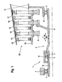
- FIG. 1 shows a schematic example representation of an embodiment of a device 1 for the axial displacement of turbine rotors 13, 15, 17 relative to corresponding Turbinenstatoren 12, 14, 16 in a multi-stage axial turbine 25.
- the axial turbine 25 with sealing rings 10 and turbine disks 9 connected rotor blades and with one Turbine housing 11 connected stator blades on.
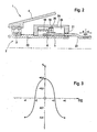
- FIG. 2 shows the displacement device 1 from FIG. 1 in a detailed view.
- a turbine shaft 2 is designed to be split between a fixed bearing 3 arranged in a fixed bearing carrier 4 and a floating bearing 7 arranged in a bearing carrier 8 so that the rear shaft half 23 connected to the movable bearing 7 axially opposite the front shaft half 22 connected to the fixed bearing 3 in a sliding connection 5 is displaceable.
- the displacement device 1 consists of a arranged on the front half shaft 22, rotating over the shaft circumference chamber 24 with a rectangular cross section (see also FIG. 2 ), in which the rear shaft half 23 is received axially displaceable and this is sealed relative to the chamber 24 with sealing rings 21.
- a toothing 6 between the front shaft half 22 and the rear shaft half 23 is provided in the chamber 24.
- the chamber 24 is defined by a circumferential web 18 which is fixedly connected to the rear shaft half 23, e.g. welded, divided into two areas.
- the web 18 is sealed relative to the chamber 24 with sealing rings 26. Further, the gap through which the rear shaft half 23 is guided into the chamber 24, sealed with sealing rings 21.
- a pressure chamber 20 is formed, via which the web 18 is pressurized with hydraulic fluid and can be printed against the springs 19.
- the displacement is in the present embodiment - 4 mm and + 4 mm, calculated from a predefined 0 position.
- the actual position of the rotors 13, 15, 17 compared with the rotor position required for the optimal turbine efficiency and calculated by a (not shown) control device a corresponding travel.
- the displacement mechanism is controlled by the control unit and the two shaft halves 22, 23 against each other.
- the axial displacement and the control of the axial displacement of the turbine rotor relative to the axial position of the fixed Turbinenstators in the range of about 4 mm in both directions thus takes place by axial elongation or reduction of the turbine shaft, one end of which is fixed axially on the fixed bearing.
- the axial elongation or reduction takes place in such a way that the turbine shaft is displaceable axially on the slide neck, the torque being transmitted by the toothing.
- the axial position of the turbine shaft relative to the axially fixed to the fixed bearing slide is determined by a controlled mechanism, which is combined mechanically / hydraulically actuated in the present embodiment.
- the fixed bearing and the sliding bearing function can also be combined.
- FIG. 3 shows a diagram in which the change in the turbine efficiency in percent over the axial rotor displacement relative to the stator in mm is shown. This results in approximately a bell curve, which at - 4 mm and at + 4 mm in each case a minimum with an efficiency change of - 0.4%. At - 2 mm and at + 2 mm, the change in efficiency is 0. At 0 mm rotor displacement relative to the stator, ie at the design point, the change in turbine efficiency reaches an optimum. The change in efficiency here is + 0.4%.
- the invention is not limited in its execution to the above-mentioned preferred embodiment. Rather, a number of variants is conceivable, which makes use of the illustrated solution even with fundamentally different types of use.
Landscapes
- Engineering & Computer Science (AREA)
- General Engineering & Computer Science (AREA)
- Mechanical Engineering (AREA)
- Chemical & Material Sciences (AREA)
- Combustion & Propulsion (AREA)
- Control Of Turbines (AREA)
- Turbine Rotor Nozzle Sealing (AREA)
Claims (11)
- Dispositif servant à déplacer activement par coulissement de manière axiale au moins un rotor de turbine (13, 15, 17) relié à un arbre de turbine (2) par rapport à au moins un stator de turbine (12, 14, 16) correspondant dans une turbine axiale (25) à plusieurs niveaux, caractérisé en ce que l'arbre de turbine (2) est réalisé de manière divisée et présente une première moitié d'arbre (23) pouvant être déplacée par coulissement de manière axiale, laquelle est reliée, de manière à transmettre un couple de rotation, au rotor de turbine (13, 15, 17) par l'intermédiaire d'un disque de turbine (9) et à une deuxième moitié d'arbre (22) fixe de manière axiale par l'intermédiaire d'un couplage de force axiale de couple de rotation (6) pouvant être déplacé de manière axiale.
- Dispositif servant à déplacer par coulissement de manière axiale un rotor de turbine selon la revendication 1, caractérisé en ce que le dispositif présente un support coulissant (5) servant à faire glisser de manière axiale l'une sur l'autre les deux moitiés d'arbre (22, 23).
- Dispositif servant à déplacer par coulissement de manière axiale un rotor de turbine selon l'une quelconque des revendications précédentes, caractérisé en ce que le dispositif présente une denture (6) en tant que couplage de couple de rotation.
- Dispositif servant à déplacer par coulissement de manière axiale un rotor de turbine selon l'une quelconque des revendications précédentes, caractérisé en ce que le dispositif présente une chambre de déplacement (24) servant à absorber la force axiale du rotor de turbine.
- Dispositif servant à déplacer par coulissement de manière axiale un rotor de turbine selon l'une quelconque des revendications précédentes, caractérisé en ce que la chambre de déplacement (24) présente une chambre de pression (20) servant à déplacer par coulissement de manière hydraulique ou pneumatique les deux moitiés d'arbre (22, 23) l'une par rapport à l'autre.
- Dispositif servant à déplacer par coulissement de manière axiale un rotor de turbine selon l'une quelconque des revendications précédentes, caractérisé en ce que le dispositif 1 peut être actionné de manière mécanique.
- Dispositif servant à déplacer par coulissement de manière axiale un rotor de turbine selon l'une quelconque des revendications précédentes, caractérisé en ce que le dispositif 1 peut être actionné de manière électromagnétique.
- Dispositif servant à déplacer par coulissement de manière axiale un rotor de turbine selon l'une quelconque des revendications précédentes, caractérisé en ce que le dispositif 1 peut être actionné de manière piézoélectrique.
- Dispositif servant à déplacer par coulissement de manière axiale un rotor de turbine selon l'une quelconque des revendications précédentes, caractérisé en ce qu'un trajet de déplacement par coulissement caractéristique de l'arbre de turbine (22, 23) divisé de + 4 mm à - 4 mm est prévu.
- Dispositif servant à déplacer par coulissement de manière axiale un rotor de turbine selon l'une quelconque des revendications précédentes, caractérisé en ce qu'un dispositif servant à réguler le trajet de déplacement par coulissement de l'arbre de turbine (22, 23) divisé est prévu.
- Dispositif servant à déplacer par coulissement de manière axiale un rotor de turbine selon l'une quelconque des revendications précédentes, caractérisé en ce que des systèmes de détection sont prévus pour détecter la position réelle de l'arbre de turbine (22, 23) divisé.
Applications Claiming Priority (2)
| Application Number | Priority Date | Filing Date | Title |
|---|---|---|---|
| DE102005048982A DE102005048982A1 (de) | 2005-10-13 | 2005-10-13 | Vorrichtung und Verfahren zum axialen Verschieben eines Turbinenrotors |
| PCT/DE2006/001765 WO2007041997A2 (fr) | 2005-10-13 | 2006-10-10 | Dispositif et procede permettant le deplacement axial d'un rotor de turbine |
Publications (2)
| Publication Number | Publication Date |
|---|---|
| EP1945931A2 EP1945931A2 (fr) | 2008-07-23 |
| EP1945931B1 true EP1945931B1 (fr) | 2013-07-10 |
Family
ID=37836902
Family Applications (1)
| Application Number | Title | Priority Date | Filing Date |
|---|---|---|---|
| EP06805383.4A Not-in-force EP1945931B1 (fr) | 2005-10-13 | 2006-10-10 | Dispositif permettant le deplacement axial d'un rotor de turbine |
Country Status (4)
| Country | Link |
|---|---|
| US (1) | US8449243B2 (fr) |
| EP (1) | EP1945931B1 (fr) |
| DE (1) | DE102005048982A1 (fr) |
| WO (1) | WO2007041997A2 (fr) |
Cited By (1)
| Publication number | Priority date | Publication date | Assignee | Title |
|---|---|---|---|---|
| WO2025082627A1 (fr) * | 2023-10-16 | 2025-04-24 | MPS-Consulting GmbH | Anneau de renforcement de turbine à gaz présentant une pluralité de zones de jeu |
Families Citing this family (27)
| Publication number | Priority date | Publication date | Assignee | Title |
|---|---|---|---|---|
| US7909566B1 (en) * | 2006-04-20 | 2011-03-22 | Florida Turbine Technologies, Inc. | Rotor thrust balance activated tip clearance control system |
| US20100054922A1 (en) * | 2008-09-04 | 2010-03-04 | General Electric Company | Turbine airfoil clocking |
| EP2206889A1 (fr) * | 2009-01-13 | 2010-07-14 | Siemens Aktiengesellschaft | Procédé de réduction de jeu des extrémités des aubes par un rotor déplaçable et turbine à gaz associée |
| EP2239423A1 (fr) * | 2009-03-31 | 2010-10-13 | Siemens Aktiengesellschaft | Turbomachine axiale dotée d'un contrôle passif d'étanchéité en bout d'aube |
| JP5511561B2 (ja) * | 2010-07-14 | 2014-06-04 | 株式会社日立製作所 | 蒸気タービンのシール構造、およびその制御方法 |
| US8864443B2 (en) | 2010-07-14 | 2014-10-21 | Hitachi, Ltd. | Sealing device for steam turbines and method for controlling sealing device |
| EP2415966A1 (fr) * | 2010-08-05 | 2012-02-08 | Siemens Aktiengesellschaft | Train d'entraînement pour turbine à gaz |
| DE102010045851A1 (de) | 2010-09-17 | 2012-03-22 | Mtu Aero Engines Gmbh | Kompensation unterschiedlicher Längsdehnungen von Gehäuse und Rotorwelle einer Turbomaschine |
| DE102011003841A1 (de) * | 2011-02-09 | 2012-08-09 | Siemens Aktiengesellschaft | Turbine mit relativ zueinander einstellbaren Rotor und Turbinengehäuse |
| DE102011100703A1 (de) | 2011-05-05 | 2012-11-08 | Festo Ag & Co. Kg | Strömungsmaschine |
| EP2546459A1 (fr) * | 2011-07-14 | 2013-01-16 | Siemens Aktiengesellschaft | Train de rotor de système de turbines |
| DE102012213016A1 (de) * | 2012-07-25 | 2014-01-30 | Siemens Aktiengesellschaft | Verfahren zur Minimierung des Spalts zwischen einem Läufer und einem Gehäuse |
| FR2995019B1 (fr) * | 2012-09-06 | 2014-09-12 | Snecma | Turbomachine comportant un dispositif de mesure de la distance axiale entre une piece de stator et une piece de rotor de la turbomachine |
| US20160160875A1 (en) * | 2013-08-26 | 2016-06-09 | United Technologies Corporation | Gas turbine engine with fan clearance control |
| US11143051B2 (en) * | 2013-10-02 | 2021-10-12 | Raytheon Technologies Corporation | Translating compressor and turbine rotors for clearance control |
| DE102014203318A1 (de) * | 2014-02-25 | 2015-08-27 | Siemens Aktiengesellschaft | Verfahren zum Betrieb einer Gasturbine bei aktiver hydraulischer Spalteinstellung |
| US9593589B2 (en) * | 2014-02-28 | 2017-03-14 | General Electric Company | System and method for thrust bearing actuation to actively control clearance in a turbo machine |
| US9840932B2 (en) | 2014-10-06 | 2017-12-12 | General Electric Company | System and method for blade tip clearance control |
| CN105089817B (zh) * | 2015-09-18 | 2017-11-21 | 中国航空工业集团公司沈阳发动机设计研究所 | 一种燃气轮机 |
| RU2614905C1 (ru) * | 2016-03-11 | 2017-03-30 | Публичное акционерное общество "Уфимское моторостроительное производственное объединение" ПАО "УМПО" | Компрессор низкого давления газотурбинного двигателя |
| CN105889125B (zh) * | 2016-06-21 | 2019-01-18 | 中国航空工业集团公司沈阳发动机设计研究所 | 一种压气机转子 |
| FR3070419B1 (fr) | 2017-08-25 | 2019-08-23 | Safran Aircraft Engines | Turboreacteur a double corps ayant un palier de butee d'arbre basse pression positionne dans le carter d'echappement |
| FR3081197B1 (fr) * | 2018-05-15 | 2021-12-10 | Safran Aircraft Engines | Dispositif de transmission de couple a frottements reduits |
| FR3082906B1 (fr) * | 2018-06-25 | 2020-06-05 | Safran Aircraft Engines | Turbomachine d'aeronef comportant des roulements a rouleaux coniques a chaque extremite d'un arbre et une liaison flexible entre lesdits roulements |
| US11085319B2 (en) | 2019-06-21 | 2021-08-10 | Pratt & Whitney Canada Corp. | Gas turbine engine tip clearance control system |
| KR102218550B1 (ko) * | 2019-08-08 | 2021-02-22 | 두산중공업 주식회사 | 클리어런스 조절장치 및 이를 포함하는 가스터빈 |
| DE102023117411A1 (de) * | 2023-06-30 | 2025-01-02 | MTU Aero Engines AG | Dampfturbine |
Family Cites Families (16)
| Publication number | Priority date | Publication date | Assignee | Title |
|---|---|---|---|---|
| US1823310A (en) * | 1929-05-23 | 1931-09-15 | Westinghouse Electric & Mfg Co | Elastic fluid turbine |
| US2864244A (en) * | 1954-12-21 | 1958-12-16 | Gen Motors Corp | Flexible coupling |
| US3227418A (en) * | 1963-11-04 | 1966-01-04 | Gen Electric | Variable clearance seal |
| SE403393B (sv) * | 1976-07-05 | 1978-08-14 | Stal Laval Turbin Ab | Gasturbin |
| US4193741A (en) * | 1976-12-07 | 1980-03-18 | Rolls-Royce Limited | Gas turbine engines |
| US4332523A (en) * | 1979-05-25 | 1982-06-01 | Teledyne Industries, Inc. | Turbine shroud assembly |
| US4744214A (en) * | 1987-06-29 | 1988-05-17 | United Technologies Corporation | Engine modularity |
| US4901523A (en) * | 1989-01-09 | 1990-02-20 | General Motors Corporation | Rotor for gas turbine engine |
| US5263816A (en) * | 1991-09-03 | 1993-11-23 | General Motors Corporation | Turbomachine with active tip clearance control |
| SE470218B (sv) | 1992-04-01 | 1993-12-06 | Abb Carbon Ab | Förfarande och anordning för reglering av skoveltoppspel hos en roterande maskin |
| US5486091A (en) | 1994-04-19 | 1996-01-23 | United Technologies Corporation | Gas turbine airfoil clocking |
| WO2000028190A1 (fr) * | 1998-11-11 | 2000-05-18 | Siemens Aktiengesellschaft | Palier d'arbre pour turbomachine, turbomachine correspondante et procede de fonctionnement d'une turbomachine |
| IT1320722B1 (it) | 2000-10-23 | 2003-12-10 | Fiatavio Spa | Metodo per il posizionamento di schiere di stadi di una turbina,particolarmente per motori aeronautici. |
| DE10053361C1 (de) | 2000-10-27 | 2002-06-06 | Mtu Aero Engines Gmbh | Schaufelgitteranordnung für Turbomaschinen |
| DE50112597D1 (de) * | 2001-04-12 | 2007-07-19 | Siemens Ag | Gasturbine mit axial verschiebbaren Gehäuseteilen |
| US6692222B2 (en) * | 2002-05-14 | 2004-02-17 | The Board Of Trustees Of The Leland Stanford Junior University | Micro gas turbine engine with active tip clearance control |
-
2005
- 2005-10-13 DE DE102005048982A patent/DE102005048982A1/de not_active Withdrawn
-
2006
- 2006-10-10 EP EP06805383.4A patent/EP1945931B1/fr not_active Not-in-force
- 2006-10-10 US US12/089,888 patent/US8449243B2/en not_active Expired - Fee Related
- 2006-10-10 WO PCT/DE2006/001765 patent/WO2007041997A2/fr not_active Ceased
Cited By (1)
| Publication number | Priority date | Publication date | Assignee | Title |
|---|---|---|---|---|
| WO2025082627A1 (fr) * | 2023-10-16 | 2025-04-24 | MPS-Consulting GmbH | Anneau de renforcement de turbine à gaz présentant une pluralité de zones de jeu |
Also Published As
| Publication number | Publication date |
|---|---|
| EP1945931A2 (fr) | 2008-07-23 |
| WO2007041997A3 (fr) | 2007-06-14 |
| US8449243B2 (en) | 2013-05-28 |
| US20080247865A1 (en) | 2008-10-09 |
| WO2007041997A2 (fr) | 2007-04-19 |
| DE102005048982A1 (de) | 2007-04-19 |
Similar Documents
| Publication | Publication Date | Title |
|---|---|---|
| WO2007041997A2 (fr) | Dispositif et procede permettant le deplacement axial d'un rotor de turbine | |
| DE19816645B4 (de) | Abgasturboladerturbine | |
| EP1704309B1 (fr) | Systeme de turborecuperation | |
| CH702692B1 (de) | Variable Leitschaufel und Verfahren zur Beseitigung einer aerodynamischen Erregung. | |
| DE102012107419A1 (de) | Anstellwinkeländerungsmechanismus für offenliegenen Rotoraufbau | |
| DE102011108195B4 (de) | Turbine für einen Abgasturbolader | |
| EP3073064A1 (fr) | Turbocompresseur | |
| CH708006A2 (de) | Strömungsmanipulationsanordnung für einen Turbinenauslassdiffusor. | |
| CH701537B1 (de) | Spitzendeckplatte mit Dämpfungsrippen für eine Rotorschaufel, die in eine Rotorscheibe einer Turbinenanlage einsetzbar ist. | |
| DE10247816B4 (de) | Anstellwinkel-Einstellvorrichtung für eine verstellbare Abgasturbine | |
| DE10253693B4 (de) | Abgasturbolader | |
| EP3505295B1 (fr) | Dispositif comportant une presse, deux composants et au moins un élément de serrage | |
| EP1881162B1 (fr) | Turbocompresseur pour moteur à combustion interne | |
| WO2012016830A1 (fr) | Rotor de turbine à gaz à arbre de rotor de turbine mobile axialement | |
| DE1601640A1 (de) | Verstellbare Geblaeseschaufeln | |
| DE102008034751A1 (de) | Turbolader mit verstellbarer Turbinengeometrie | |
| EP2158976A1 (fr) | Dispositif de production de vibrations | |
| EP2676019A1 (fr) | Turbocompresseur | |
| WO2009090075A1 (fr) | Système turbocompresseur-turborécupérateur | |
| DE102010019542A1 (de) | Verstellvorrichtung, insbesondere für einen Abgasführungsabschnitt eines Abgasturboladers und Abgasturbolader | |
| EP1577503B1 (fr) | Turbomachine, aubes de guidage et anneau de montage | |
| DE102011017200A1 (de) | Stelleinrichtung zum variablen Einstellen wenigstens eines Verdichtungsverhältnisses einer Verbrennungskraftmaschine | |
| EP1576305B1 (fr) | Dispositif pour actionner des elements reglables dans un vehicule automobile | |
| DE102011081968A1 (de) | Nockenwellenversteller | |
| WO2007107314A1 (fr) | Ensemble hydrodynamique comprenant un ralentisseur et un accouplement hydrodynamique |
Legal Events
| Date | Code | Title | Description |
|---|---|---|---|
| PUAI | Public reference made under article 153(3) epc to a published international application that has entered the european phase |
Free format text: ORIGINAL CODE: 0009012 |
|
| 17P | Request for examination filed |
Effective date: 20080506 |
|
| AK | Designated contracting states |
Kind code of ref document: A2 Designated state(s): DE FR GB |
|
| RBV | Designated contracting states (corrected) |
Designated state(s): DE FR GB |
|
| 17Q | First examination report despatched |
Effective date: 20110922 |
|
| DAX | Request for extension of the european patent (deleted) | ||
| GRAP | Despatch of communication of intention to grant a patent |
Free format text: ORIGINAL CODE: EPIDOSNIGR1 |
|
| GRAS | Grant fee paid |
Free format text: ORIGINAL CODE: EPIDOSNIGR3 |
|
| GRAA | (expected) grant |
Free format text: ORIGINAL CODE: 0009210 |
|
| AK | Designated contracting states |
Kind code of ref document: B1 Designated state(s): DE FR GB |
|
| REG | Reference to a national code |
Ref country code: GB Ref legal event code: FG4D Free format text: NOT ENGLISH |
|
| REG | Reference to a national code |
Ref country code: DE Ref legal event code: R096 Ref document number: 502006013008 Country of ref document: DE Effective date: 20130905 |
|
| RAP2 | Party data changed (patent owner data changed or rights of a patent transferred) |
Owner name: MTU AERO ENGINES AG |
|
| REG | Reference to a national code |
Ref country code: GB Ref legal event code: 732E Free format text: REGISTERED BETWEEN 20131114 AND 20131120 |
|
| PLBE | No opposition filed within time limit |
Free format text: ORIGINAL CODE: 0009261 |
|
| STAA | Information on the status of an ep patent application or granted ep patent |
Free format text: STATUS: NO OPPOSITION FILED WITHIN TIME LIMIT |
|
| 26N | No opposition filed |
Effective date: 20140411 |
|
| REG | Reference to a national code |
Ref country code: DE Ref legal event code: R097 Ref document number: 502006013008 Country of ref document: DE Effective date: 20140411 |
|
| REG | Reference to a national code |
Ref country code: FR Ref legal event code: PLFP Year of fee payment: 10 |
|
| REG | Reference to a national code |
Ref country code: FR Ref legal event code: PLFP Year of fee payment: 11 |
|
| REG | Reference to a national code |
Ref country code: FR Ref legal event code: PLFP Year of fee payment: 12 |
|
| REG | Reference to a national code |
Ref country code: FR Ref legal event code: PLFP Year of fee payment: 13 |
|
| PGFP | Annual fee paid to national office [announced via postgrant information from national office to epo] |
Ref country code: DE Payment date: 20191023 Year of fee payment: 14 |
|
| PGFP | Annual fee paid to national office [announced via postgrant information from national office to epo] |
Ref country code: FR Payment date: 20191022 Year of fee payment: 14 |
|
| PGFP | Annual fee paid to national office [announced via postgrant information from national office to epo] |
Ref country code: GB Payment date: 20191023 Year of fee payment: 14 |
|
| REG | Reference to a national code |
Ref country code: DE Ref legal event code: R119 Ref document number: 502006013008 Country of ref document: DE |
|
| GBPC | Gb: european patent ceased through non-payment of renewal fee |
Effective date: 20201010 |
|
| PG25 | Lapsed in a contracting state [announced via postgrant information from national office to epo] |
Ref country code: FR Free format text: LAPSE BECAUSE OF NON-PAYMENT OF DUE FEES Effective date: 20201031 Ref country code: DE Free format text: LAPSE BECAUSE OF NON-PAYMENT OF DUE FEES Effective date: 20210501 |
|
| PG25 | Lapsed in a contracting state [announced via postgrant information from national office to epo] |
Ref country code: GB Free format text: LAPSE BECAUSE OF NON-PAYMENT OF DUE FEES Effective date: 20201010 |