EP1945997B1 - Systeme et procede de distribution d'un gaz sous pression a partir d'un recipient de stockage cryogenique - Google Patents
Systeme et procede de distribution d'un gaz sous pression a partir d'un recipient de stockage cryogenique Download PDFInfo
- Publication number
- EP1945997B1 EP1945997B1 EP20060848623 EP06848623A EP1945997B1 EP 1945997 B1 EP1945997 B1 EP 1945997B1 EP 20060848623 EP20060848623 EP 20060848623 EP 06848623 A EP06848623 A EP 06848623A EP 1945997 B1 EP1945997 B1 EP 1945997B1
- Authority
- EP
- European Patent Office
- Prior art keywords
- pump
- process fluid
- temperature
- vaporizer
- fluid
- Prior art date
- Legal status (The legal status is an assumption and is not a legal conclusion. Google has not performed a legal analysis and makes no representation as to the accuracy of the status listed.)
- Active
Links
Images


Classifications
-
- F—MECHANICAL ENGINEERING; LIGHTING; HEATING; WEAPONS; BLASTING
- F17—STORING OR DISTRIBUTING GASES OR LIQUIDS
- F17C—VESSELS FOR CONTAINING OR STORING COMPRESSED, LIQUEFIED OR SOLIDIFIED GASES; FIXED-CAPACITY GAS-HOLDERS; FILLING VESSELS WITH, OR DISCHARGING FROM VESSELS, COMPRESSED, LIQUEFIED, OR SOLIDIFIED GASES
- F17C7/00—Methods or apparatus for discharging liquefied, solidified, or compressed gases from pressure vessels, not covered by another subclass
- F17C7/02—Discharging liquefied gases
- F17C7/04—Discharging liquefied gases with change of state, e.g. vaporisation
-
- F—MECHANICAL ENGINEERING; LIGHTING; HEATING; WEAPONS; BLASTING
- F02—COMBUSTION ENGINES; HOT-GAS OR COMBUSTION-PRODUCT ENGINE PLANTS
- F02D—CONTROLLING COMBUSTION ENGINES
- F02D19/00—Controlling engines characterised by their use of non-liquid fuels, pluralities of fuels, or non-fuel substances added to the combustible mixtures
- F02D19/02—Controlling engines characterised by their use of non-liquid fuels, pluralities of fuels, or non-fuel substances added to the combustible mixtures peculiar to engines working with gaseous fuels
- F02D19/021—Control of components of the fuel supply system
- F02D19/022—Control of components of the fuel supply system to adjust the fuel pressure, temperature or composition
-
- F—MECHANICAL ENGINEERING; LIGHTING; HEATING; WEAPONS; BLASTING
- F02—COMBUSTION ENGINES; HOT-GAS OR COMBUSTION-PRODUCT ENGINE PLANTS
- F02D—CONTROLLING COMBUSTION ENGINES
- F02D19/00—Controlling engines characterised by their use of non-liquid fuels, pluralities of fuels, or non-fuel substances added to the combustible mixtures
- F02D19/02—Controlling engines characterised by their use of non-liquid fuels, pluralities of fuels, or non-fuel substances added to the combustible mixtures peculiar to engines working with gaseous fuels
- F02D19/026—Measuring or estimating parameters related to the fuel supply system
- F02D19/027—Determining the fuel pressure, temperature or volume flow, the fuel tank fill level or a valve position
-
- F—MECHANICAL ENGINEERING; LIGHTING; HEATING; WEAPONS; BLASTING
- F02—COMBUSTION ENGINES; HOT-GAS OR COMBUSTION-PRODUCT ENGINE PLANTS
- F02M—SUPPLYING COMBUSTION ENGINES IN GENERAL WITH COMBUSTIBLE MIXTURES OR CONSTITUENTS THEREOF
- F02M21/00—Apparatus for supplying engines with non-liquid fuels, e.g. gaseous fuels stored in liquid form
- F02M21/02—Apparatus for supplying engines with non-liquid fuels, e.g. gaseous fuels stored in liquid form for gaseous fuels
- F02M21/0218—Details on the gaseous fuel supply system, e.g. tanks, valves, pipes, pumps, rails, injectors or mixers
- F02M21/0221—Fuel storage reservoirs, e.g. cryogenic tanks
- F02M21/0224—Secondary gaseous fuel storages
-
- F—MECHANICAL ENGINEERING; LIGHTING; HEATING; WEAPONS; BLASTING
- F02—COMBUSTION ENGINES; HOT-GAS OR COMBUSTION-PRODUCT ENGINE PLANTS
- F02M—SUPPLYING COMBUSTION ENGINES IN GENERAL WITH COMBUSTIBLE MIXTURES OR CONSTITUENTS THEREOF
- F02M21/00—Apparatus for supplying engines with non-liquid fuels, e.g. gaseous fuels stored in liquid form
- F02M21/02—Apparatus for supplying engines with non-liquid fuels, e.g. gaseous fuels stored in liquid form for gaseous fuels
- F02M21/0218—Details on the gaseous fuel supply system, e.g. tanks, valves, pipes, pumps, rails, injectors or mixers
- F02M21/0245—High pressure fuel supply systems; Rails; Pumps; Arrangement of valves
-
- F—MECHANICAL ENGINEERING; LIGHTING; HEATING; WEAPONS; BLASTING
- F02—COMBUSTION ENGINES; HOT-GAS OR COMBUSTION-PRODUCT ENGINE PLANTS
- F02M—SUPPLYING COMBUSTION ENGINES IN GENERAL WITH COMBUSTIBLE MIXTURES OR CONSTITUENTS THEREOF
- F02M21/00—Apparatus for supplying engines with non-liquid fuels, e.g. gaseous fuels stored in liquid form
- F02M21/02—Apparatus for supplying engines with non-liquid fuels, e.g. gaseous fuels stored in liquid form for gaseous fuels
- F02M21/0218—Details on the gaseous fuel supply system, e.g. tanks, valves, pipes, pumps, rails, injectors or mixers
- F02M21/0287—Details on the gaseous fuel supply system, e.g. tanks, valves, pipes, pumps, rails, injectors or mixers characterised by the transition from liquid to gaseous phase ; Injection in liquid phase; Cooling and low temperature storage
-
- F—MECHANICAL ENGINEERING; LIGHTING; HEATING; WEAPONS; BLASTING
- F02—COMBUSTION ENGINES; HOT-GAS OR COMBUSTION-PRODUCT ENGINE PLANTS
- F02M—SUPPLYING COMBUSTION ENGINES IN GENERAL WITH COMBUSTIBLE MIXTURES OR CONSTITUENTS THEREOF
- F02M21/00—Apparatus for supplying engines with non-liquid fuels, e.g. gaseous fuels stored in liquid form
- F02M21/02—Apparatus for supplying engines with non-liquid fuels, e.g. gaseous fuels stored in liquid form for gaseous fuels
- F02M21/06—Apparatus for de-liquefying, e.g. by heating
-
- F—MECHANICAL ENGINEERING; LIGHTING; HEATING; WEAPONS; BLASTING
- F17—STORING OR DISTRIBUTING GASES OR LIQUIDS
- F17C—VESSELS FOR CONTAINING OR STORING COMPRESSED, LIQUEFIED OR SOLIDIFIED GASES; FIXED-CAPACITY GAS-HOLDERS; FILLING VESSELS WITH, OR DISCHARGING FROM VESSELS, COMPRESSED, LIQUEFIED, OR SOLIDIFIED GASES
- F17C2201/00—Vessel construction, in particular geometry, arrangement or size
- F17C2201/01—Shape
- F17C2201/0104—Shape cylindrical
- F17C2201/0109—Shape cylindrical with exteriorly curved end-piece
-
- F—MECHANICAL ENGINEERING; LIGHTING; HEATING; WEAPONS; BLASTING
- F17—STORING OR DISTRIBUTING GASES OR LIQUIDS
- F17C—VESSELS FOR CONTAINING OR STORING COMPRESSED, LIQUEFIED OR SOLIDIFIED GASES; FIXED-CAPACITY GAS-HOLDERS; FILLING VESSELS WITH, OR DISCHARGING FROM VESSELS, COMPRESSED, LIQUEFIED, OR SOLIDIFIED GASES
- F17C2203/00—Vessel construction, in particular walls or details thereof
- F17C2203/06—Materials for walls or layers thereof; Properties or structures of walls or their materials
- F17C2203/0602—Wall structures; Special features thereof
- F17C2203/0612—Wall structures
- F17C2203/0626—Multiple walls
- F17C2203/0629—Two walls
-
- F—MECHANICAL ENGINEERING; LIGHTING; HEATING; WEAPONS; BLASTING
- F17—STORING OR DISTRIBUTING GASES OR LIQUIDS
- F17C—VESSELS FOR CONTAINING OR STORING COMPRESSED, LIQUEFIED OR SOLIDIFIED GASES; FIXED-CAPACITY GAS-HOLDERS; FILLING VESSELS WITH, OR DISCHARGING FROM VESSELS, COMPRESSED, LIQUEFIED, OR SOLIDIFIED GASES
- F17C2205/00—Vessel construction, in particular mounting arrangements, attachments or identifications means
- F17C2205/01—Mounting arrangements
- F17C2205/0103—Exterior arrangements
- F17C2205/0119—Vessel walls form part of another structure
-
- F—MECHANICAL ENGINEERING; LIGHTING; HEATING; WEAPONS; BLASTING
- F17—STORING OR DISTRIBUTING GASES OR LIQUIDS
- F17C—VESSELS FOR CONTAINING OR STORING COMPRESSED, LIQUEFIED OR SOLIDIFIED GASES; FIXED-CAPACITY GAS-HOLDERS; FILLING VESSELS WITH, OR DISCHARGING FROM VESSELS, COMPRESSED, LIQUEFIED, OR SOLIDIFIED GASES
- F17C2205/00—Vessel construction, in particular mounting arrangements, attachments or identifications means
- F17C2205/03—Fluid connections, filters, valves, closure means or other attachments
- F17C2205/0302—Fittings, valves, filters, or components in connection with the gas storage device
- F17C2205/0323—Valves
- F17C2205/0326—Valves electrically actuated
-
- F—MECHANICAL ENGINEERING; LIGHTING; HEATING; WEAPONS; BLASTING
- F17—STORING OR DISTRIBUTING GASES OR LIQUIDS
- F17C—VESSELS FOR CONTAINING OR STORING COMPRESSED, LIQUEFIED OR SOLIDIFIED GASES; FIXED-CAPACITY GAS-HOLDERS; FILLING VESSELS WITH, OR DISCHARGING FROM VESSELS, COMPRESSED, LIQUEFIED, OR SOLIDIFIED GASES
- F17C2205/00—Vessel construction, in particular mounting arrangements, attachments or identifications means
- F17C2205/03—Fluid connections, filters, valves, closure means or other attachments
- F17C2205/0302—Fittings, valves, filters, or components in connection with the gas storage device
- F17C2205/0323—Valves
- F17C2205/0335—Check-valves or non-return valves
-
- F—MECHANICAL ENGINEERING; LIGHTING; HEATING; WEAPONS; BLASTING
- F17—STORING OR DISTRIBUTING GASES OR LIQUIDS
- F17C—VESSELS FOR CONTAINING OR STORING COMPRESSED, LIQUEFIED OR SOLIDIFIED GASES; FIXED-CAPACITY GAS-HOLDERS; FILLING VESSELS WITH, OR DISCHARGING FROM VESSELS, COMPRESSED, LIQUEFIED, OR SOLIDIFIED GASES
- F17C2205/00—Vessel construction, in particular mounting arrangements, attachments or identifications means
- F17C2205/03—Fluid connections, filters, valves, closure means or other attachments
- F17C2205/0302—Fittings, valves, filters, or components in connection with the gas storage device
- F17C2205/0338—Pressure regulators
-
- F—MECHANICAL ENGINEERING; LIGHTING; HEATING; WEAPONS; BLASTING
- F17—STORING OR DISTRIBUTING GASES OR LIQUIDS
- F17C—VESSELS FOR CONTAINING OR STORING COMPRESSED, LIQUEFIED OR SOLIDIFIED GASES; FIXED-CAPACITY GAS-HOLDERS; FILLING VESSELS WITH, OR DISCHARGING FROM VESSELS, COMPRESSED, LIQUEFIED, OR SOLIDIFIED GASES
- F17C2205/00—Vessel construction, in particular mounting arrangements, attachments or identifications means
- F17C2205/03—Fluid connections, filters, valves, closure means or other attachments
- F17C2205/0302—Fittings, valves, filters, or components in connection with the gas storage device
- F17C2205/0352—Pipes
- F17C2205/0355—Insulation thereof
-
- F—MECHANICAL ENGINEERING; LIGHTING; HEATING; WEAPONS; BLASTING
- F17—STORING OR DISTRIBUTING GASES OR LIQUIDS
- F17C—VESSELS FOR CONTAINING OR STORING COMPRESSED, LIQUEFIED OR SOLIDIFIED GASES; FIXED-CAPACITY GAS-HOLDERS; FILLING VESSELS WITH, OR DISCHARGING FROM VESSELS, COMPRESSED, LIQUEFIED, OR SOLIDIFIED GASES
- F17C2223/00—Handled fluid before transfer, i.e. state of fluid when stored in the vessel or before transfer from the vessel
- F17C2223/01—Handled fluid before transfer, i.e. state of fluid when stored in the vessel or before transfer from the vessel characterised by the phase
- F17C2223/0146—Two-phase
- F17C2223/0153—Liquefied gas, e.g. LPG, GPL
- F17C2223/0161—Liquefied gas, e.g. LPG, GPL cryogenic, e.g. LNG, GNL, PLNG
-
- F—MECHANICAL ENGINEERING; LIGHTING; HEATING; WEAPONS; BLASTING
- F17—STORING OR DISTRIBUTING GASES OR LIQUIDS
- F17C—VESSELS FOR CONTAINING OR STORING COMPRESSED, LIQUEFIED OR SOLIDIFIED GASES; FIXED-CAPACITY GAS-HOLDERS; FILLING VESSELS WITH, OR DISCHARGING FROM VESSELS, COMPRESSED, LIQUEFIED, OR SOLIDIFIED GASES
- F17C2223/00—Handled fluid before transfer, i.e. state of fluid when stored in the vessel or before transfer from the vessel
- F17C2223/03—Handled fluid before transfer, i.e. state of fluid when stored in the vessel or before transfer from the vessel characterised by the pressure level
- F17C2223/033—Small pressure, e.g. for liquefied gas
-
- F—MECHANICAL ENGINEERING; LIGHTING; HEATING; WEAPONS; BLASTING
- F17—STORING OR DISTRIBUTING GASES OR LIQUIDS
- F17C—VESSELS FOR CONTAINING OR STORING COMPRESSED, LIQUEFIED OR SOLIDIFIED GASES; FIXED-CAPACITY GAS-HOLDERS; FILLING VESSELS WITH, OR DISCHARGING FROM VESSELS, COMPRESSED, LIQUEFIED, OR SOLIDIFIED GASES
- F17C2225/00—Handled fluid after transfer, i.e. state of fluid after transfer from the vessel
- F17C2225/01—Handled fluid after transfer, i.e. state of fluid after transfer from the vessel characterised by the phase
- F17C2225/0107—Single phase
- F17C2225/0123—Single phase gaseous, e.g. CNG, GNC
-
- F—MECHANICAL ENGINEERING; LIGHTING; HEATING; WEAPONS; BLASTING
- F17—STORING OR DISTRIBUTING GASES OR LIQUIDS
- F17C—VESSELS FOR CONTAINING OR STORING COMPRESSED, LIQUEFIED OR SOLIDIFIED GASES; FIXED-CAPACITY GAS-HOLDERS; FILLING VESSELS WITH, OR DISCHARGING FROM VESSELS, COMPRESSED, LIQUEFIED, OR SOLIDIFIED GASES
- F17C2225/00—Handled fluid after transfer, i.e. state of fluid after transfer from the vessel
- F17C2225/03—Handled fluid after transfer, i.e. state of fluid after transfer from the vessel characterised by the pressure level
- F17C2225/036—Very high pressure, i.e. above 80 bars
-
- F—MECHANICAL ENGINEERING; LIGHTING; HEATING; WEAPONS; BLASTING
- F17—STORING OR DISTRIBUTING GASES OR LIQUIDS
- F17C—VESSELS FOR CONTAINING OR STORING COMPRESSED, LIQUEFIED OR SOLIDIFIED GASES; FIXED-CAPACITY GAS-HOLDERS; FILLING VESSELS WITH, OR DISCHARGING FROM VESSELS, COMPRESSED, LIQUEFIED, OR SOLIDIFIED GASES
- F17C2227/00—Transfer of fluids, i.e. method or means for transferring the fluid; Heat exchange with the fluid
- F17C2227/01—Propulsion of the fluid
- F17C2227/0128—Propulsion of the fluid with pumps or compressors
- F17C2227/0135—Pumps
-
- F—MECHANICAL ENGINEERING; LIGHTING; HEATING; WEAPONS; BLASTING
- F17—STORING OR DISTRIBUTING GASES OR LIQUIDS
- F17C—VESSELS FOR CONTAINING OR STORING COMPRESSED, LIQUEFIED OR SOLIDIFIED GASES; FIXED-CAPACITY GAS-HOLDERS; FILLING VESSELS WITH, OR DISCHARGING FROM VESSELS, COMPRESSED, LIQUEFIED, OR SOLIDIFIED GASES
- F17C2227/00—Transfer of fluids, i.e. method or means for transferring the fluid; Heat exchange with the fluid
- F17C2227/03—Heat exchange with the fluid
- F17C2227/0337—Heat exchange with the fluid by cooling
- F17C2227/0341—Heat exchange with the fluid by cooling using another fluid
-
- F—MECHANICAL ENGINEERING; LIGHTING; HEATING; WEAPONS; BLASTING
- F17—STORING OR DISTRIBUTING GASES OR LIQUIDS
- F17C—VESSELS FOR CONTAINING OR STORING COMPRESSED, LIQUEFIED OR SOLIDIFIED GASES; FIXED-CAPACITY GAS-HOLDERS; FILLING VESSELS WITH, OR DISCHARGING FROM VESSELS, COMPRESSED, LIQUEFIED, OR SOLIDIFIED GASES
- F17C2227/00—Transfer of fluids, i.e. method or means for transferring the fluid; Heat exchange with the fluid
- F17C2227/03—Heat exchange with the fluid
- F17C2227/0367—Localisation of heat exchange
- F17C2227/0388—Localisation of heat exchange separate
- F17C2227/0393—Localisation of heat exchange separate using a vaporiser
-
- F—MECHANICAL ENGINEERING; LIGHTING; HEATING; WEAPONS; BLASTING
- F17—STORING OR DISTRIBUTING GASES OR LIQUIDS
- F17C—VESSELS FOR CONTAINING OR STORING COMPRESSED, LIQUEFIED OR SOLIDIFIED GASES; FIXED-CAPACITY GAS-HOLDERS; FILLING VESSELS WITH, OR DISCHARGING FROM VESSELS, COMPRESSED, LIQUEFIED, OR SOLIDIFIED GASES
- F17C2250/00—Accessories; Control means; Indicating, measuring or monitoring of parameters
- F17C2250/03—Control means
- F17C2250/032—Control means using computers
-
- F—MECHANICAL ENGINEERING; LIGHTING; HEATING; WEAPONS; BLASTING
- F17—STORING OR DISTRIBUTING GASES OR LIQUIDS
- F17C—VESSELS FOR CONTAINING OR STORING COMPRESSED, LIQUEFIED OR SOLIDIFIED GASES; FIXED-CAPACITY GAS-HOLDERS; FILLING VESSELS WITH, OR DISCHARGING FROM VESSELS, COMPRESSED, LIQUEFIED, OR SOLIDIFIED GASES
- F17C2250/00—Accessories; Control means; Indicating, measuring or monitoring of parameters
- F17C2250/04—Indicating or measuring of parameters as input values
- F17C2250/0404—Parameters indicated or measured
- F17C2250/0408—Level of content in the vessel
-
- F—MECHANICAL ENGINEERING; LIGHTING; HEATING; WEAPONS; BLASTING
- F17—STORING OR DISTRIBUTING GASES OR LIQUIDS
- F17C—VESSELS FOR CONTAINING OR STORING COMPRESSED, LIQUEFIED OR SOLIDIFIED GASES; FIXED-CAPACITY GAS-HOLDERS; FILLING VESSELS WITH, OR DISCHARGING FROM VESSELS, COMPRESSED, LIQUEFIED, OR SOLIDIFIED GASES
- F17C2250/00—Accessories; Control means; Indicating, measuring or monitoring of parameters
- F17C2250/04—Indicating or measuring of parameters as input values
- F17C2250/0404—Parameters indicated or measured
- F17C2250/043—Pressure
-
- F—MECHANICAL ENGINEERING; LIGHTING; HEATING; WEAPONS; BLASTING
- F17—STORING OR DISTRIBUTING GASES OR LIQUIDS
- F17C—VESSELS FOR CONTAINING OR STORING COMPRESSED, LIQUEFIED OR SOLIDIFIED GASES; FIXED-CAPACITY GAS-HOLDERS; FILLING VESSELS WITH, OR DISCHARGING FROM VESSELS, COMPRESSED, LIQUEFIED, OR SOLIDIFIED GASES
- F17C2250/00—Accessories; Control means; Indicating, measuring or monitoring of parameters
- F17C2250/04—Indicating or measuring of parameters as input values
- F17C2250/0404—Parameters indicated or measured
- F17C2250/0439—Temperature
-
- F—MECHANICAL ENGINEERING; LIGHTING; HEATING; WEAPONS; BLASTING
- F17—STORING OR DISTRIBUTING GASES OR LIQUIDS
- F17C—VESSELS FOR CONTAINING OR STORING COMPRESSED, LIQUEFIED OR SOLIDIFIED GASES; FIXED-CAPACITY GAS-HOLDERS; FILLING VESSELS WITH, OR DISCHARGING FROM VESSELS, COMPRESSED, LIQUEFIED, OR SOLIDIFIED GASES
- F17C2250/00—Accessories; Control means; Indicating, measuring or monitoring of parameters
- F17C2250/06—Controlling or regulating of parameters as output values
- F17C2250/0605—Parameters
- F17C2250/0626—Pressure
-
- F—MECHANICAL ENGINEERING; LIGHTING; HEATING; WEAPONS; BLASTING
- F17—STORING OR DISTRIBUTING GASES OR LIQUIDS
- F17C—VESSELS FOR CONTAINING OR STORING COMPRESSED, LIQUEFIED OR SOLIDIFIED GASES; FIXED-CAPACITY GAS-HOLDERS; FILLING VESSELS WITH, OR DISCHARGING FROM VESSELS, COMPRESSED, LIQUEFIED, OR SOLIDIFIED GASES
- F17C2250/00—Accessories; Control means; Indicating, measuring or monitoring of parameters
- F17C2250/06—Controlling or regulating of parameters as output values
- F17C2250/0605—Parameters
- F17C2250/0631—Temperature
-
- F—MECHANICAL ENGINEERING; LIGHTING; HEATING; WEAPONS; BLASTING
- F17—STORING OR DISTRIBUTING GASES OR LIQUIDS
- F17C—VESSELS FOR CONTAINING OR STORING COMPRESSED, LIQUEFIED OR SOLIDIFIED GASES; FIXED-CAPACITY GAS-HOLDERS; FILLING VESSELS WITH, OR DISCHARGING FROM VESSELS, COMPRESSED, LIQUEFIED, OR SOLIDIFIED GASES
- F17C2250/00—Accessories; Control means; Indicating, measuring or monitoring of parameters
- F17C2250/07—Actions triggered by measured parameters
- F17C2250/072—Action when predefined value is reached
-
- F—MECHANICAL ENGINEERING; LIGHTING; HEATING; WEAPONS; BLASTING
- F17—STORING OR DISTRIBUTING GASES OR LIQUIDS
- F17C—VESSELS FOR CONTAINING OR STORING COMPRESSED, LIQUEFIED OR SOLIDIFIED GASES; FIXED-CAPACITY GAS-HOLDERS; FILLING VESSELS WITH, OR DISCHARGING FROM VESSELS, COMPRESSED, LIQUEFIED, OR SOLIDIFIED GASES
- F17C2265/00—Effects achieved by gas storage or gas handling
- F17C2265/06—Fluid distribution
- F17C2265/066—Fluid distribution for feeding engines for propulsion
-
- F—MECHANICAL ENGINEERING; LIGHTING; HEATING; WEAPONS; BLASTING
- F17—STORING OR DISTRIBUTING GASES OR LIQUIDS
- F17C—VESSELS FOR CONTAINING OR STORING COMPRESSED, LIQUEFIED OR SOLIDIFIED GASES; FIXED-CAPACITY GAS-HOLDERS; FILLING VESSELS WITH, OR DISCHARGING FROM VESSELS, COMPRESSED, LIQUEFIED, OR SOLIDIFIED GASES
- F17C2270/00—Applications
- F17C2270/01—Applications for fluid transport or storage
- F17C2270/0165—Applications for fluid transport or storage on the road
- F17C2270/0168—Applications for fluid transport or storage on the road by vehicles
-
- Y—GENERAL TAGGING OF NEW TECHNOLOGICAL DEVELOPMENTS; GENERAL TAGGING OF CROSS-SECTIONAL TECHNOLOGIES SPANNING OVER SEVERAL SECTIONS OF THE IPC; TECHNICAL SUBJECTS COVERED BY FORMER USPC CROSS-REFERENCE ART COLLECTIONS [XRACs] AND DIGESTS
- Y02—TECHNOLOGIES OR APPLICATIONS FOR MITIGATION OR ADAPTATION AGAINST CLIMATE CHANGE
- Y02E—REDUCTION OF GREENHOUSE GAS [GHG] EMISSIONS, RELATED TO ENERGY GENERATION, TRANSMISSION OR DISTRIBUTION
- Y02E60/00—Enabling technologies; Technologies with a potential or indirect contribution to GHG emissions mitigation
- Y02E60/30—Hydrogen technology
- Y02E60/32—Hydrogen storage
-
- Y—GENERAL TAGGING OF NEW TECHNOLOGICAL DEVELOPMENTS; GENERAL TAGGING OF CROSS-SECTIONAL TECHNOLOGIES SPANNING OVER SEVERAL SECTIONS OF THE IPC; TECHNICAL SUBJECTS COVERED BY FORMER USPC CROSS-REFERENCE ART COLLECTIONS [XRACs] AND DIGESTS
- Y02—TECHNOLOGIES OR APPLICATIONS FOR MITIGATION OR ADAPTATION AGAINST CLIMATE CHANGE
- Y02T—CLIMATE CHANGE MITIGATION TECHNOLOGIES RELATED TO TRANSPORTATION
- Y02T10/00—Road transport of goods or passengers
- Y02T10/10—Internal combustion engine [ICE] based vehicles
- Y02T10/30—Use of alternative fuels, e.g. biofuels
-
- Y—GENERAL TAGGING OF NEW TECHNOLOGICAL DEVELOPMENTS; GENERAL TAGGING OF CROSS-SECTIONAL TECHNOLOGIES SPANNING OVER SEVERAL SECTIONS OF THE IPC; TECHNICAL SUBJECTS COVERED BY FORMER USPC CROSS-REFERENCE ART COLLECTIONS [XRACs] AND DIGESTS
- Y10—TECHNICAL SUBJECTS COVERED BY FORMER USPC
- Y10T—TECHNICAL SUBJECTS COVERED BY FORMER US CLASSIFICATION
- Y10T137/00—Fluid handling
- Y10T137/0318—Processes
- Y10T137/0324—With control of flow by a condition or characteristic of a fluid
-
- Y—GENERAL TAGGING OF NEW TECHNOLOGICAL DEVELOPMENTS; GENERAL TAGGING OF CROSS-SECTIONAL TECHNOLOGIES SPANNING OVER SEVERAL SECTIONS OF THE IPC; TECHNICAL SUBJECTS COVERED BY FORMER USPC CROSS-REFERENCE ART COLLECTIONS [XRACs] AND DIGESTS
- Y10—TECHNICAL SUBJECTS COVERED BY FORMER USPC
- Y10T—TECHNICAL SUBJECTS COVERED BY FORMER US CLASSIFICATION
- Y10T137/00—Fluid handling
- Y10T137/8593—Systems
- Y10T137/85978—With pump
- Y10T137/85986—Pumped fluid control
- Y10T137/86027—Electric
Definitions
- the present invention relates to a system and method for delivering a pressurized gas from a cryogenic storage vessel.
- the disclosed system and method reduce thermal shock in the system by controlling a pump for cryogenic fluids so that the temperature of the gas does not drop below a predetermined temperature.
- a gas can be stored in a storage vessel in liquefied form to achieve a higher storage density, compared to the same gas stored in the gaseous phase.
- higher storage density is desirable when the gas is employed as a fuel for a vehicle because the space available to store fuel on board a vehicle is normally limited.
- storage vessels can be designed to store a liquefied gas at a cryogenic temperature at a saturation pressure less than 2 MPa (about 300 psig). Compressed gases are commonly stored at pressures above 20 MPa (about 3000 psig), but vessels that are rated for containing gases at such high pressures require a structural strength that can add weight and/or cost to the vessel.
- the size and/or number of vessels must be larger to hold the same molar quantity of gas and this adds to the weight, cost and space required to mount the storage vessels if the gas is stored in the gaseous phase.
- Extra weight also adds to operational costs if the vessel is used in a mobile application, since the extra weight adds to the load that is carried by the vehicle.
- the weight of the storage vessels for holding the gas at high pressure in the gaseous phase can be two to five times greater than the weight of the storage vessels for holding the same gas at lower pressure in liquefied form.
- the desired temperature for storing a liquefied gas depends upon the particular gas.
- natural gas can be stored in liquefied form at a temperature of minus 160 degrees Celsius
- a lighter gas such as hydrogen can be stored at atmospheric pressure in liquefied form at a temperature of minus 253 degrees Celsius.
- the boiling temperature for the liquefied gas can be raised by holding the liquefied gas at a higher pressure.
- cryogenic temperature is used herein to describe temperatures less than minus 100 degrees Celsius, at which a given gas can be stored in liquefied form at pressures less than 2 MPa (about 300 psig).
- the storage vessel To hold a liquefied gas at cryogenic temperatures, the storage vessel defines a thermally insulated cryogen space.
- Storage vessels for holding liquefied gases are known and a number of methods and associated apparatuses have been developed for removing liquefied gas from such storage vessels.
- some of the challenges with such a system include supplying the gas without excessive thermal shock to components in the delivery system, reducing the temperature range for thermal cycling, and preventing freezing of the heat exchange fluid in the vaporizer.
- thermal cycling the broader the temperature range, the more difficult it is for system components such as resilient seals that are exposed to such temperature cycling, and this can shorten the lifecycle of such components.
- the engine coolant can be used as the heat exchange fluid in a vaporizer to heat the fuel and regulate its temperature.
- vehicular fuel systems must be capable of performing under a range of operating conditions, and under some conditions, such as start-up when the engine is below normal operating temperature, or if there is a problem with the vaporizer that is used to vaporize the fuel, the engine coolant may not be able to provide enough thermal energy to keep the temperature of the delivered fuel above a desired temperature, resulting in a broader temperature range for thermal cycling, thermal shock to system components, and more difficult control of fuel combustion since there is more variability in fuel temperature and density. If measures are not taken to prevent the temperature of the delivered fuel from falling below threshold temperature levels, this can subject the system to further problems. For example, because of the cryogenic temperatures involved, moisture in the air can be frozen to cause ice build up on the fuel system components.
- the heat exchange fluid is supplied to the vaporizer at a temperature that is lower than normal, because the cryogenic fluid can enter the vaporizer at temperatures at least as low as -160 degrees Celsius, there is also a danger of freezing the heat exchange fluid inside the vaporizer. If there is freezing up of the downstream components or freezing of the heat exchange fluid, it can take a long time for them to thaw if only the heat from the vaporizer is used to melt the ice build up or frozen heat exchange fluid, and this problem can be compounded by frozen heat exchange fluid restricting the flow of heat exchange fluid through the vaporizer. Thermal shock, thermal cycling, and freezing can each result in permanent damage to system components and/or degraded system performance.
- a method is provided of pumping a process fluid from a cryogenic storage vessel and delivering the process fluid to an end user in a gaseous phase. This method comprises:
- the present invention further provides a method of pumping a process fluid from a cryogenic storage vessel and delivering said process fluid to an end user in a gaseous phase, the method comprising:
- the method does not seek to restart the pump until process fluid pressure drops to the predetermined low pressure threshold.
- that pump is temporarily “suspended” it can be restarted when at least one enabling condition is satisfied and the process fluid pressure is less than the predetermined high pressure threshold.
- the method can comprise further conditions for temporarily suspending operation of the pump in addition to the enabling conditions for restarting the pump when it has been suspended from operation.
- the method can comprise not suspending operation of the pump until the process fluid temperature is below the predetermined threshold temperature for a predetermined number of consecutive pump cycles.
- the number of consecutive pump cycles for this additional condition for temporarily suspending operation of the pump is a predetermined number and can be as low as two. Adding this condition can be advantageous for systems where the temperature sensor is susceptible to producing false temperature readings, which might otherwise result in unnecessarily suspending operation of the pump.
- the method employs one or more predefined enabling conditions for determining when to re-start the pump.
- All of the disclosed predefined enabling conditions relate to strategies for preventing the temperature of the process fluid in the conduit from dropping below the predetermined temperature threshold. For example, whenever operation of the pump is temporarily suspended because the process fluid temperature is below the predetermined threshold temperature, one of the predefined enabling conditions can be satisfied when the pump has been suspended for a predetermined minimum length of time. This imposed delay provides a longer residency time for the process fluid that is in the vaporizer while the pump operation is suspended, helping to warm the process fluid to a temperature that is above the predetermined temperature threshold.
- Another enabling condition can relate directly to the temperature of the process fluid. For example, one of the predefined enabling conditions can be satisfied when process fluid temperature in the conduit downstream from the vaporizer is higher than the threshold temperature or if the process fluid temperature inside the vaporizer itself is higher than another predetermined temperature. Yet another enabling condition can be satisfied when the heat exchange fluid has a temperature measured downstream from the vaporizer that is above a predetermined temperature.
- the process fluid is a fuel and the method further comprises delivering the fuel to a combustion chamber of an internal combustion engine. Because the pump in the disclosed system is capable of pressuring the gas to a high pressure, the method is particularly suited for systems in which at least some of the fuel is injected through a fuel injection valve directly into the combustion chamber.
- the heat exchange fluid can be engine coolant
- the method further comprises directing engine coolant from an engine cooling system to the vaporizer.
- the method preferably comprises directing the engine coolant to the vaporizer from an outlet of a cooling jacket for the engine. Hotter heat exchange fluid temperatures improve the effectiveness of the vaporizer so it is preferable to direct the engine coolant to the vaporizer after it has been heated by flowing through the engine's cooling jacket.
- the method can be applied to a system that has a plurality of storage vessels, each with a respective pump and vaporizer.
- the storage vessel is a first one of two storage vessels
- the pump is a first one of two pumps
- the vaporizer is a first one of two vaporizers.
- the method can further comprise:
- the method can further comprise:
- one of the enabling conditions for restarting a pump that has been suspended from operation can be satisfied when another one of the plurality of pumps that are in the system performed the previous pump stroke. That is, when the pumps are reciprocating piston pumps that operate in parallel, the predefined enabling condition is satisfied when the suspended pump has been idle for at least the time it takes for another pump to complete an extension and retraction stroke.
- an additional predefined enabling condition for restarting a pump relates to directing a suspended pump to remain idle for a predetermined minimum length of time. Accordingly, in such embodiments of the method, even if a different pump performed the previous pump stroke, the controller is programmed to keep the suspended pump idle until this additional enabling condition is satisfied. That is, this additional enabling condition is satisfied when the suspended pump has been idle for a predetermined minimum length of time, and after the predetermined minimum length of time has elapsed the suspended pump can be restarted.
- the method can comprise other predefined enabling conditions for restarting a suspended pump.
- another predefined enabling condition for restarting a suspended pump can relate to process fluid temperature. This predefined enabling condition be satisfied when process fluid temperature measured downstream from the suspended pump is greater than the predetermined temperature threshold.
- Another predefined enabling condition for restarting a pump also relating to process fluid temperature, can be satisfied when process fluid temperature measured inside the vaporizer that is associated with the suspended pump is above a predetermined temperature. This predetermined temperature is preferably higher than the predetermined threshold temperature, so that restarting the suspended pump introduces warmer process fluid into the conduit downstream from vaporizer.
- This embodiment of the method requires a temperature sensor associated with each vaporizer to measure process fluid temperature inside the respective vaporizer and to send signals representative of the temperature to the controller for processing.
- Yet another predefined enabling condition for restarting a pump that has been suspended can relate to the temperature of the heat exchange fluid.
- This predefined enabling condition can be satisfied when heat exchange fluid temperature measured at the outlet of the vaporizer that is associated with the suspended pump is above a predetermined temperature.
- the temperature of the heat exchange fluid can be an indirect indication of the process fluid temperature inside the vaporizer, and like in the embodiment that measures process fluid temperature inside the vaporizer directly, an enabling condition for restarting a suspended pump can be that process fluid temperature inside the vaporizer is greater than the predetermined threshold temperature.
- a fluid delivery system comprises components that cooperate with one another to store a liquefied process fluid and deliver the process fluid in a gaseous phase to an end user.
- the fluid delivery system comprises:
- the controller can be programmed such that one of the predefined enabling conditions dictates that a temporarily suspended pump be idle for at least a predetermined minimum length of time. In another embodiment, the controller can be programmed to suspend operation of the pump until the process fluid temperature in the conduit is above the predetermined threshold temperature. In another embodiment the system can further comprise a temperature sensor disposed in a process fluid passage inside the vaporizer, from which electronic signals representative of the process fluid temperature can be sent to the controller. In this embodiment, one of the predefined enabling conditions that is programmed into the controller is satisfied when process fluid temperature inside the vaporizer is above a predetermined temperature. In yet another embodiment, the system can further comprise a temperature sensor disposed in or near an outlet conduit for heat exchange fluid exiting the vaporizer.
- This temperature sensor measures the temperature of the heat exchange fluid and emits electronic signals representative of the measured temperature.
- the controller is programmable to keep the pump idle until the heat exchange fluid has a temperature that is above a predetermined temperature.
- the controller can be programmed to use one or a combination of the described approaches for determining when to restart a pump that has been temporarily suspended from operating.
- the disclosed fluid delivery system preferably further comprises an accumulator vessel for holding pressurized gas downstream from the vaporizer and upstream from the end user.
- An accumulator vessel helps to ensure a sufficient supply of pressurized gas especially when the rate at which gas is consumable by the end user is variable, and when the availability of the pump to be operated is dependent upon factors such as process fluid temperature downstream from the vaporizer, process fluid flow rate, and heat exchange fluid temperature.
- the fluid delivery system preferably further comprises a pressure regulator associated with the conduit for regulating gas pressure before it is delivered to the end user.
- a pressure regulator is not needed because the delivery pressure during system operation is not important.
- a system that is used to fill pressure vessels with high pressure gas does not need a regulator, since the system is operated until the pressure vessel is filled; pressure increases as the pressure vessel is filled, and the system is stopped when the pressure in the pressure vessel reaches the desired pressure.
- a pressure regulator is needed because the pressure of the gas that is delivered to the end user is important for controlling the amount of fuel that is delivered to the engine.
- the end user is an internal combustion engine
- the process fluid is a combustible fuel
- the conduit delivering the fuel to a fuel injection valve.
- the fuel injection valve has a nozzle disposed in a combustion chamber of the engine whereby the fuel is introducible directly into a combustion chamber of the engine.
- the engine can be the primer mover for a vehicle.
- the heat exchange fluid can be engine coolant and the system can further comprise piping connecting a cooling jacket of the engine to a heat exchange fluid inlet of the vaporizer.
- the pump is disposed within the cryogen space of the storage vessel. This helps to keep the pump chamber at cryogenic temperatures so that there is no need to cool down the pump when starting up the system.
- the storage vessel, the pump, and the vaporizer can each be one of a plurality of like components arranged in parallel, with each one of the vaporizers comprising an outlet in communication with the conduit for delivering process fluid to the end user.
- the controller can be programmed to start one of the plurality of pumps that is idle when operation of another one of the pumps is temporarily suspended if at least one predefined enabling condition is satisfied and process fluid pressure is less than the predetermined high pressure threshold.
- Each one of the vaporizer outlets can be associated with a respective temperature sensor for measuring process fluid temperature inbetween each one of the vaporizer outlets and respective one-way valves upstream from the conduit.
- a multi-pump fluid delivery system can further comprise additional temperature sensors associated with each of the vaporizers to assist with determining when to restart a pump that has been suspended.
- the system can further comprise a temperature sensor for each vaporizer that measures process fluid temperature inside the vaporizers, and the controller can be programmed to enable operation of a pump that has been suspended if process fluid temperature inside a respective vaporizer is above a predetermined value.
- system can further comprise a temperature sensor for each vaporizer that measures heat exchange fluid temperature near a heat exchange fluid outlet, and the controller can be programmed to enable operation of a pump that has been suspended if heat exchange fluid temperature for a respective vaporizer is above a predetermined value.
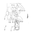
- Figure 1 is a schematic view of a preferred application for liquefied gas supply system 100, wherein system 100 is employed to supply gaseous fuel to an internal combustion engine. That is, the process fluid in this application is a combustible fuel.
- the method and system apparatus is described herein as it relates to this particular application.
- this invention is also suitable for other applications where a process fluid is stored in the liquid phase at cryogenic temperatures and it is necessary to vaporize the process fluid and deliver it to an end user that uses the process fluid in the gaseous phase and at a significantly higher temperature.
- the disclosed system and method are particularly useful for applications where there are variable operating conditions, such as, for example, applications in which process fluid flow rate varies over a wide range and/or applications in which the temperature of the heat exchange fluid in the vaporizer varies thereby affecting the heat transfer rate from the heat exchange fluid to the process fluid.
- Cryogenic storage vessel 110 comprises a double-walled vacuum insulated cryogen space 112, pump 114, which is shown disposed within cryogen space 112, drive unit 116, and level sensor 118.
- pump 114 can be disposed outside cryogen space 112 and connected thereto by an insulated suction pipe.
- Pump 114 can be designed to supply gaseous fuel to the engine at high pressures (above 14 MPa) and at temperatures above zero degrees Celsius.
- the illustrated liquefied gas supply system 100 is particularly suitable for supplying gaseous fuel to a direct injection engine, in which the gaseous fuel is injected directly into the combustion chamber, since the gaseous fuel pressure in such systems must be higher than the in-cylinder pressure, and fuel temperature must not be so low as to undesirably cool the combustion chamber.
- drive unit 116 is hydraulically driven.
- Hydraulic pump 120 supplies high pressure hydraulic fluid to flow switching device 122 through pressure line 124, and hydraulic fluid is returned to a hydraulic fluid reservoir or directly back to the hydraulic circuit through return line 126.
- Flow switching device 122 comprises valves for switching fluid connections to opposite ends of the hydraulic cylinder between pressure line 124 and return line 126 to cause reciprocating movement of a hydraulic piston disposed within the hydraulic cylinder.
- Other types of variable speed drive units can be employed.
- the drive unit could be pneumatic, electric, electromagnetic, or another type of linear motor, or a rotary drive unit with a transmission device, such as crank and rod arrangement, for converting rotary motion into linear motion.
- Vaporizer 132 is operable to raise the temperature of the fluid and shift it into the gaseous phase, so that a high pressure gas exits vaporizer 132 and flows to fuel conditioning module 140 through conduit 135.
- Vaporizer 132 is typically a heat exchanger designed to vaporize the cryogenic fluid by transferring heat energy to the cryogenic fluid from a warmer heat exchange fluid that is supplied through conduit 133.
- the warmer heat exchange fluid can be the engine coolant that is directed to conduit 133 from the engine's cooling jacket.
- the coolant exits the engine's cooling jacket with a temperature of between 80 and 95 degrees Celsius when the engine is operating under normal conditions.
- the engine coolant exits vaporizer 132 through conduit 134 and can be returned to a reservoir from which it can be recirculated through the engine's cooling system.
- Engine coolant temperature can vary depending upon many factors such as ambient air temperature, vehicle speed, and how long the engine has been running. If all other variables remain constant, cooler engine coolant temperatures result in a cooler fuel stream exiting vaporizer 132.
- An objective of the present invention is to prevent the temperature of the process fluid from dropping below a predetermined value.
- the disclosed apparatus comprises temperature sensor 136 that measures the temperature of the gas that exits from vaporizer 132 in conduit 135.
- the instrumentation can optionally also include temperature sensor 132A that measures the temperature of the process fluid inside and near the outlet of vaporizer 132 and temperature sensor 139 that measures the temperature of the heat exchange fluid that exits vaporizer 132.
- the temperatures measured by sensor 136 and/or sensor 132A and/or sensor 139 can be relayed to controller 150, which processes that information as described below when the method is discussed.
- FIG. 1 shows accumulator vessel 138 as a component of system 100.
- Accumulator vessel 138 provides a store of high-pressure gas, which, once filled, helps to reduce fluctuations in gas pressure by ensuring an adequate supply of gas at the desired pressure.
- the gas pressure in the accumulator can be higher than the gas pressure needed by the end user, so that a pressure regulating valve is employed to reduce gas pressure before it is delivered to the end user.
- the pressure regulating valve can be part of fuel conditioning module 140.
- Branch conduit 137 fluidly connects conduit 135 to accumulator vessel 138.
- the accumulator can be a vessel as shown in Figure 1 , but the accumulator can also be in the form of an inline vessel or coil, or conduit 134 itself can be sized with a diameter that provides an adequate storage volume to act as an accumulator.
- Fuel conditioning module 140 can perform a number of functions. As discussed in the previous paragraph, one of the main functions of fuel conditioning module 140 can be to control the pressure of the fuel in conduit 142, which supplies fuel gas to fuel injection valve 144. Fuel conditioning module 140 can comprise pressure sensors for measuring the gas pressure in conduit 135 and/or conduit 142, a filter for separating solid contaminants, and/or safety devices such as a pressure relief valve for preventing over-pressurization of fuel conduit 142 and/or to reduce the fuel pressure in fuel conduit 142 when the engine is shut down. The components of fuel conditioning module 140 are preferably integrated to reduce the number of connections where leaks can develop, to reduce the size, and to reduce the labor needed to assemble this module.
- Controller 150 can be part of the engine controller or a separate controller that works in cooperation with the engine controller.
- controller 150 is an electronic control module that receives input signals representative of operational parameters, processes such input signals, and emits control signals to control the operation of the fuel delivery system. Responsive to the processed input signals, controller 150 is programmed to send predetermined control signals to hydraulic pump 120, flow switching device 122, and fuel conditioning module 140. When controller 150 is integrated with the engine controller it also sends control signals to fuel injection valve 144.
- dashed lines illustrate paths for signals flowing to and from controller 150. Each line can represent a plurality of signal wires if more than one input or control signal is transmitted between controller 150 and a given fuel system component.
- FIG. 2 is an illustration of another embodiment of a fuel delivery system for a gaseous-fuelled internal combustion engine.
- Fuel delivery system 200 is similar to the embodiment of Figure 1 with some exceptions, as noted below.
- Two storage vessels are shown, namely 210A and 210B, but as will be appreciated by persons skilled in the technology, any number of storage vessels can be employed by the presently disclosed invention.
- Each storage vessel defines its own cryogen space 212A and 212B, respectively, with each served by its own respective pump 214A, 214B.
- Separate drive units 216A and 216B allows can allow independent operation of respective pumps 214A and 214B.
- the vaporizers are integrated into the pump assembly as described with respect to Figure 3 . Accordingly high-pressure gas exits straight from the pump assemblies into conduit 230. Temperature sensors 236A and 236B measure the temperature of the process fluid exiting from respective pumps 214A and 214B. The temperature sensors send signals representative of the measured temperature to controller 250.
- accumulator vessel 238, fuel conditioning module 240 and fuel injection valve 244 function in the same way as accumulator vessel 138, fuel conditioning module 140 and fuel injection valve 144 that have all been described in relation to the embodiment of Figure 1 .
- FIG 3 is an illustration of a vaporizer that can be made integral to the pump assembly as described with respect to the embodiment of Figure 2 .
- a combined pump and vaporizer arrangement is disclosed in co-owned Canadian patent no. 2,362,881 , entitled, "Method and Apparatus For Delivering Pressurized Gas".
- a heater that can act as vaporizer 300 can be disposed in the annular space that surrounds the pump drive shaft, with this space being insulated from the cryogen space and the cold end where the pump chamber is located.
- the process fluid pumped from the cryogenic storage vessel enters the vaporizer through inlet coupling 302 from which it is introduced into introduction tube 304.
- heater introduction tube 304 preferably directs the pressurized fluid to a location proximate to where the heat exchange fluid is first introduced into the heater.
- heat exchange fluid is first introduced into inner heat bath channel 306 near drive head flange 307. Accordingly, the coldest part of inner coil 308 is exposed to the warmest part of the heat bath.
- the heat exchange fluid flows through inner channel 306 and outer channel 309 in the same general direction as the pressurized fluid flowing through inner tubular coil 308 and then outer tubular coil 310.
- the length of the pressurized fluid coil within the heat bath is determined so that the pressurized fluid exits vaporizer 300 as a gas that has been heated to a temperature within a pre-determined temperature range.
- the engine coolant is an example of a suitable and convenient heat exchange fluid that can be delivered to the vaporizer.
- engine coolant that has been heated after passing through the cooling jacket of the engine can be delivered to the heat bath in vaporizer 300 where it is cooled prior to being returned to the engine cooling system.
- the quantity of engine coolant that is diverted to the vaporizer can be only a relatively small portion of the total engine coolant flow, such that there is not a significant change to the overall heat balance within the engine cooling system compared to a conventional engine cooling system that does not divert any engine coolant to a vaporizer.
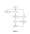
- FIG 4 illustrates a method that can be used to operate the system of Figure 1 and in the description of this method, component reference numbers refer to the components illustrated in Figure 1 .
- the method starts with a pressure sensor measuring process fluid pressure downstream from vaporizer 132.
- the pressure sensor can be a part of fuel conditioning module 140.
- the measured pressure is monitored by controller 150 and if process fluid pressure P is less than predetermined low pressure threshold P L the controller takes this as an overall request to start the pump.
- controller 150 monitors the measurements from temperature sensor 136, which indicates the temperature of the process fluid downstream from vaporizer 132. If controller 150 determines that T f is not less than threshold temperature T L , then controller 150 commands pump 114 to stroke to thereby raise the process fluid pressure.
- controller 150 determines that T f is less than T L , then controller 150 imposes a predetermined wait time t before commanding pump 114 to stroke.
- the imposed wait time allows more residency time for the process fluid in vaporizer 132, allowing more time for it to be heated.
- controller 150 can be programmed to suspend operation of pump 114 until T f is greater than T L . After pump 114 is stroked, controller 150 determines if process fluid pressure P is less than predetermined high pressure threshold P H .
- An objective of this aspect of the method is to maintain process fluid pressure between low pressure threshold pressure P L and high pressure threshold pressure P H .
- controller 150 determines that process fluid pressure P is less than high pressure threshold pressure P H then controller 150 again considers whether T f is less than threshold temperature T L , before commanding another pump stroke. If T f is less than T L the pump may be temporarily suspended from operating before process fluid pressure is raised up to P H , so that process fluid pressure cycles between P L and an intermediate pressure between P L and P H until T f remains higher than T L for the number of pump strokes that is needed to raise process fluid pressure to P H . When controller 150 determines that process fluid pressure P is not less than P H , then controller 150 returns to the start and waits until process fluid pressure P is less than P L .
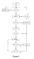
- Figure 5 illustrates another method of operating the system of Figure 1 .
- the method of Figure 5 includes all of the steps of the method of Figure 4 , but with some additional steps.
- Controller 150 considers whether n is greater than a predetermined number N as a further condition to determining if it will temporarily suspend operation of pump 114. Using a counter in this manner helps controller 150 to filter out false temperature readings, so that pump 114 is only suspended from operating if process fluid temperature T f is lower than T L for N consecutive pump cycles.
- T L can be set higher than if a counter is not used.
- controller 150 can impose a predetermined wait time before resetting n to zero and then commanding the pump to stroke, or as shown in Figure 5 , the method can optionally further comprise other additional steps , which relate to considering the temperature of the heat exchange fluid or the process fluid inside the vaporizer.
- the temperature of the heat exchange fluid can be measured by temperature sensor 139 and/or the process fluid temperature inside vaporizer 132 can be measured by temperature sensor 132A.
- controller 150 imposes a delay to resetting n to zero and stroking pump 114 until the wait time is greater than a predetermined maximum wait time t max , or until heat exchange fluid temperature Tc is greater than a predetermined minimum temperature T m . If temperature T c is not greater than T m , and the wait time is less than t max , controller 150 continues to suspend operation of pump 114. If the controller determines that T c is greater than T m , before total wait time is greater than t max , controller 150 can immediately reset the counter to zero and controller 150 can then command pump 114 to stroke if needed to raise process fluid pressure P and maintain it within the range between P L and P H .
- Figure 6 illustrates a method that can be used to operate the system of Figure 2 , which has a parallel arrangement for storage vessels 210A, 210B, pumps 214A, 214B with parallel vaporizers integrated with the pump assemblies.
- the method is the same as the methods of Figures 4 and 5 in that the pumps are temporarily suspended from operating when the process fluid temperature T f drops below a predetermined threshold temperature T L , but with the parallel arrangement, when one pump is suspended from operating it is possible to switch to the other pump.
- the method of Figure 6 begins with controller 250 determining if there is a need to increase process fluid pressure by checking if process fluid pressure P is less than predetermined low pressure threshold P L . If process fluid pressure P is not less than predetermined low pressure threshold P L , then controller 250 waits until process fluid pressure P does indeed drop below predetermined low pressure threshold P L before checking temperature T f1 which is measured by temperature sensor 236A downstream from pump 214A and its integral vaporizer. If process fluid pressure P is less than P L , and controller 250 determines that T f1 is not less than threshold temperature T L then controller 250 commands pump 214A (pump 1) to stroke.
- controller 250 After stroking pump 214A, if controller 250 determines that process fluid pressure P is less than predetermined high pressure threshold P H , then controller 250 again considers whether T f1 is less than T L before commanding another stroke of pump 214A. If P is not less than P H , then controller 250 waits until P is less than P L before repeating the process of determining whether to command another stroke of pump 214A or to switch to pump 214B (pump 2).
- controller 250 leaves pump 214A idle and commands pump 214B to stroke.
- the process for operating pump 214B is the same as the process for operating pump 214A except that after stroking pump 214B and controller 250 checks whether process fluid pressure P is less than P H , controller 250 checks process fluid temperature T f2 (not T f1 ) before determining which pump to stroke, where process fluid temperature T f2 is measured by temperature sensor 236B downstream from pump 214B. That is, if P is less than P H , pump 214B is commanded to take another stroke if T f2 is not less than T L .
- controller 250 commands pump 214A to stroke. If, after stroking pump 214B process fluid pressure P is not less than P H , then controller 250 waits until P is less than P L before again considering whether to command another stoke of pump 214B or to shift to pump 214A if T f2 is less than T L .
- the minimum time that each of the pumps is idle is the time that it takes for the other pump to complete an extension and retraction stroke.
- the idle time for each pump can be longer than this minimum time and typically is longer depending upon a number of system characteristics such as the flow capacity of the pumps relative to the normal consumption rates by the end user, the size of the accumulator volume, and the efficiency of the vaporizer.
- Figure 7 illustrates another embodiment of a method of controlling the system of Figure 2 . Similar to both methods, the controller can determine from the process fluid temperature when to switch from one pump to the other pump. However, with this method, a pump can be enabled to stroke even if the measured process fluid temperature is less than T L , if idle time ti for that pump is not less than predetermined maximum time t max . Another difference between the method of Figure 7 and the method of Figure 6 is that, in the method of Figure 7 , when controller 250 determines that one pump should be idle, before commanding the other pump to stroke controller 250 considers whether the process fluid temperature associated with the other pump is less than T L or if the idle time ti for the other pump is less than t max .
- both T f1 and T f2 are less than T L and t i for both pumps is less than t max , this can result in a condition where both pump 214A and pump 214B are idle until one of T f1 or T f2 rises above T L or t i for one of the pumps is greater than t max . Because T f1 and T f2 are measured by respective sensors 136A and 136B which are downstream from the vaporizers, when both pumps are idle the process fluid temperature measured by the temperature sensors may not reflect the temperature of the process fluid within the vaporizers, since this fluid continues to be warmed by the heat exchange fluid and there is virtually no mass flow through conduit 230.
- this method further comprises setting a predetermined maximum idle time t max , whereby if both T f1 and T f2 are less than T L , after one of the pumps has been idle for at least the maximum idle time, that pump can be allowed to stroke, even if both T f1 and T f2 remain less than T L .
- additional temperature sensors can be employed, similar to those shown in Figure 1 to measure heat exchange fluid temperature or process fluid temperature within the vaporizer, whereby one of the pumps can be allowed to stroke if heat exchange fluid temperature or process fluid temperature within the vaporizer is above a predetermined value.
- the controller can be programmed to consider the temperature of the heat exchange fluid or the process fluid inside the vaporizer in lieu of the maximum idle time control strategy or in combination, whereby a pump can be allowed to stroke even if the downstream process fluid temperature is less than T L and idle time t i is less than t max , if one of heat exchange fluid temperature or process fluid temperature inside the respective vaporizer is above a predetermined value.
- two temperature sensors (236A and 236B) are employed to measure process fluid temperature downstream from respective pump/vaporizer assemblies 214A and 214B.
- temperature sensors 236A and 236B are positioned in the conduits between the respective vaporizers and check valves that prevent backflow when a pump is idle and the other pump is operating.
- a single temperature sensor can be employed to monitor when process fluid pressure temperature T f is below predetermined low temperature threshold T L .
- the method is the same as those set out in Figures 6 and 7 , except that T f replaces T f1 and T f2 .
- Figure 8 is a graph that further illustrates a method such as one of those illustrated by Figure 6 or Figure 7 applied to a two-pump system such as that of Figure 2 .
- Figure 8 is a plot of process fluid temperate against time. Superimposed on the same graph, Figure 8 also plots, pump piston displacement against the same time scale.
- the vertical axis is process fluid temperature measured in degrees Celsius at the outlet of the vaporizer, and the horizontal axis is time measured in seconds.
- the threshold temperature T L is minus 40 degrees Celsius, and this is marked in Figure 8 by a horizontal dashed line.
- This graph illustrates a start-up mode, when process fluid pressure is below the desired pressure and several consecutive pump strokes are needed to pressurize the system. As already noted in this disclosure, this is a challenging operating condition because when the heat exchange fluid is engine coolant, if the temperature of the engine block is initially cold, the engine coolant temperature can be much colder than normal operating conditions.
- first pump 214A is commanded to start, as indicated at the ten second mark by line 812.
- the peaks of lines 812 represent when the pump piston is fully extended and the baseline indicates when the piston is fully retracted.
- Line 812 shows that first pump 214A is operated for six consecutive pump strokes until, as indicated by line 810, the temperature downstream from pump 214A drops to below threshold temperature T L .
- controller 250 commands pump 214A to temporarily suspend operation, thereby increasing residency time in the associated vaporizer, which results in an increase in the process fluid temperature.
- process fluid pressure is still below the desired system pressure, and since process fluid temperature downstream from second pump 214B, as indicated by line 820, is higher than threshold temperature T L , controller 250 commands second pump 214B to stroke, as indicated by line 822.
- peaks in line 822 correspond to when the pump piston is fully extended and the baseline corresponds to when the pump piston is fully retracted.
- the temperature downstream from second pump 214B is at about minus 5 degrees Celsius, but after four piston strokes, as shown by line 820, process fluid temperature downstream from second pump 214B drops below threshold temperature T L , and controller 250 commands second pump 214B to temporarily suspend operation. After second pump 214B is suspended, process fluid temperature downstream from second pump 214B begins to rise. Meanwhile, in the time that first pump 214A has been suspended, line 810 shows that process fluid temperature downstream from first pump 214A has risen above T L , enabling first pump 214A to be ready to be restarted when needed. As shown in this example, when pump 214B is suspended, at about the 35 second mark, controller 250 commands first pump 214A to restart and stroke again.
- Figure 8 illustrates an extreme operating condition, namely start-up when continuous pumping is initially required to raise system pressure.
- Figure 8 also shows that once the system is pressurized, intermittent operation of the pumps can be sufficient to maintain system pressure.
- a large accumulator volume can reduce the frequency of operating the pump, allowing more residency time of the process fluid in the vaporizer.
- the accumulator volume is excessively large, it can be difficult at start up to pressurize the system.
- the pump is stroked when system pressure drops to low pressure threshold P L and as long as process fluid temperature remains above threshold temperature T L the pump can be commanded to stroke until system pressure reaches a predetermined high pressure set point, thereby maintaining system pressure between a predetermined high pressure set point and a predetermined low pressure threshold.
- process fluid temperature drops below threshold temperature T L and the pump can be temporarily suspended before system pressure reaches the high pressure set point, system pressure can fluctuate between the predetermined low pressure threshold and an intermediate system pressure.
- FIGS. 4 through 7 are provided to help illustrate different embodiments of the method, with some embodiments comprising additional steps for controlling the operation of the pump(s).
- Persons skilled in implementation of control strategies will understand that the steps need not follow the depicted order to achieve the same results, and that steps need not be performed in a sequential manner. That is, a controller can be programmed to monitor, in parallel, several parameters such as, for example, process fluid temperature, process fluid pressure, heat exchange fluid temperature, how long a pump has been idle, and how many consecutive pump strokes have been made with process fluid temperature below a threshold temperature. Each parameter can be determinative of whether or not the pump is ready to be stroked.
- both pumps can be enabled for operation, or one of the pumps, or none of the pumps.
- the controller determines that it is necessary to increase process fluid pressure, if both pumps are enabled, to determine which pump to operate, the controller can choose a pump based upon other criteria such as respective pump performance, fluid level in the respective storage vessels, and which pump has been idle longer.
Landscapes
- Engineering & Computer Science (AREA)
- Chemical & Material Sciences (AREA)
- Mechanical Engineering (AREA)
- General Engineering & Computer Science (AREA)
- Combustion & Propulsion (AREA)
- Chemical Kinetics & Catalysis (AREA)
- General Chemical & Material Sciences (AREA)
- Oil, Petroleum & Natural Gas (AREA)
- Filling Or Discharging Of Gas Storage Vessels (AREA)
Claims (20)
- Procédé destiné à pomper un fluide de process à partir d'un récipient (110, 210A, 210B) de stockage cryogénique et à amener ledit fluide de process à un consommateur final dans une phase gazeuse, ledit procédé comportant les étapes consistant à :mettre en marche une pompe (114, 214A, 214B) et pomper ledit fluide de process à partir dudit récipient (110, 210A, 210B) de stockage, mettant ainsi sous pression ledit fluide de process, lorsque la pression du fluide de process mesurée en aval de ladite pompe (114, 214A, 214B) est inférieure à un seuil prédéterminé de basse pression ;arrêter ladite pompe (114, 214A, 214B) lorsque ladite pression du fluide de process est supérieure à un seuil prédéterminé de haute pression ;diriger ledit fluide de process de ladite pompe (114, 214A, 214B) vers un vaporiseur (132) et transférer de la chaleur d'un fluide d'échange de chaleur audit fluide de process pour convertir ledit fluide de process d'une forme liquéfiée en ladite phase gazeuse ;amener ledit fluide de process dudit vaporiseur (132) audit consommateur final ;caractérisé en ceque le procédé comporte en outre les étapes consistant à :mesurer la température du fluide de process après que ledit fluide de process a quitté ledit vaporiseur (132) et suspendre temporairement le fonctionnement de ladite pompe (114, 214A, 214B) lorsque :(i) ladite température du fluide de process est inférieure à une température seuil prédéterminée ; ou(ii) ladite température du fluide de process est inférieure à une température seuil prédéterminée pendant un nombre prédéterminé de cycles consécutifs de pompe ; etremettre en marche ladite pompe (114, 214A, 214B) qui a été suspendue si au moins une condition prédéfinie de validation est satisfaite et si la pression du fluide de process est inférieure audit seuil prédéterminé de haute pression.
- Procédé selon la revendication 1, ladite pompe (114, 214A, 214B) étant temporairement suspendue lorsque ladite température du fluide de process est inférieure à ladite température seuil prédéterminée pendant ledit nombre prédéterminé de cycles consécutifs de pompe.
- Procédé selon la revendication 1 ou 2, une desdites conditions prédéfinies de validation étant satisfaite lorsque :(i) ladite pompe (114, 214A, 214B) a été suspendue pendant un laps de temps minimal prédéterminé ; et / ou(ii) ledit fluide de process présente une température en aval dudit vaporiseur (132) qui est supérieure à ladite température seuil prédéterminée ; et / ou(iii) ledit fluide d'échange de chaleur présente une température mesurée en aval dudit vaporiseur (132) qui est supérieure à une température prédéterminée ; et / ou(iv) ledit fluide de process présente une température à l'intérieur dudit vaporiseur (132) qui est supérieure à une température prédéterminée.
- Procédé selon l'une quelconque des revendications précédentes, ledit fluide de process étant un carburant et ledit procédé comportant en outre l'étape consistant à amener ledit carburant à une chambre de combustion d'un moteur à combustion interne.
- Procédé selon la revendication 4, comportant en outre l'étape consistant à injecter au moins une partie dudit carburant via un injecteur (144, 244) de carburant directement dans ladite chambre de combustion.
- Procédé selon la revendication 4 ou 5, ledit fluide d'échange de chaleur étant un liquide de refroidissement du moteur et ledit procédé comportant en outre l'étape consistant à diriger ledit liquide de refroidissement du moteur d'un système de refroidissement du moteur vers ledit vaporiseur (132).
- Procédé selon la revendication 6, comportant en outre l'étape consistant à diriger ledit liquide de refroidissement du moteur vers ledit vaporiseur (132) à partir d'une sortie d'une chemise de refroidissement dudit moteur.
- Procédé selon l'une quelconque des revendications précédentes, ledit récipient (110, 210A, 210B) de stockage étant le premier de deux récipients (110, 210A, 210B) de stockage, ladite pompe (114, 214A, 214B) étant la première de deux pompes (114, 214A, 214B), et ledit vaporiseur (132) étant le premier de deux vaporiseurs (132), et ledit procédé comportant en outre les étapes consistant à :mettre en marche une deuxième pompe (114, 214A, 214B) et pomper ledit fluide de process à partir d'un deuxième récipient (110, 210A, 210B) de stockage, mettant ainsi sous pression ledit fluide de process, lorsque le fonctionnement de ladite première pompe (114, 214A, 214B) est temporairement suspendu, au moins une condition prédéfinie de validation pour ladite deuxième pompe (114, 214A, 214B) étant satisfaite et ladite pression du fluide de process en aval de ladite deuxième pompe (114, 214A, 214B) étant inférieure audit seuil prédéterminé de haute pression ;arrêter ladite deuxième pompe (114, 214A, 214B) lorsque ladite pression du fluide de process est supérieure audit seuil prédéterminé de haute pression ;diriger ledit fluide de process de ladite deuxième pompe (114, 214A, 214B) vers un deuxième vaporiseur (132) et transférer de la chaleur dudit fluide d'échange de chaleur audit fluide de process pour convertir ledit fluide de process d'une forme liquéfiée en ladite phase gazeuse ;amener ledit fluide de process dudit deuxième vaporiseur (132) audit consommateur final ;mesurer la température du fluide de process après que ledit fluide de process a quitté ledit deuxième vaporiseur (132) et suspendre temporairement le fonctionnement de ladite deuxième pompe (114, 214A, 214B) lorsque ladite température du fluide de process en aval dudit deuxième vaporiseur (132) est inférieure à ladite température seuil prédéterminée ;remettre en marche ladite première pompe (114, 214A, 214B) si au moins une condition prédéfinie de validation pour la remise en marche de ladite première pompe (114, 214A, 214B) est satisfaite, ladite deuxième pompe (114, 214A, 214B) étant temporairement suspendue et la pression du fluide de process étant inférieure au seuil prédéterminé de haute pression ; etremettre en marche ladite deuxième pompe (114, 214A, 214B) si au moins une condition prédéfinie de validation pour la remise en marche de ladite deuxième pompe (114, 214A, 214B) est satisfaite, ladite première pompe (114, 214A, 214B) étant temporairement suspendue et la pression du fluide de process étant inférieure au seuil prédéterminé de haute pression.
- Procédé selon la revendication 8, une desdites conditions prédéfinies de validation pour la remise en marche de l'une desdites première et deuxième pompes (114, 214A, 214B) dont le fonctionnement a été suspendu étant satisfaite lorsque :(i) l'autre pompe (114, 214A, 214B) a effectué la course de pompe précédente ; et / ou(ii) la température du fluide de process mesurée en aval de ladite pompe suspendue (114, 214A, 214B) est supérieure audit seuil prédéterminé de température ; et /ou(iii) ladite pompe suspendue (114, 214A, 214B) a été au repos pendant un laps de temps minimal prédéterminé ; et / ou(iv) la température du fluide de process mesurée à l'intérieur dudit vaporiseur (132) qui est associé à ladite pompe suspendue (114, 214A, 214B) est supérieure à une température prédéterminée ; et / ou(v) lorsque la température du fluide d'échange de chaleur mesurée à la sortie dudit vaporiseur (132) qui est associé à ladite pompe suspendue (114, 214A, 214B), est supérieure à une température prédéterminée.
- Système d'amenée de fluide comportant des composants qui coopèrent entre eux pour stocker un fluide de process liquéfié et amener ledit fluide de process dans une phase gazeuse à un consommateur final, ledit système d'amenée de fluide comportant :un récipient (110, 210A, 210B) de stockage servant à contenir ledit fluide de process liquéfié à des températures cryogéniques ;une pompe (114, 214A, 214B) dotée d'une entrée d'aspiration en communication fluidique avec un espace pour cryogène à l'intérieur dudit récipient (110, 210A, 210B) de stockage ;un vaporiseur (132) doté d'une entrée en communication fluidique avec une sortie de refoulement de ladite pompe (114, 214A, 214B), ledit vaporiseur (132) comportant un échangeur de chaleur servant à transférer une énergie thermique d'un fluide d'échange de chaleur audit fluide de process, ladite énergie thermique étant ainsi susceptible d'être employée pour convertir ledit fluide de process liquéfié en ladite phase gazeuse ;un conduit (135) en communication fluidique avec une sortie dudit vaporiseur (132) pour amener ledit fluide de process audit consommateur final; etun capteur de pression disposé dans ledit conduit (135) pour mesurer la pression du fluide de process et émettre un signal électronique représentatif de la pression du fluide de process ;caractérisé en ceque ledit système d'amenée de fluide comporte en outre :un capteur (136, 236A, 236B) de température disposé dans ledit conduit pour mesurer la température du fluide de process et émettre un signal électronique représentatif de ladite température du fluide de process ; etune commande (150, 250) en communication avec ledit capteur (136, 236, 236B) de température et ledit capteur de pression, ladite commande étant programmable pour commander le fonctionnement des pompes en réaction à la température et à la pression du fluide de process, ladite commande étant ainsi :prévue pour donner comme consigne à ladite pompe (114, 214A, 214B) de fonctionner lorsque la pression du fluide de process est inférieure à un seuil prédéterminé de basse pression ;prévue pour donner comme consigne à ladite pompe (114, 214A, 214B) de s'arrêter lorsque la pression du fluide de process est supérieure à un seuil prédéterminé de haute pression ;prévue pour donner comme consigne à ladite pompe (114, 214A, 214B) de suspendre temporairement le fonctionnement lorsque la température du fluide de process est inférieure à une température seuil prédéterminée, cette consigne de suspension du fonctionnement ayant la priorité sur une consigne de faire fonctionner ladite pompe (114, 214A, 214B) basée sur la pression du fluide de process ; etprévue pour donner comme consigne à ladite pompe (114, 214A, 214B) de redémarrer à partir d'une suspension de fonctionnement si au moins une condition prédéfinie de validation est satisfaite et si la pression du fluide de process est inférieure au seuil prédéterminé de haute pression.
- Système d'amenée de fluide selon la revendication 10, une desdites conditions prédéfinies de validation étant satisfaite lorsque :(i) ladite pompe (114, 214A, 214B) qui a été suspendue a été au repos pendant au moins un laps de temps minimal prédéterminé ; et / ou(ii) ladite température du fluide de process dans ledit conduit (135) est supérieure à ladite température seuil prédéterminée.
- Système d'amenée de fluide selon la revendication 10, comportant en outre un capteur (132A, 139) de température disposé dans :(i) un conduit de sortie pour fluide d'échange de chaleur quittant ledit vaporiseur (132), à partir duquel des signaux électroniques représentatifs de la température dudit fluide d'échange de chaleur sont susceptibles d'être envoyés à ladite commande (150, 250), et une desdites conditions prédéfinies de validation étant satisfaite lorsque ledit fluide d'échange de chaleur présente une température qui est supérieure à une température prédéterminée ; ou(ii) un passage de fluide de process à l'intérieur dudit vaporiseur (132) à partir duquel des signaux électroniques représentatifs du fluide de process sont susceptibles d'être envoyés à ladite commande (150, 250), et une desdites conditions prédéfinies de validation étant satisfaite lorsque la température du fluide de process à l'intérieur dudit vaporiseur (132) est supérieure à une température prédéterminée.
- Système d'amenée de fluide selon l'une quelconque des revendications 10 à 12, comportant en outre :(i) un récipient accumulateur (138, 238) servant à contenir du gaz sous pression en aval dudit vaporiseur (132) et en amont dudit consommateur final ; et / ou(ii) un régulateur de pression associé audit conduit (135) pour réguler la pression de gaz avant qu'il soit amené jusqu'audit consommateur final.
- Système d'amenée de fluide selon l'une quelconque des revendications 10 à 13. ledit consommateur final étant un moteur à combustion interne, et ledit fluide de process étant un carburant combustible, et ledit conduit (135) étant prévu pour amener ledit carburant à un injecteur (144, 244) de carburant.
- Système d'amenée de fluide selon la revendication 14, ledit injecteur (144, 244) de carburant comprenant un ajutage disposé dans une chambre de combustion dudit moteur, ledit carburant pouvant ainsi être introduit directement dans une chambre de combustion dudit moteur.
- Système d'amenée de fluide selon la revendication 14 ou 15, ledit moteur étant la machine motrice d'un véhicule.
- Système d'amenée de fluide selon l'une quelconque des revendications 14 à 16, ledit fluide d'échange de chaleur étant un liquide de refroidissement du moteur et ledit système comportant en outre une tuyauterie reliant une chemise de refroidissement dudit moteur à une entrée de fluide d'échange de chaleur dudit vaporiseur (132).
- Système d'amenée de fluide selon l'une quelconque des revendications 10 à 17, ladite pompe (114, 214A, 214B) étant disposée à l'intérieur de l'espace pour cryogène dudit récipient (110, 210A, 210B) de stockage.
- Système d'amenée de fluide selon l'une quelconque des revendications 10 à 18, ledit récipient (110, 210A, 210B) de stockage, ladite pompe (114, 214A, 214B) et ledit vaporiseur (132) appartenant chacun à une pluralité de composants similaires agencés en parallèle, chacun desdits vaporiseurs (132) comportant une sortie en communication avec ledit conduit (135), ladite commande (150, 250) étant programmable pour mettre en marche une pompe de ladite pluralité de pompes (114, 214A, 214B) qui est au repos lorsque le fonctionnement d'une autre desdites pompes (114, 214A, 214B) est temporairement suspendu, si au moins une condition prédéfinie de validation est satisfaite et si la pression du fluide de process est inférieure audit seuil prédéterminé de haute pression.
- Système d'amenée de fluide selon la revendication 19, comportant en outre un capteur (136, 236A, 236B) de température respectif servant à mesurer :(i) la température du fluide de process entre chacune des sorties dudit vaporiseur (132) et des clapets anti-retour respectifs en amont dudit conduit (135) ; ou(ii) la température du fluide d'échange de chaleur près d'une sortie de fluide d'échange de chaleur pour chaque vaporiseur (132) et ladite commande (150, 250) étant programmable pour valider le fonctionnement d'une pompe (114, 214A, 214B) si la température du fluide d'échange de chaleur pour un vaporiseur (132) respectif est supérieure à une valeur prédéterminée ; ou(iii) la température du fluide de process à l'intérieur de chaque vaporiseur (132) et ladite commande (150, 250) étant programmable pour valider le fonctionnement d'une pompe (114, 214A, 214B) si la température du fluide de process à l'intérieur d'un vaporiseur (132) respectif est supérieure à une valeur prédéterminée.
Applications Claiming Priority (2)
| Application Number | Priority Date | Filing Date | Title |
|---|---|---|---|
| CA002523732A CA2523732C (fr) | 2005-11-10 | 2005-11-10 | Systeme et methode de livraison d'un gaz comprime a partir d'un recipient de stockage cryogenique |
| PCT/CA2006/001838 WO2007068081A1 (fr) | 2005-11-10 | 2006-11-08 | Systeme et procede de distribution d'un gaz sous pression a partir d'un recipient de stockage cryogenique |
Publications (3)
| Publication Number | Publication Date |
|---|---|
| EP1945997A1 EP1945997A1 (fr) | 2008-07-23 |
| EP1945997A4 EP1945997A4 (fr) | 2010-03-17 |
| EP1945997B1 true EP1945997B1 (fr) | 2014-08-27 |
Family
ID=36242575
Family Applications (1)
| Application Number | Title | Priority Date | Filing Date |
|---|---|---|---|
| EP20060848623 Active EP1945997B1 (fr) | 2005-11-10 | 2006-11-08 | Systeme et procede de distribution d'un gaz sous pression a partir d'un recipient de stockage cryogenique |
Country Status (6)
| Country | Link |
|---|---|
| US (2) | US20080226463A1 (fr) |
| EP (1) | EP1945997B1 (fr) |
| CN (1) | CN101305239B (fr) |
| AU (1) | AU2006324322B2 (fr) |
| CA (1) | CA2523732C (fr) |
| WO (1) | WO2007068081A1 (fr) |
Cited By (1)
| Publication number | Priority date | Publication date | Assignee | Title |
|---|---|---|---|---|
| WO2023133328A1 (fr) * | 2022-01-07 | 2023-07-13 | Integrated Cryogenic Solutions, LLC | Minimisation d'un écoulement de recyclage dans le fonctionnement d'une pompe |
Families Citing this family (50)
| Publication number | Priority date | Publication date | Assignee | Title |
|---|---|---|---|---|
| CA2527563C (fr) * | 2005-12-23 | 2007-07-03 | Westport Research Inc. | Appareil et methode pour le pompage d'un fluide cryogenique a partir d'un recipient de stockage et pour l'etablissement de diagnostic des performances de la pompe cryogenique |
| CA2602164A1 (fr) | 2007-10-04 | 2007-12-18 | Westport Power Inc. | Systeme de commande hydraulique et strategie de controle diagnostique pour fonctionnement ameliore |
| US8833088B2 (en) * | 2009-09-08 | 2014-09-16 | Questar Gas Company | Methods and systems for reducing pressure of natural gas and methods and systems of delivering natural gas |
| US8613201B2 (en) * | 2009-09-08 | 2013-12-24 | Questar Gas Company | Methods and systems for reducing pressure of natural gas and methods and systems of delivering natural gas |
| US20110192465A1 (en) * | 2010-02-09 | 2011-08-11 | Mission Communications, Llc | Vacuum Sewer Valve Fault Detection System |
| US20110214644A1 (en) * | 2010-03-05 | 2011-09-08 | Woodward, Inc. | Cold-Start Fuel Control System |
| CN103619705A (zh) * | 2011-05-31 | 2014-03-05 | 大宇造船海洋株式会社 | 使用lng燃料的寒热回收设备及包含此设备的液化气运输船 |
| CA2754183C (fr) * | 2011-10-05 | 2013-01-08 | Westport Power Inc. | Module de gestion du debit massique et d'amortissement des pulsations de pression dans une conduite d'alimentation en carburant gazeux |
| CA2758246C (fr) | 2011-11-16 | 2013-02-12 | Westport Power Inc. | Procede et appareil pour pomper du carburant dans un systeme d'injection de carburant |
| CA2762697C (fr) | 2011-12-22 | 2021-04-27 | Westport Power Inc. | Procede et appareil d'approvisionnement d'un moteur a combustion interne en carburant gazeux |
| JP6026648B2 (ja) * | 2012-05-16 | 2016-11-16 | テーゲーエー、マリン、ガス、エンジニヤリング、ゲーエムベーハー | ガス供給装置 |
| US9234452B2 (en) | 2012-05-17 | 2016-01-12 | Caterpillar Inc. | Direct injection gas engine and method |
| US20130306029A1 (en) * | 2012-05-17 | 2013-11-21 | Caterpillar Inc. | Direct Injection Gas Engine and Method |
| CN102777286A (zh) * | 2012-08-03 | 2012-11-14 | 中国海洋石油总公司 | 以液压驱动泵供给燃料的车用液化天然气气化器 |
| JP6283673B2 (ja) * | 2012-08-24 | 2018-02-21 | マイクロリン エルエルシー | ガスセル駆動型配向非依存性搬送装置 |
| US9115325B2 (en) * | 2012-11-12 | 2015-08-25 | Mcalister Technologies, Llc | Systems and methods for utilizing alcohol fuels |
| US20140130522A1 (en) * | 2012-11-13 | 2014-05-15 | Caterpillar Inc. | Liquefied Gas Supply Conditioning System and Method |
| CN102966468B (zh) * | 2012-11-19 | 2015-06-03 | 福州大学 | Lng绕管式汽化器 |
| CN103047537B (zh) * | 2012-12-19 | 2015-09-02 | 湖北三江航天红阳机电有限公司 | 一种游艇lng防爆供气控制系统 |
| US9188069B2 (en) | 2012-12-27 | 2015-11-17 | Caterpillar Inc. | Gaseous fuel system, direct injection gas engine system, and method |
| CA2809495C (fr) * | 2013-03-15 | 2014-06-03 | Westport Power Inc. | Regulation thermique d'un fluide evacue par un echangeur de chaleur |
| CN103133187B (zh) * | 2013-03-21 | 2014-12-10 | 宁波明欣化工机械有限责任公司 | 一种高集成式加注汽化稳压橇 |
| CA2819721C (fr) * | 2013-06-27 | 2014-07-08 | Westport Power Inc. | Appareil de commande de moteur |
| CA2819966C (fr) * | 2013-07-05 | 2014-07-08 | Westport Power Inc. | Appareil et methode d'amelioration de l'efficacite volumetrique dans un moteur a combustion interne |
| CN103363291A (zh) * | 2013-07-26 | 2013-10-23 | 苍溪县大通天然气投资有限公司 | 一种焊割气充装设备及方法 |
| US9604655B2 (en) * | 2013-08-22 | 2017-03-28 | General Electric Company | Method and systems for storing fuel for reduced usage |
| US8958972B1 (en) * | 2013-08-23 | 2015-02-17 | General Electric Company | Method and systems for storing fuel for reduced usage |
| CA2831759C (fr) * | 2013-10-31 | 2015-01-20 | Westport Power Inc. | Appareil et procede pour faire fonctionner une pluralite de pompes hydrauliques |
| CA2831762C (fr) | 2013-10-31 | 2015-01-20 | Westport Power Inc. | Systeme et procede pour livrer un fluide stocke sous forme liquide a un utilisateur final sous forme gazeuse |
| CN103615660B (zh) * | 2013-12-03 | 2015-12-30 | 张家港市华地机械装备有限公司 | 一种利用发动机废热能的水浴式汽化器 |
| US9828987B2 (en) * | 2015-01-30 | 2017-11-28 | Caterpillar Inc. | System and method for priming a pump |
| US9915251B2 (en) * | 2015-03-26 | 2018-03-13 | Caterpillar Inc. | Fuel system having serially arranged in-tank pumps |
| CN107614962B (zh) * | 2015-04-30 | 2020-09-11 | 西港能源有限公司 | 用于低温流体系统的智能压力管理系统 |
| DE102015214191B3 (de) * | 2015-07-27 | 2016-12-08 | Mtu Friedrichshafen Gmbh | Brenngasversorgungseinrichtung zur Bereitstellung eines Brenngases und Brennkraftmaschine |
| DE102015218234A1 (de) * | 2015-09-23 | 2017-03-23 | Bayerische Motoren Werke Aktiengesellschaft | Kryogener Druckbehälter für ein Kraftfahrzeug mit einem Temperatursensor im Außenbereich eines Außenbehälters |
| CN106762167B (zh) * | 2015-11-23 | 2019-12-17 | 陕西汽车集团有限责任公司 | 一种lng车的智能供气控制系统 |
| US10030611B2 (en) | 2016-08-05 | 2018-07-24 | Caterpillar Inc. | Fuel delivery system |
| US20180346313A1 (en) * | 2017-06-05 | 2018-12-06 | Ut-Battelle, Llc | Gaseous hydrogen storage system with cryogenic supply |
| DE102018210999A1 (de) * | 2018-07-04 | 2020-01-09 | Robert Bosch Gmbh | Kraftstofffördereinrichtung für kryogene Kraftstoffe |
| EP3677770B1 (fr) | 2019-01-02 | 2022-05-25 | Carrier Corporation | Camion avec une unité de réfrigération de transport |
| CN110005946B (zh) * | 2019-04-30 | 2023-12-22 | 鞍山市昱虎流体设备有限公司 | 三分支防冰冻低温流体卸车臂 |
| BE1028135B1 (nl) * | 2020-03-10 | 2021-10-11 | Atlas Copco Airpower Nv | Werkwijze en inrichting voor het regelen van de pompsnelheid, computerprogramma en een door een computer leesbaar medium waarop het computerprogramma is opgeslagen daarbij toegepast en een pomp |
| CN111305969B (zh) * | 2020-03-31 | 2022-07-15 | 潍柴动力股份有限公司 | 一种hpdi供气系统中lng泵的控制方法和装置 |
| CN111569804B (zh) * | 2020-04-19 | 2021-09-28 | 山东三润助剂科技股份有限公司 | 一种丙烯酸酯类聚合物乳液合成装置及其使用方法 |
| CN113124315A (zh) * | 2021-04-30 | 2021-07-16 | 常州易控汽车电子股份有限公司 | 一种lng增压控制系统 |
| US20250137422A1 (en) * | 2022-02-17 | 2025-05-01 | Bennamann Services Ltd | Systems and methods for vaporization of a liquid |
| FR3134614B1 (fr) * | 2022-04-14 | 2024-03-15 | Rafaut | Dispositif aeronautique demontable de stockage de gaz liquefie |
| CN114790981B (zh) * | 2022-04-20 | 2024-02-20 | 潍柴动力股份有限公司 | 防止hpdi发动机供气系统液压泵出现短行程的方法 |
| CN116753453B (zh) * | 2023-07-06 | 2025-10-10 | 郑州朗润智能装备股份有限公司 | Lng加气站及其潜液泵撬装置 |
| CN117906058A (zh) * | 2024-01-29 | 2024-04-19 | 广西柳钢气体有限责任公司 | 氮气安全保障系统 |
Family Cites Families (17)
| Publication number | Priority date | Publication date | Assignee | Title |
|---|---|---|---|---|
| US3082690A (en) * | 1958-03-28 | 1963-03-26 | Union Carbide Corp | Blasting method and apparatus |
| US4887857A (en) * | 1986-07-22 | 1989-12-19 | Air Products And Chemicals, Inc. | Method and system for filling cryogenic liquid containers |
| US5411374A (en) * | 1993-03-30 | 1995-05-02 | Process Systems International, Inc. | Cryogenic fluid pump system and method of pumping cryogenic fluid |
| US5329777A (en) * | 1993-06-24 | 1994-07-19 | The Boc Group, Inc. | Cryogenic storage and delivery method and apparatus |
| US5381667A (en) * | 1993-06-25 | 1995-01-17 | Halliburton Company | System and method for monitoring and controlling nitrogen pumping at an oil or gas well |
| US5373702A (en) * | 1993-07-12 | 1994-12-20 | Minnesota Valley Engineering, Inc. | LNG delivery system |
| US5762119A (en) * | 1996-11-29 | 1998-06-09 | Golden Spread Energy, Inc. | Cryogenic gas transportation and delivery system |
| US6659730B2 (en) * | 1997-11-07 | 2003-12-09 | Westport Research Inc. | High pressure pump system for supplying a cryogenic fluid from a storage tank |
| US5884488A (en) * | 1997-11-07 | 1999-03-23 | Westport Research Inc. | High pressure fuel supply system for natural gas vehicles |
| US6631615B2 (en) * | 2000-10-13 | 2003-10-14 | Chart Inc. | Storage pressure and heat management system for bulk transfers of cryogenic liquids |
| US6354088B1 (en) * | 2000-10-13 | 2002-03-12 | Chart Inc. | System and method for dispensing cryogenic liquids |
| CA2362844C (fr) * | 2001-11-30 | 2004-08-31 | Westport Research Inc. | Methode et appareil de livraison de gaz a haute pression d'une cuve de stockage cryogenique |
| US6698211B2 (en) * | 2002-06-04 | 2004-03-02 | Chart Inc. | Natural gas fuel storage and supply system for vehicles |
| CN2611619Y (zh) * | 2003-04-01 | 2004-04-14 | 卞学庄 | 单燃料汽车发动机液化石油气供给装置 |
| FR2853407B1 (fr) * | 2003-04-02 | 2012-12-14 | Air Liquide | Procede et installation de fourniture de gaz sous pression |
| CA2454458C (fr) * | 2003-12-24 | 2006-02-14 | Westport Research Inc. | Dispositif et methode de stockage de liquide cryogenique et d'enlevement de celui-ci a deperdition de chaleur reduite |
| JP2005351189A (ja) * | 2004-06-11 | 2005-12-22 | Nikki Co Ltd | エンジンの気体lpg供給装置 |
-
2005
- 2005-11-10 CA CA002523732A patent/CA2523732C/fr not_active Expired - Lifetime
-
2006
- 2006-11-08 CN CN2006800421540A patent/CN101305239B/zh active Active
- 2006-11-08 WO PCT/CA2006/001838 patent/WO2007068081A1/fr not_active Ceased
- 2006-11-08 EP EP20060848623 patent/EP1945997B1/fr active Active
- 2006-11-08 AU AU2006324322A patent/AU2006324322B2/en active Active
-
2008
- 2008-05-09 US US12/117,930 patent/US20080226463A1/en not_active Abandoned
-
2013
- 2013-04-03 US US13/856,350 patent/US20130220429A1/en not_active Abandoned
Cited By (2)
| Publication number | Priority date | Publication date | Assignee | Title |
|---|---|---|---|---|
| WO2023133328A1 (fr) * | 2022-01-07 | 2023-07-13 | Integrated Cryogenic Solutions, LLC | Minimisation d'un écoulement de recyclage dans le fonctionnement d'une pompe |
| US12590676B2 (en) | 2022-01-07 | 2026-03-31 | Integrated Cryogenic Solutions, LLC | Minimizing recycle flow in pump operation |
Also Published As
| Publication number | Publication date |
|---|---|
| EP1945997A1 (fr) | 2008-07-23 |
| CA2523732A1 (fr) | 2006-04-20 |
| CA2523732C (fr) | 2007-09-18 |
| CN101305239B (zh) | 2011-02-02 |
| EP1945997A4 (fr) | 2010-03-17 |
| US20130220429A1 (en) | 2013-08-29 |
| US20080226463A1 (en) | 2008-09-18 |
| AU2006324322B2 (en) | 2011-09-01 |
| WO2007068081A1 (fr) | 2007-06-21 |
| CN101305239A (zh) | 2008-11-12 |
| AU2006324322A1 (en) | 2007-06-21 |
Similar Documents
| Publication | Publication Date | Title |
|---|---|---|
| EP1945997B1 (fr) | Systeme et procede de distribution d'un gaz sous pression a partir d'un recipient de stockage cryogenique | |
| CN115698484B (zh) | 用于对飞行器低温燃料罐的压力进行调节的装置 | |
| JP6262268B2 (ja) | 内燃機関用の燃料ガス供給システム | |
| US7913496B2 (en) | Apparatus and method for pumping a cryogenic fluid from a storage vessel and diagnosing cryogenic pump performance | |
| EP2971741B1 (fr) | Commande de température d'un fluide évacué d'un échangeur thermique | |
| JP5313338B2 (ja) | 低温流体をポンピングするデバイスおよび方法 | |
| CA2780877C (fr) | Dispositif de pompage hybride | |
| JP7220668B2 (ja) | スプリットサイクル内燃エンジン | |
| EP3259518B1 (fr) | Actionnement de pompe cryogénique pour réguler une température d'évacuation d'échangeur de chaleur | |
| JP5345152B2 (ja) | 燃料ポンプシステム、燃料ポンプシステムの動作方法及び燃料ポンプシステムを含む燃料噴射システム | |
| US20140174709A1 (en) | Engine inlet air cooling system and method | |
| RU2146027C1 (ru) | Установка для хранения и выдачи сжиженных газов | |
| CN107850011A (zh) | 低温泵加热器 |
Legal Events
| Date | Code | Title | Description |
|---|---|---|---|
| PUAI | Public reference made under article 153(3) epc to a published international application that has entered the european phase |
Free format text: ORIGINAL CODE: 0009012 |
|
| 17P | Request for examination filed |
Effective date: 20080520 |
|
| AK | Designated contracting states |
Kind code of ref document: A1 Designated state(s): AT BE BG CH CY CZ DE DK EE ES FI FR GB GR HU IE IS IT LI LT LU LV MC NL PL PT RO SE SI SK TR |
|
| RIN1 | Information on inventor provided before grant (corrected) |
Inventor name: BATENBURG, GREG Inventor name: GARNER, GAGE |
|
| A4 | Supplementary search report drawn up and despatched |
Effective date: 20100216 |
|
| 17Q | First examination report despatched |
Effective date: 20100409 |
|
| DAX | Request for extension of the european patent (deleted) | ||
| REG | Reference to a national code |
Ref country code: DE Ref legal event code: R079 Ref document number: 602006042890 Country of ref document: DE Free format text: PREVIOUS MAIN CLASS: F17C0007040000 Ipc: F02D0019020000 |
|
| GRAP | Despatch of communication of intention to grant a patent |
Free format text: ORIGINAL CODE: EPIDOSNIGR1 |
|
| RIC1 | Information provided on ipc code assigned before grant |
Ipc: F02M 21/02 20060101ALI20140328BHEP Ipc: F02D 19/02 20060101AFI20140328BHEP Ipc: F02M 21/06 20060101ALI20140328BHEP Ipc: F17C 7/04 20060101ALI20140328BHEP |
|
| INTG | Intention to grant announced |
Effective date: 20140416 |
|
| GRAS | Grant fee paid |
Free format text: ORIGINAL CODE: EPIDOSNIGR3 |
|
| GRAA | (expected) grant |
Free format text: ORIGINAL CODE: 0009210 |
|
| AK | Designated contracting states |
Kind code of ref document: B1 Designated state(s): AT BE BG CH CY CZ DE DK EE ES FI FR GB GR HU IE IS IT LI LT LU LV MC NL PL PT RO SE SI SK TR |
|
| REG | Reference to a national code |
Ref country code: GB Ref legal event code: FG4D |
|
| REG | Reference to a national code |
Ref country code: CH Ref legal event code: EP |
|
| REG | Reference to a national code |
Ref country code: AT Ref legal event code: REF Ref document number: 684653 Country of ref document: AT Kind code of ref document: T Effective date: 20140915 |
|
| REG | Reference to a national code |
Ref country code: IE Ref legal event code: FG4D |
|
| REG | Reference to a national code |
Ref country code: DE Ref legal event code: R096 Ref document number: 602006042890 Country of ref document: DE Effective date: 20141002 |
|
| REG | Reference to a national code |
Ref country code: AT Ref legal event code: MK05 Ref document number: 684653 Country of ref document: AT Kind code of ref document: T Effective date: 20140827 |
|
| REG | Reference to a national code |
Ref country code: LT Ref legal event code: MG4D |
|
| REG | Reference to a national code |
Ref country code: NL Ref legal event code: VDEP Effective date: 20140827 |
|
| PG25 | Lapsed in a contracting state [announced via postgrant information from national office to epo] |
Ref country code: ES Free format text: LAPSE BECAUSE OF FAILURE TO SUBMIT A TRANSLATION OF THE DESCRIPTION OR TO PAY THE FEE WITHIN THE PRESCRIBED TIME-LIMIT Effective date: 20140827 Ref country code: GR Free format text: LAPSE BECAUSE OF FAILURE TO SUBMIT A TRANSLATION OF THE DESCRIPTION OR TO PAY THE FEE WITHIN THE PRESCRIBED TIME-LIMIT Effective date: 20141128 Ref country code: PT Free format text: LAPSE BECAUSE OF FAILURE TO SUBMIT A TRANSLATION OF THE DESCRIPTION OR TO PAY THE FEE WITHIN THE PRESCRIBED TIME-LIMIT Effective date: 20141229 Ref country code: FI Free format text: LAPSE BECAUSE OF FAILURE TO SUBMIT A TRANSLATION OF THE DESCRIPTION OR TO PAY THE FEE WITHIN THE PRESCRIBED TIME-LIMIT Effective date: 20140827 Ref country code: SE Free format text: LAPSE BECAUSE OF FAILURE TO SUBMIT A TRANSLATION OF THE DESCRIPTION OR TO PAY THE FEE WITHIN THE PRESCRIBED TIME-LIMIT Effective date: 20140827 Ref country code: BG Free format text: LAPSE BECAUSE OF FAILURE TO SUBMIT A TRANSLATION OF THE DESCRIPTION OR TO PAY THE FEE WITHIN THE PRESCRIBED TIME-LIMIT Effective date: 20141127 Ref country code: LT Free format text: LAPSE BECAUSE OF FAILURE TO SUBMIT A TRANSLATION OF THE DESCRIPTION OR TO PAY THE FEE WITHIN THE PRESCRIBED TIME-LIMIT Effective date: 20140827 |
|
| PG25 | Lapsed in a contracting state [announced via postgrant information from national office to epo] |
Ref country code: IS Free format text: LAPSE BECAUSE OF FAILURE TO SUBMIT A TRANSLATION OF THE DESCRIPTION OR TO PAY THE FEE WITHIN THE PRESCRIBED TIME-LIMIT Effective date: 20141227 Ref country code: CY Free format text: LAPSE BECAUSE OF FAILURE TO SUBMIT A TRANSLATION OF THE DESCRIPTION OR TO PAY THE FEE WITHIN THE PRESCRIBED TIME-LIMIT Effective date: 20140827 Ref country code: AT Free format text: LAPSE BECAUSE OF FAILURE TO SUBMIT A TRANSLATION OF THE DESCRIPTION OR TO PAY THE FEE WITHIN THE PRESCRIBED TIME-LIMIT Effective date: 20140827 Ref country code: LV Free format text: LAPSE BECAUSE OF FAILURE TO SUBMIT A TRANSLATION OF THE DESCRIPTION OR TO PAY THE FEE WITHIN THE PRESCRIBED TIME-LIMIT Effective date: 20140827 |
|
| PG25 | Lapsed in a contracting state [announced via postgrant information from national office to epo] |
Ref country code: NL Free format text: LAPSE BECAUSE OF FAILURE TO SUBMIT A TRANSLATION OF THE DESCRIPTION OR TO PAY THE FEE WITHIN THE PRESCRIBED TIME-LIMIT Effective date: 20140827 |
|
| PG25 | Lapsed in a contracting state [announced via postgrant information from national office to epo] |
Ref country code: SK Free format text: LAPSE BECAUSE OF FAILURE TO SUBMIT A TRANSLATION OF THE DESCRIPTION OR TO PAY THE FEE WITHIN THE PRESCRIBED TIME-LIMIT Effective date: 20140827 Ref country code: DK Free format text: LAPSE BECAUSE OF FAILURE TO SUBMIT A TRANSLATION OF THE DESCRIPTION OR TO PAY THE FEE WITHIN THE PRESCRIBED TIME-LIMIT Effective date: 20140827 Ref country code: CZ Free format text: LAPSE BECAUSE OF FAILURE TO SUBMIT A TRANSLATION OF THE DESCRIPTION OR TO PAY THE FEE WITHIN THE PRESCRIBED TIME-LIMIT Effective date: 20140827 Ref country code: RO Free format text: LAPSE BECAUSE OF FAILURE TO SUBMIT A TRANSLATION OF THE DESCRIPTION OR TO PAY THE FEE WITHIN THE PRESCRIBED TIME-LIMIT Effective date: 20140827 Ref country code: EE Free format text: LAPSE BECAUSE OF FAILURE TO SUBMIT A TRANSLATION OF THE DESCRIPTION OR TO PAY THE FEE WITHIN THE PRESCRIBED TIME-LIMIT Effective date: 20140827 Ref country code: IT Free format text: LAPSE BECAUSE OF FAILURE TO SUBMIT A TRANSLATION OF THE DESCRIPTION OR TO PAY THE FEE WITHIN THE PRESCRIBED TIME-LIMIT Effective date: 20140827 |
|
| REG | Reference to a national code |
Ref country code: DE Ref legal event code: R097 Ref document number: 602006042890 Country of ref document: DE |
|
| PG25 | Lapsed in a contracting state [announced via postgrant information from national office to epo] |
Ref country code: PL Free format text: LAPSE BECAUSE OF FAILURE TO SUBMIT A TRANSLATION OF THE DESCRIPTION OR TO PAY THE FEE WITHIN THE PRESCRIBED TIME-LIMIT Effective date: 20140827 |
|
| PG25 | Lapsed in a contracting state [announced via postgrant information from national office to epo] |
Ref country code: MC Free format text: LAPSE BECAUSE OF FAILURE TO SUBMIT A TRANSLATION OF THE DESCRIPTION OR TO PAY THE FEE WITHIN THE PRESCRIBED TIME-LIMIT Effective date: 20140827 Ref country code: BE Free format text: LAPSE BECAUSE OF NON-PAYMENT OF DUE FEES Effective date: 20141130 Ref country code: LU Free format text: LAPSE BECAUSE OF FAILURE TO SUBMIT A TRANSLATION OF THE DESCRIPTION OR TO PAY THE FEE WITHIN THE PRESCRIBED TIME-LIMIT Effective date: 20141108 |
|
| REG | Reference to a national code |
Ref country code: CH Ref legal event code: PL |
|
| PLBE | No opposition filed within time limit |
Free format text: ORIGINAL CODE: 0009261 |
|
| STAA | Information on the status of an ep patent application or granted ep patent |
Free format text: STATUS: NO OPPOSITION FILED WITHIN TIME LIMIT |
|
| PG25 | Lapsed in a contracting state [announced via postgrant information from national office to epo] |
Ref country code: CH Free format text: LAPSE BECAUSE OF NON-PAYMENT OF DUE FEES Effective date: 20141130 Ref country code: LI Free format text: LAPSE BECAUSE OF NON-PAYMENT OF DUE FEES Effective date: 20141130 |
|
| 26N | No opposition filed |
Effective date: 20150528 |
|
| REG | Reference to a national code |
Ref country code: IE Ref legal event code: MM4A |
|
| PG25 | Lapsed in a contracting state [announced via postgrant information from national office to epo] |
Ref country code: IE Free format text: LAPSE BECAUSE OF NON-PAYMENT OF DUE FEES Effective date: 20141108 |
|
| REG | Reference to a national code |
Ref country code: FR Ref legal event code: PLFP Year of fee payment: 10 |
|
| PG25 | Lapsed in a contracting state [announced via postgrant information from national office to epo] |
Ref country code: SI Free format text: LAPSE BECAUSE OF FAILURE TO SUBMIT A TRANSLATION OF THE DESCRIPTION OR TO PAY THE FEE WITHIN THE PRESCRIBED TIME-LIMIT Effective date: 20140827 |
|
| PG25 | Lapsed in a contracting state [announced via postgrant information from national office to epo] |
Ref country code: BE Free format text: LAPSE BECAUSE OF FAILURE TO SUBMIT A TRANSLATION OF THE DESCRIPTION OR TO PAY THE FEE WITHIN THE PRESCRIBED TIME-LIMIT Effective date: 20140827 Ref country code: HU Free format text: LAPSE BECAUSE OF FAILURE TO SUBMIT A TRANSLATION OF THE DESCRIPTION OR TO PAY THE FEE WITHIN THE PRESCRIBED TIME-LIMIT; INVALID AB INITIO Effective date: 20061108 Ref country code: TR Free format text: LAPSE BECAUSE OF FAILURE TO SUBMIT A TRANSLATION OF THE DESCRIPTION OR TO PAY THE FEE WITHIN THE PRESCRIBED TIME-LIMIT Effective date: 20140827 |
|
| REG | Reference to a national code |
Ref country code: FR Ref legal event code: PLFP Year of fee payment: 11 |
|
| REG | Reference to a national code |
Ref country code: FR Ref legal event code: PLFP Year of fee payment: 12 |
|
| REG | Reference to a national code |
Ref country code: DE Ref legal event code: R081 Ref document number: 602006042890 Country of ref document: DE Owner name: WESTPORT FUEL SYSTEMS CANADA INC., VANCOUVER, CA Free format text: FORMER OWNER: WESTPORT POWER INC., VANCOUVER, BRITISH COLUMBIA, CA Ref country code: DE Ref legal event code: R081 Ref document number: 602006042890 Country of ref document: DE Owner name: HPDI TECHNOLOGY LIMITED PARTNERSHIP, VANCOUVER, CA Free format text: FORMER OWNER: WESTPORT POWER INC., VANCOUVER, BRITISH COLUMBIA, CA |
|
| P01 | Opt-out of the competence of the unified patent court (upc) registered |
Effective date: 20230613 |
|
| REG | Reference to a national code |
Ref country code: GB Ref legal event code: 732E Free format text: REGISTERED BETWEEN 20240725 AND 20240731 |
|
| REG | Reference to a national code |
Ref country code: DE Ref legal event code: R081 Ref document number: 602006042890 Country of ref document: DE Owner name: HPDI TECHNOLOGY LIMITED PARTNERSHIP, VANCOUVER, CA Free format text: FORMER OWNER: WESTPORT FUEL SYSTEMS CANADA INC., VANCOUVER, BC, CA |
|
| PGFP | Annual fee paid to national office [announced via postgrant information from national office to epo] |
Ref country code: DE Payment date: 20251128 Year of fee payment: 20 |
|
| PGFP | Annual fee paid to national office [announced via postgrant information from national office to epo] |
Ref country code: GB Payment date: 20251127 Year of fee payment: 20 |
|
| PGFP | Annual fee paid to national office [announced via postgrant information from national office to epo] |
Ref country code: FR Payment date: 20251125 Year of fee payment: 20 |