EP1946844A1 - Jeu de broyeur à cylindres haute compression pour le broyage, aux niveaux de finesse les plus élevés, de minéraux naturels et de produits inorganiques solides - Google Patents
Jeu de broyeur à cylindres haute compression pour le broyage, aux niveaux de finesse les plus élevés, de minéraux naturels et de produits inorganiques solides Download PDFInfo
- Publication number
- EP1946844A1 EP1946844A1 EP08150367A EP08150367A EP1946844A1 EP 1946844 A1 EP1946844 A1 EP 1946844A1 EP 08150367 A EP08150367 A EP 08150367A EP 08150367 A EP08150367 A EP 08150367A EP 1946844 A1 EP1946844 A1 EP 1946844A1
- Authority
- EP
- European Patent Office
- Prior art keywords
- feed
- grinding
- roll set
- installation according
- rolls
- Prior art date
- Legal status (The legal status is an assumption and is not a legal conclusion. Google has not performed a legal analysis and makes no representation as to the accuracy of the status listed.)
- Withdrawn
Links
- 239000007787 solid Substances 0.000 title claims abstract description 6
- 229910052500 inorganic mineral Inorganic materials 0.000 title claims abstract description 5
- 239000011707 mineral Substances 0.000 title claims abstract description 5
- 238000007906 compression Methods 0.000 title description 14
- 230000006835 compression Effects 0.000 title description 9
- 239000000463 material Substances 0.000 claims abstract description 68
- 238000009434 installation Methods 0.000 claims abstract description 19
- 230000005484 gravity Effects 0.000 claims abstract description 3
- 229910010272 inorganic material Inorganic materials 0.000 claims abstract description 3
- 239000011147 inorganic material Substances 0.000 claims abstract description 3
- 238000001033 granulometry Methods 0.000 claims description 13
- 238000000034 method Methods 0.000 claims description 6
- 230000008569 process Effects 0.000 claims description 6
- 238000013519 translation Methods 0.000 claims description 4
- 238000012544 monitoring process Methods 0.000 claims 2
- 230000000694 effects Effects 0.000 description 10
- 238000005265 energy consumption Methods 0.000 description 5
- 238000004519 manufacturing process Methods 0.000 description 5
- 238000013016 damping Methods 0.000 description 4
- 238000005259 measurement Methods 0.000 description 3
- 239000002994 raw material Substances 0.000 description 3
- IJGRMHOSHXDMSA-UHFFFAOYSA-N Atomic nitrogen Chemical compound N#N IJGRMHOSHXDMSA-UHFFFAOYSA-N 0.000 description 2
- 230000009471 action Effects 0.000 description 2
- 230000008901 benefit Effects 0.000 description 2
- 238000004200 deflagration Methods 0.000 description 2
- 238000010586 diagram Methods 0.000 description 2
- 238000012423 maintenance Methods 0.000 description 2
- 239000000203 mixture Substances 0.000 description 2
- 238000005070 sampling Methods 0.000 description 2
- 238000000926 separation method Methods 0.000 description 2
- 229910000831 Steel Inorganic materials 0.000 description 1
- 230000003044 adaptive effect Effects 0.000 description 1
- 238000004364 calculation method Methods 0.000 description 1
- 229910010293 ceramic material Inorganic materials 0.000 description 1
- 230000008859 change Effects 0.000 description 1
- 238000004891 communication Methods 0.000 description 1
- 238000005056 compaction Methods 0.000 description 1
- 239000002178 crystalline material Substances 0.000 description 1
- 238000005516 engineering process Methods 0.000 description 1
- 238000004880 explosion Methods 0.000 description 1
- 239000012530 fluid Substances 0.000 description 1
- 239000008187 granular material Substances 0.000 description 1
- 230000006872 improvement Effects 0.000 description 1
- 229910052757 nitrogen Inorganic materials 0.000 description 1
- 239000002245 particle Substances 0.000 description 1
- 230000002093 peripheral effect Effects 0.000 description 1
- 230000008092 positive effect Effects 0.000 description 1
- 239000010453 quartz Substances 0.000 description 1
- 238000004064 recycling Methods 0.000 description 1
- 230000001105 regulatory effect Effects 0.000 description 1
- 230000008439 repair process Effects 0.000 description 1
- 238000011160 research Methods 0.000 description 1
- 230000004044 response Effects 0.000 description 1
- 230000000630 rising effect Effects 0.000 description 1
- VYPSYNLAJGMNEJ-UHFFFAOYSA-N silicon dioxide Inorganic materials O=[Si]=O VYPSYNLAJGMNEJ-UHFFFAOYSA-N 0.000 description 1
- 239000010959 steel Substances 0.000 description 1
- 238000012546 transfer Methods 0.000 description 1
Images


Classifications
-
- B—PERFORMING OPERATIONS; TRANSPORTING
- B02—CRUSHING, PULVERISING, OR DISINTEGRATING; PREPARATORY TREATMENT OF GRAIN FOR MILLING
- B02C—CRUSHING, PULVERISING, OR DISINTEGRATING IN GENERAL; MILLING GRAIN
- B02C4/00—Crushing or disintegrating by roller mills
- B02C4/28—Details
- B02C4/286—Feeding devices
-
- B—PERFORMING OPERATIONS; TRANSPORTING
- B02—CRUSHING, PULVERISING, OR DISINTEGRATING; PREPARATORY TREATMENT OF GRAIN FOR MILLING
- B02C—CRUSHING, PULVERISING, OR DISINTEGRATING IN GENERAL; MILLING GRAIN
- B02C23/00—Auxiliary methods or auxiliary devices or accessories specially adapted for crushing or disintegrating not provided for in preceding groups or not specially adapted to apparatus covered by a single preceding group
- B02C23/18—Adding fluid, other than for crushing or disintegrating by fluid energy
- B02C23/20—Adding fluid, other than for crushing or disintegrating by fluid energy after crushing or disintegrating
- B02C23/22—Adding fluid, other than for crushing or disintegrating by fluid energy after crushing or disintegrating with recirculation of material to crushing or disintegrating zone
-
- B—PERFORMING OPERATIONS; TRANSPORTING
- B02—CRUSHING, PULVERISING, OR DISINTEGRATING; PREPARATORY TREATMENT OF GRAIN FOR MILLING
- B02C—CRUSHING, PULVERISING, OR DISINTEGRATING IN GENERAL; MILLING GRAIN
- B02C4/00—Crushing or disintegrating by roller mills
- B02C4/02—Crushing or disintegrating by roller mills with two or more rollers
-
- B—PERFORMING OPERATIONS; TRANSPORTING
- B02—CRUSHING, PULVERISING, OR DISINTEGRATING; PREPARATORY TREATMENT OF GRAIN FOR MILLING
- B02C—CRUSHING, PULVERISING, OR DISINTEGRATING IN GENERAL; MILLING GRAIN
- B02C4/00—Crushing or disintegrating by roller mills
- B02C4/28—Details
- B02C4/42—Driving mechanisms; Roller speed control
- B02C4/426—Torque counterbalancing mechanisms
Definitions
- the present invention generally refers to grinding systems.
- a grinding plant in addition to the mill, also provides a separator device which must extract the ground fraction from the mass leaving the mill which complies with the desired specifications, and then sends the separated material which has not attained the desired fineness level back to the mill.
- the Applicant has set up a research program aimed to confront and resolve the problems which determine the low efficiency level of the grinding processes for the obtainment of products with high and very high fineness levels ( ⁇ 30 microns), not yet remedied by the available solutions.
- the object of the invention is an installation for grinding minerals and other solid inorganic materials, having the characteristics defined in claim 1.
- the invention utilises, with surprising results, the principle of the roller mill or crushing roll set which, unlike the preceding solutions, permits generating high compression levels on the grains and between the grains of the material subjected to grinding.
- the installation according to the invention allows not only ensuring a much greater efficiency with respect to the conventional installations but, on one hand, permits considerably reducing the specific energy consumption (kWh/t of finished product) and, on the other hand, allows minimising the wear problems, to the great advantage of the production cost and purity level of the finished product.
- a feed screw 20 is arranged that, in addition to facilitating the entrance of the material to be ground into the entrance space 15, carries out the function of compressing the material against the grinding rolls 11, 12.
- the compaction angle ⁇ C is illustrated, which is the angle of the circular sector of the roll comprised between the radius defined by the intersection of the level of the supply mouth 17 with the circumference of the roll and the radius lying in the minimum section SA plane of the entrance space 15.
- the start-compression section SI is also identified, at which the material to be ground begins to be compressed and thus ground by the rolls 11, 12, and the grinding angle ⁇ M is also indicated, which is the angle of the circular sector of the roll comprised between the radius defined by the intersection of the level of the start-compression section SI with the circumference of the roll and the radius lying in the minimum section plane SA of the entrance space 15.
- the outlet section after elastic expansion SU is also identified, at which the ground material is no longer subjected to compression by the rolls 11, 12, and the elastic expansion angle ⁇ E is also indicated, which is the angle of the circular sector of the roll comprised between the radius defined by the intersection of the level of the outlet section SU with the circumference of the roll and the radius lying in the minimum section plane SA of the entrance space 15.
- FIG 2 a diagram example is represented which expresses the progression over time of the compression level in the crushing roll set of fig. 1 .
- the conditions which permit imparting a crushing force between the grains moving in the crushing roll set are favoured by the precompression generated by the screw 20 which pushes the material towards the entrance 15 of the crushing roll set 10.
- such conditions are further favoured if one equips the crushing roll set 10 with a device for bringing the rolls 11, 12 closer together, as indicated by the arrow F in fig. 1 .
- the precompression obtained by means of the feed screw 20 has a very important second function, which consists of ensuring that part of the air present in the feed material which opposes its sliding towards the entrance 15 can escape before the material enters into the grinding zone of the entrance space 15, thus preventing the air from exerting a fluidifying effect.
- the discharge of the air is indicated by the wavy arrows P in fig. 1 .
- This expedient significantly contributes to limit the damping effect of the air present between the grains and therefore permits reaching very high fineness levels ( ⁇ 30 microns) in conditions of minimal consumption of electrical power and minimum wear of the plant.
- FIG 3 the scheme is illustrated of a closed-circuit grinding plant according to the invention.
- Such plant comprises a high compression roller mill 10 based on the above illustrated principle, to which a feed screw 20 is associated.
- the screw 20 is rotatably mounted around its own axis inside a feed hopper 30 arranged at the feed mouth 17 of the crushing roll set 10.
- Such crushing roll set 10 produces a mass which is naturally characterised by an average size considerably less than that of the feeding material. In such mass, however, a fraction remains, for obvious reasons, whose minimum granulometric size is greater than the maximum acceptable in the finished product, for example 75 ⁇ m.
- This naturally, leads to the need to interlock the crushing roll set 10 to a separator device 40 which continuously receives all of the mass leaving from the mill.
- such separator device 40 is a wind separator.
- the separator 40 is adjusted in a manner such to remove, in a sufficiently effective manner, the entire fraction having a size lower than the maximum level tolerated in the finished product.
- the coarser material characterised in any case by a very fine granulometric size, is collected and continuously mixed with an aliquot of raw material corresponding to the amount with correct granulometric size separated from the wind separator 40, in order to be recycled at the mill 10.
- the grinding effect is obtained by compressing the material grains together at very high pressure levels (500 - 5000 kg/cm 2 ).
- the aforesaid pressure is generated between the two counter-rotating rolls 11, 12.
- one 11 of the rolls is fixed while the other 12 is movable due to a translation device 50 connected thereto, so to be able to vary the width of the minimum section SA.
- the device 50 allows adjusting the passage of the material in an opening in the range of 0.2 to 5% of the diameter of the rolls, still more preferably 1 to 3%, and allows adjusting a crushing compression in the range of 500 to 5000 bars, and preferably 2000 to 3000 bars.
- the device 50 is for example configured as an oil-pressure piston actuated by a pressurised oil circuit in turn equipped with a double damper with nitrogen bubbles.
- This permits regulating and therefore optimising the grinding effect, and in particular the ratio between the average granulometry of the material being fed with respect to the average granulometry of the exiting material, operating on the compression force which is exerted by means of the device 50.
- the damper in turn has the function of damping both the variations caused by the micro-explosions of the air pockets present between the grains of material to be ground and the wider variations of the average granulometry of the entering material.
- the material is fed to the entrance space 15 of the two rolls by means of the screw 20 which, in addition to favouring the outflow of the material, has the essential function of precompressing it before it reaches the grinding zone of the entrance space 15 of the crushing roll set 10.
- This outflow occurs in the entrance zone 15 between the rolls along a reverse course with respect to the material flow.
- the positive effect of this important and essential expedient occurs since the partial removal of the air incorporated in the entering material reduces the damping effect during the compression step, and consequently accentuates the grinding effect.
- the size of this phenomenon is, for obvious reasons, more intense the greater the fineness level which one intends to attain and the greater the aliquot of the recycling material coming from the wind separator.
- the air present on the surface of the grains generates a sliding effect which renders useless nearly all of the energy expended for compressing the material.
- the precompression obtainable by means of the feed screw is not sufficient for limiting the specific energy consumption, and thus the grinding cost, to optimal levels, since the residual air which is interposed between the grains, already reduced to very small dimensions, generates the above-described problems.
- the Applicant has also confronted this problem by supporting the precompression obtained by means of the feed screw with a device capable of continuously removing most of the air.
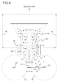
- Fig. 4 illustrates a particularly preferred embodiment of the invention.
- the crushing roll set 10 is illustrated with the grinding rolls 11 and 12, and the screw 20 rotatably mounted inside the hopper 30.
- the hopper 30 is associated with a suction chamber 60, arranged at the feed mouth 17 of the crushing roll set 10.
- the suction chamber 60 is arranged such to surround the lower section of the screw 20, and it has an inner cavity separated from the entrance chamber of the material through porous separators 61, preferably made of ceramic material.
- the inner cavity of the suction chamber 60 is in fluid communication with a vacuum pump by means of tubing 62.
- the vacuum pump appropriate sized, maintains the entrance chamber of the material in reduced pressure through the porous separators 61 which on one hand prevent fine material losses, and on the other hand protect the pump from the abrasive action of the materials.
- the air removal therefore occurs by channelling such air upward, compelling it to cross through the overlying material.
- the air suctioned by the pump is indicated by the wavy arrows P, while the small squares indicate the granular material being fed.
- the empty small squares indicate the fresh material and the solid small squares indicate the recycle material coming from the separator 40.
- Providing a suction system produces a net improvement of the working conditions of the crushing roll set (less vibrations caused by the deflagration of the air pockets present between the material grains), of the minimum attainable granulometric size, and as the following examples demonstrate, of the specific energy consumption and running cost of the plant (less wear of the rolls of the crushing roll set).
- the channelling of the air is obtained by utilising the pressure difference between the environment inside the hopper and the entrance zone of the crushing roll set, under positive pressure caused by the compression of the material, and the environment outside the suction chamber, in which the vacuum is generated.
- the crushing roll set is equipped with a lateral seal system of the rolls, schematically illustrated in figures 5 and 6 .
- Such compensated pressure lateral seal system comprises a lateral containment device 70 of the material to be ground, laterally arranged at the entrance zone 15 of the rolls, where the pressure exerted by the precompression screw 20 tends to make the material exit from the sides. Such phenomenon is greater the finer the granulometry being fed, and of course the higher the precompression exerted by the screw.
- the device 70 comprises a stationary plate 71, for example integral with the frame of the crushing roll set (not shown), and a pressure plate 72, which supports a wear plate 73 adhering to the rolls.
- the pressure plate 72 is movable along the centring guides 74 which are extended parallel to the rotation axes of the rolls, so to be able to be selectively moved away from or brought closer to the entrance zone 15.
- the movement of the pressure plate 72 is controlled by a pneumatic control 75, which operates on a pneumatic bearing 76 connecting the pressure plate 72 to the stationary plate 71.
- the pressure exerted by the containment wall 72 against the flank of the rolls, produced by the pneumatic control 75 is automatically adjusted on the force exerted by the precompression screw.
- the pneumatic control 75 is automatically adjusted on the force exerted by the precompression screw.
- adjustable thrust points 77 of the pneumatic bearing 76 are also visible, whose position with respect to the entrance zone 15 of the rolls is adjustable by means of a pre-established rotation of a movable part of the pneumatic bearing 76 (as shown in fig. 5 ).
- the pressure of the pressure plate 72 can also be previously calibrated with regard to the average size of the entering material.
- the containment device 70 therefore leads to two big advantages:
- the grinding installation is also equipped with a control system (not shown), set to monitor and control the course of the grinding, the energy efficiency of the installation, and the wear of the crushing roll set and particularly of the parts exposed to abrasive action.
- a control system not shown
- An entirely empirical expedient which nevertheless permits obtaining good functionality levels of the crushing roll set consists of adjusting the precompression value of the material in the start-compression section SI, obtained with the screw, such that the ratio between the apparent density of the exiting material with respect to that at the entrance of the rolls is approximately equal to the ratio between the distance between rolls in the outlet section SU with respect to that of start-compression SI.
- the adjustment of the pressure exerted by the piston 50 of the movable roll also permits compensating the possible variations of the average granulometry of the entering material, which depend on the inconstancy of the ratio between the raw material and the recycle material.
- control system is essentially programmed in order to maintain constant the granulometric composition of the material being fed, as well as maximise the power used by the crushing roll set.
- the system comprises a PIA (Proportional Integral Adaptive) governor prearranged for receiving a signal from a sensor positioned in the hopper, in particular a continuous level sensor whose rising or descending gradient is obtained by the PIA governor, and programmed to process the feedbacks on an inverter for adjusting the fresh material flow rate as a function of the qualitative and quantitative discontinuity of the recycle material.
- PIA Proportional Integral Adaptive
- the system is based on input signals which are a function of the vibrational response following twisting deformations on the Cardan joint of the shaft of the movable roll, which depend on the qualitative and quantitative feeding discontinuities.
- the processed signal which is the average of a high number of samplings per second, for example 500 samplings per second, serves for defining several critical frequencies, generally three, which are considered critical on the basis of experience acquired over hundreds of functioning hours and for their consequent influence on the grinding behaviour.
- an adjustment parameter is associated which intervenes in case the attention threshold is exceeded.
- the priorities in the adjustment of the various parameters are previously established based on a "recipe" which mainly takes into account the granulometry D50 being fed and the granulometry D50 of the finished product.
- the feedbacks essentially regard the above-indicated three adjustments, i.e.:
- Example A A comparison will now be illustrated between the grinding performances of crushing roll set made according to the invention (Example A) and those of a traditional tubular mill with spherical grinding bodies load (Example B). Such comparison was carried out based on identical crystalline material being fed for the two plant types.
- the plant of example A made according to the invention had a clearly lower specific energy consumption and a greater hourly production with respect to the traditional plant of example B.
- the innovative plant of example A was shown to be significantly more economical than the traditional plant of example B.
- the plant of example A has a comparatively high flexibility level. In other words, such plant lends itself:
Landscapes
- Engineering & Computer Science (AREA)
- Food Science & Technology (AREA)
- Crushing And Grinding (AREA)
Applications Claiming Priority (1)
| Application Number | Priority Date | Filing Date | Title |
|---|---|---|---|
| ITTO20070029 ITTO20070029A1 (it) | 2007-01-18 | 2007-01-18 | Cilindraia ad alta compressione per la macinazione, a livelli di finezza molto spinti, di minerali naturali e di prodotti solidi inorganici. |
Publications (1)
| Publication Number | Publication Date |
|---|---|
| EP1946844A1 true EP1946844A1 (fr) | 2008-07-23 |
Family
ID=39171365
Family Applications (1)
| Application Number | Title | Priority Date | Filing Date |
|---|---|---|---|
| EP08150367A Withdrawn EP1946844A1 (fr) | 2007-01-18 | 2008-01-17 | Jeu de broyeur à cylindres haute compression pour le broyage, aux niveaux de finesse les plus élevés, de minéraux naturels et de produits inorganiques solides |
Country Status (2)
| Country | Link |
|---|---|
| EP (1) | EP1946844A1 (fr) |
| IT (1) | ITTO20070029A1 (fr) |
Cited By (10)
| Publication number | Priority date | Publication date | Assignee | Title |
|---|---|---|---|---|
| EP2540396A1 (fr) * | 2011-06-30 | 2013-01-02 | Bühler AG | Procédé et dispositif de fabrication de farine et/ou de semoule |
| WO2015063195A1 (fr) * | 2013-10-31 | 2015-05-07 | Khd Humboldt Wedag Gmbh | Presse à rouleaux haute pression avec dégazage de la matière à broyer |
| CN106238134A (zh) * | 2016-09-08 | 2016-12-21 | 泉州惠安博派信息技术有限公司 | 一种四辊碾粉机 |
| WO2017035613A1 (fr) * | 2015-09-01 | 2017-03-09 | Vale S/A | Rouleaux de broyage pour minerai et procédé permettant d'obtenir un rendement maximal |
| WO2019159119A1 (fr) * | 2018-02-15 | 2019-08-22 | Flsmidth A/S | Mécanisme et procédé d'alimentation de dispositif de broyage |
| WO2020151222A1 (fr) * | 2019-01-25 | 2020-07-30 | 南京西普水泥工程集团有限公司 | Dispositif de mise sous pression de matériaux |
| CN112427073A (zh) * | 2020-11-19 | 2021-03-02 | 徐祥丽 | 一种食品生产原料废渣自动化处理装置 |
| US11185867B2 (en) | 2018-05-25 | 2021-11-30 | Bühler AG | Distribution metering device for a roller mill, roller mill with such a distribution metering device, method for grinding grinding stock, and roller mill comprising a switching cabinet with a cooling system |
| CN118022890A (zh) * | 2024-02-21 | 2024-05-14 | 天津水泥工业设计研究院有限公司 | 适用于生料和水泥辊压机粉磨系统的稳料仓及工作方法 |
| CN118080068A (zh) * | 2024-04-29 | 2024-05-28 | 杭州民泰(亳州)中药饮片有限公司 | 一种粒度可调的药材破碎设备及药材破碎处理方法 |
Citations (6)
| Publication number | Priority date | Publication date | Assignee | Title |
|---|---|---|---|---|
| US3114930A (en) * | 1961-03-17 | 1963-12-24 | American Cyanamid Co | Apparatus for densifying and granulating powdered materials |
| US4111626A (en) * | 1975-02-27 | 1978-09-05 | Takeda Chemical Industries, Ltd. | Powder compacting machine |
| EP0399192A1 (fr) * | 1989-05-22 | 1990-11-28 | Klöckner-Humboldt-Deutz Aktiengesellschaft | Presse à cylindres, notamment pour le broyage par pression de matériau granulé |
| EP0413155A2 (fr) * | 1989-08-16 | 1991-02-20 | Klöckner-Humboldt-Deutz Aktiengesellschaft | Installation de broyage à recyclage pour matière fragile |
| WO1993008915A1 (fr) * | 1991-11-01 | 1993-05-13 | F.L. Smidth & Co. A/S | Procede de controle de l'alimentation du materiau dans une presse a rouleaux pour l'ecrasement d'un materiau particulaire |
| US5271319A (en) * | 1990-02-05 | 1993-12-21 | Maschinenfabrik Koppern Gmbh & Co. Kg | Roll press with deaeration apparatus |
-
2007
- 2007-01-18 IT ITTO20070029 patent/ITTO20070029A1/it unknown
-
2008
- 2008-01-17 EP EP08150367A patent/EP1946844A1/fr not_active Withdrawn
Patent Citations (6)
| Publication number | Priority date | Publication date | Assignee | Title |
|---|---|---|---|---|
| US3114930A (en) * | 1961-03-17 | 1963-12-24 | American Cyanamid Co | Apparatus for densifying and granulating powdered materials |
| US4111626A (en) * | 1975-02-27 | 1978-09-05 | Takeda Chemical Industries, Ltd. | Powder compacting machine |
| EP0399192A1 (fr) * | 1989-05-22 | 1990-11-28 | Klöckner-Humboldt-Deutz Aktiengesellschaft | Presse à cylindres, notamment pour le broyage par pression de matériau granulé |
| EP0413155A2 (fr) * | 1989-08-16 | 1991-02-20 | Klöckner-Humboldt-Deutz Aktiengesellschaft | Installation de broyage à recyclage pour matière fragile |
| US5271319A (en) * | 1990-02-05 | 1993-12-21 | Maschinenfabrik Koppern Gmbh & Co. Kg | Roll press with deaeration apparatus |
| WO1993008915A1 (fr) * | 1991-11-01 | 1993-05-13 | F.L. Smidth & Co. A/S | Procede de controle de l'alimentation du materiau dans une presse a rouleaux pour l'ecrasement d'un materiau particulaire |
Cited By (10)
| Publication number | Priority date | Publication date | Assignee | Title |
|---|---|---|---|---|
| EP2540396A1 (fr) * | 2011-06-30 | 2013-01-02 | Bühler AG | Procédé et dispositif de fabrication de farine et/ou de semoule |
| WO2015063195A1 (fr) * | 2013-10-31 | 2015-05-07 | Khd Humboldt Wedag Gmbh | Presse à rouleaux haute pression avec dégazage de la matière à broyer |
| WO2017035613A1 (fr) * | 2015-09-01 | 2017-03-09 | Vale S/A | Rouleaux de broyage pour minerai et procédé permettant d'obtenir un rendement maximal |
| CN106238134A (zh) * | 2016-09-08 | 2016-12-21 | 泉州惠安博派信息技术有限公司 | 一种四辊碾粉机 |
| WO2019159119A1 (fr) * | 2018-02-15 | 2019-08-22 | Flsmidth A/S | Mécanisme et procédé d'alimentation de dispositif de broyage |
| US11185867B2 (en) | 2018-05-25 | 2021-11-30 | Bühler AG | Distribution metering device for a roller mill, roller mill with such a distribution metering device, method for grinding grinding stock, and roller mill comprising a switching cabinet with a cooling system |
| WO2020151222A1 (fr) * | 2019-01-25 | 2020-07-30 | 南京西普水泥工程集团有限公司 | Dispositif de mise sous pression de matériaux |
| CN112427073A (zh) * | 2020-11-19 | 2021-03-02 | 徐祥丽 | 一种食品生产原料废渣自动化处理装置 |
| CN118022890A (zh) * | 2024-02-21 | 2024-05-14 | 天津水泥工业设计研究院有限公司 | 适用于生料和水泥辊压机粉磨系统的稳料仓及工作方法 |
| CN118080068A (zh) * | 2024-04-29 | 2024-05-28 | 杭州民泰(亳州)中药饮片有限公司 | 一种粒度可调的药材破碎设备及药材破碎处理方法 |
Also Published As
| Publication number | Publication date |
|---|---|
| ITTO20070029A1 (it) | 2008-07-19 |
Similar Documents
| Publication | Publication Date | Title |
|---|---|---|
| EP1946844A1 (fr) | Jeu de broyeur à cylindres haute compression pour le broyage, aux niveaux de finesse les plus élevés, de minéraux naturels et de produits inorganiques solides | |
| JP5409634B2 (ja) | 鉱物性または非鉱物性材料の粉砕のための方法および装置 | |
| CN114007750B (zh) | 用于粉碎的设备、系统和方法 | |
| US10933423B2 (en) | Method and device for producing flour and/or semolina | |
| CN208260947U (zh) | 一种矿石磨粉机 | |
| CN104446077B (zh) | 废弃混凝土的分离方法、分离系统和辊压分离机 | |
| CN114273060B (zh) | 一种型砂粉碎设备 | |
| CN101966479A (zh) | 一种立辊式粉碎机 | |
| CN105435938A (zh) | 一种水泥联合粉磨系统 | |
| CN104399550A (zh) | 无极齿辊组和无极齿辊破碎机 | |
| CN108906227B (zh) | 一种立轴式破碎机及其破碎方法 | |
| CN210522589U (zh) | 双侧进料立轴多级齿刃圆锥破碎机 | |
| CN110215991A (zh) | 陶瓷湿法制粉工艺及其生产线 | |
| CN109569845A (zh) | 超细高岭土四级制粉设备和超细高岭土及其四级制粉生产工艺 | |
| CN204564237U (zh) | 一种磨粉机 | |
| CN212348950U (zh) | 一种增稠流变剂超细磨粉装置 | |
| CN204523101U (zh) | 斜摆加压外循环磨粉机 | |
| CN206184582U (zh) | 一种玻璃粉碎机 | |
| CN107999264A (zh) | 一种磨粉机给料装置 | |
| CN207981395U (zh) | 一种磨粉机给料装置 | |
| EP2471642B1 (fr) | Appareil de micronisation et procédé de micronisation de matériaux élastomères vulcanisés | |
| CN2841154Y (zh) | 工业化生产微细粉体的微细粉碎设备 | |
| CN100364670C (zh) | 工业化生产微细粉体的方法及其微细粉碎设备 | |
| CN120644280B (zh) | 一种碳分子筛造粒用稳定式粉碎装置及其造粒方法 | |
| JP2681854B2 (ja) | 粉砕設備 |
Legal Events
| Date | Code | Title | Description |
|---|---|---|---|
| PUAI | Public reference made under article 153(3) epc to a published international application that has entered the european phase |
Free format text: ORIGINAL CODE: 0009012 |
|
| AK | Designated contracting states |
Kind code of ref document: A1 Designated state(s): AT BE BG CH CY CZ DE DK EE ES FI FR GB GR HR HU IE IS IT LI LT LU LV MC MT NL NO PL PT RO SE SI SK TR |
|
| AX | Request for extension of the european patent |
Extension state: AL BA MK RS |
|
| AKX | Designation fees paid | ||
| REG | Reference to a national code |
Ref country code: DE Ref legal event code: 8566 |
|
| STAA | Information on the status of an ep patent application or granted ep patent |
Free format text: STATUS: THE APPLICATION IS DEEMED TO BE WITHDRAWN |
|
| 18D | Application deemed to be withdrawn |
Effective date: 20090124 |