EP1947255A2 - Armature pour plaques de décoffrage - Google Patents
Armature pour plaques de décoffrage Download PDFInfo
- Publication number
- EP1947255A2 EP1947255A2 EP08405012A EP08405012A EP1947255A2 EP 1947255 A2 EP1947255 A2 EP 1947255A2 EP 08405012 A EP08405012 A EP 08405012A EP 08405012 A EP08405012 A EP 08405012A EP 1947255 A2 EP1947255 A2 EP 1947255A2
- Authority
- EP
- European Patent Office
- Prior art keywords
- shuttering
- reinforcement
- plate
- wires
- wire mesh
- Prior art date
- Legal status (The legal status is an assumption and is not a legal conclusion. Google has not performed a legal analysis and makes no representation as to the accuracy of the status listed.)
- Granted
Links
Images



Classifications
-
- E—FIXED CONSTRUCTIONS
- E04—BUILDING
- E04B—GENERAL BUILDING CONSTRUCTIONS; WALLS, e.g. PARTITIONS; ROOFS; FLOORS; CEILINGS; INSULATION OR OTHER PROTECTION OF BUILDINGS
- E04B5/00—Floors; Floor construction with regard to insulation; Connections specially adapted therefor
- E04B5/16—Load-carrying floor structures wholly or partly cast or similarly formed in situ
- E04B5/32—Floor structures wholly cast in situ with or without form units or reinforcements
-
- E—FIXED CONSTRUCTIONS
- E04—BUILDING
- E04B—GENERAL BUILDING CONSTRUCTIONS; WALLS, e.g. PARTITIONS; ROOFS; FLOORS; CEILINGS; INSULATION OR OTHER PROTECTION OF BUILDINGS
- E04B5/00—Floors; Floor construction with regard to insulation; Connections specially adapted therefor
- E04B5/16—Load-carrying floor structures wholly or partly cast or similarly formed in situ
- E04B5/32—Floor structures wholly cast in situ with or without form units or reinforcements
- E04B2005/322—Floor structures wholly cast in situ with or without form units or reinforcements with permanent forms for the floor edges
-
- E—FIXED CONSTRUCTIONS
- E04—BUILDING
- E04B—GENERAL BUILDING CONSTRUCTIONS; WALLS, e.g. PARTITIONS; ROOFS; FLOORS; CEILINGS; INSULATION OR OTHER PROTECTION OF BUILDINGS
- E04B5/00—Floors; Floor construction with regard to insulation; Connections specially adapted therefor
- E04B5/16—Load-carrying floor structures wholly or partly cast or similarly formed in situ
- E04B5/32—Floor structures wholly cast in situ with or without form units or reinforcements
- E04B2005/324—Floor structures wholly cast in situ with or without form units or reinforcements with peripheral anchors or supports
-
- E—FIXED CONSTRUCTIONS
- E04—BUILDING
- E04C—STRUCTURAL ELEMENTS; BUILDING MATERIALS
- E04C5/00—Reinforcing elements, e.g. for concrete; Auxiliary elements therefor
- E04C5/01—Reinforcing elements of metal, e.g. with non-structural coatings
- E04C5/06—Reinforcing elements of metal, e.g. with non-structural coatings of high bending resistance, i.e. of essentially three-dimensional [3D] extent, e.g. lattice girders
- E04C5/0627—Three-dimensional reinforcements composed of a prefabricated reinforcing mat combined with reinforcing elements protruding out of the plane of the mat
Definitions
- the invention relates to a reinforcement for Schalalplatten, a process for their preparation and a Abschalungsplatte with such a reinforcement according to the preamble of claims 1, 7 and 8.
- ceiling edging is used to limit the volume to be filled with concrete.
- These can include, for example, formwork panels or wooden boards, which are removed after concreting the ceiling.
- lost ceiling edge shutters are, for example, prefabricated concrete slabs which are fastened to the slab formwork by suitable means. They combine with the liquid concrete of the ceiling and form the face of the ceiling tile. The concrete slabs provide the desired benefits in terms of quality and strength.
- foam boards instead of prefabricated concrete elements foam boards as a lost ceiling edge formwork and at the same time as insulating elements to prevent cold spots.
- Such plastic plates usually have a variety of supports with a small mutual distance be supported to prevent breaks or deformation due to the low intrinsic stability.
- lost formwork When using lost formwork as intermediate formwork can - depending on the type of shuttering panels - the insufficient stability and / or high installation costs and / or the large plate thickness adversely affect.
- large tensile and / or compressive forces usually act in the area of adjoining ceiling sections.
- Lost intermediate formworks should therefore be as dimensionally stable as possible.
- such networks must be kept because of the low intrinsic stability by a large number of stable frames and brackets or by a variety of additional bracing with small mutual distances.
- the nets are pierced by the protruding reinforcing bars. Often this results in larger cracks that need to be repaired, for example, with special adhesive tapes.
- the creation of such intermediate formwork is complex and expensive. Even small damages can lead to bursting or tearing of the nets when concreting.
- Shuttering devices typically include one or more planar shuttering plates 5 for laterally limiting the volume to be filled with concrete.
- a wall 1 made of concrete or bricks can be seen on a floor or ceiling slab 3 is to be concreted.
- a shuttering plate 5 also referred to as a plate, placed on the wall 1 and held by means of brackets 7, which are fastened with nails 9 on the slab formwork 11.
- the slab formwork 11 is held by supports 13 at the desired height.
- the shuttering plate 5 is designed as a lost element, ie the shuttering plate 5 connects after filling the liquid concrete for the ceiling plate 3 with the concrete and the surface 15 forms the end face of the finished ceiling panel 3.
- a formwork panel 5 is for example from EP-A1-0927796 known.
- FIG. 2 shows another Abschalungsplatte 5 with reinforcements 17 to increase the dimensional stability and protection against mechanical damage.
- the reinforcements 17 may include planar steel mesh with relatively large rod cross-sections or meshes of aramid or coated glass fibers.
- flat reinforcing mesh are completely embedded in a lightweight construction material such as polystyrene or another foamed mass of plastic or sand and additives.
- the reinforcement 17 is invisible and has no influence on the surface condition of the panel. In intervals of the reinforcement 17 may be provided with small distances vertically extending holes or channels 19, which allow insertion of the headband 7 from below and ensure the same.
- the shuttering plate 5 may have a smaller thickness in the lower and possibly also in the upper region, so that the stirrups 7, as in FIG FIG. 1 represented, leave the shuttering plate 5 side and can be aligned exactly horizontal.
- the reinforcement 17 is formed as a multi-folded, perforated reinforcing plate.
- This can for example be made of sheet metal by bending operations or of an extruded plastic profile and is not or only partially, ie not completely, embedded in the interior of the plate 5.
- two angled portions 23 overhang the inner surface 25 of the reinforcing plate. These angled portions 23 are with aligned holes 27 provided, through which the vertical legs of the headband 7 are inserted from below.
- aligned holes 27 In parallel to the inner plate surface ( FIG. 1 ) extending areas adjacent to the sections 23 openings 29 are mounted in the reinforcing plate. These cause a close connection with the plastic compound or the lightweight building material (matrix) on both sides of the reinforcing plate.
- shuttering panels 5 can also be designed as reusable panels which - like the ceiling formwork 11 - are treated with an anti-adhesive agent prior to concreting and are removed again after the concrete has set.
- FIG. 4 shows an example of a cross section in the region of an intermediate formwork for creating a ceiling portion, wherein the shuttering panels 5 as in the ceiling edge Abschalung in FIG. 1 are formed as lost plates.
- such intermediate formwork requires that reinforcing elements 31 (FIG. FIG. 5 ) such as reinforcing bars of the work part to be created, the intermediate formwork can penetrate, so as to connect the individual sections of the work piece, which are consecutively concreted together.
- reinforcing elements 31 such as reinforcing bars of the work part to be created
- the intermediate formwork can penetrate, so as to connect the individual sections of the work piece, which are consecutively concreted together.
- weak points or thin spots or predetermined breaking points for example in the form of recesses 33 or perforations, are formed in the shuttering panel 5.
- Shuttering slabs 5 according to the invention for lost intermediate formworks comprise hard, inelastic and incompressible or pressure-resistant materials, so that no deformations occur when external forces, such as occur in the area of abutting ceiling sections, occur.
- FIG. 5 shows a perspective view of a possible embodiment of such Abschalungsplatte 5, wherein the weak points or predetermined breaking points are formed as a pan-shaped recesses 33 on one side or both sides in the surface or the opposite main sides 34 of the Abschalungsplatte 5.
- Such shuttering plates 5 can be attached to the reinforcements 31 by means of one or both sides of the shuttering plates 5 on the reinforcements 31 or snap-on clamping or holding elements 41, as shown in FIG FIG. 5 is shown as an example.
- Such Schalalplatten 5 can be relatively thin and still stable.
- shuttering plates 5 can be made thin and stable.
- protruding reinforcing sections can be provided from the plate surface, which enable a simple and cost-effective fastening of the shuttering plates 5 by means of holding clips 7.
- the reinforcements 17 of the invention can also - analogously to FIG. 2 - Just and completely integrated into the shuttering plate 5.
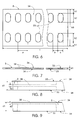
- FIG. 6 shows one of the two main sides 34 of the Abschalungsplatte. 5 FIG.
- FIG. 7 shows an end view of the Abschalungsplatte 5 and FIG. 8 a detail thereof in the region of the recesses 33.
- the recesses 33 are located on both main sides 34 directly opposite. You can, for example, at regular intervals a ( Fig. 6 ) may be arranged in two parallel rows along the longitudinal sides of the shuttering plate 5. In the case of a multiple use of such shuttering plate 5, this can be due to the slightly conical edges of the recesses 33 after the Hardening the concrete relatively easily separated from the created section of the workpiece.
- the cup-shaped depressions 33 with a conical edge are formed only on one of the main sides 34.
- the wire mesh reinforcements according to the invention can be manufactured and / or adapted according to the requirements of different shuttering plates 5, as described by way of example below.
- the shuttering plates 5 can be made in large lengths 1 of several meters and usually shortened when required for example by sawing or be cut to length. Lengths in the range from about 2 m to about 4 m, for example 2.8 m, are advantageous.
- Adjacent depressions 33 in a row are offset from one another by a distance a of preferably approximately 50 mm. For oval wells 33 having a width c (FIG. FIG.
- the distance h1 of the recesses 33 from the associated edges of the shuttering panel 5 is preferably about 20mm.
- the arrangement of the recesses 33 corresponds to possible arrangements of reinforcements 31 which are intended to penetrate the intermediate shuttering.
- An integer multiple of the offset or distance a of two adjacent depressions 33 preferably corresponds to the average distance between two adjacent reinforcing bars.
- the Abschalungsplatten 5 can also be formed with bends and corners. With such elements intermediate formwork can be made with any shape.
- the shuttering plates 5 can be used with appropriate training both as shuttering elements for intermediate formwork as well as for Randabschalieux.
- the surface of the shuttering plate 5 may be formed on one and / or on both main sides 34 smooth and / or rough.
- a shuttering plate 5 as in the FIGS. 5 to 9 can be, for example, mainly or completely made of compressed wood, concrete, plastic or cardboard.
- Sheathing panels 5 of fiber concrete are preferably cast in a horizontally lying mold (not shown) with frustoconical elevations, these elevations being coated only with one thin layer 36 each having a thickness d2 of, for example, 1 mm or less to about 5 mm of the cast material.
- weak points are made of the same material as the remaining areas of the shuttering plate 5.
- the weak points are not in the interior of the plate 5, but on the outside, arranged on one of the main sides 34 flush with the surface in this embodiment.
- weak points may also be limited by perforations which are arranged along a closed line and form the edge of the weak points, wherein the holes comprise, for example, a diameter of about 1 mm to 3 mm and adjacent holes each have a diameter of 1 mm Include spacing of the same magnitude (no representation).
- Such perforations can basically be formed both in lost and in reusable Abschalplatten 5 for edge or intermediate formworks of any thickness, regardless of whether these with or without holes 19 for retaining bracket 7 (FIG. Figures 1 and 2 ) and / or are formed with not or partially from the Abschalplatte 5 outstanding reinforcement 17 or without reinforcement 17.
- perforations can also be formed in pressed, foamed or otherwise manufactured plates. For plates with holes 19 and recesses 33 and / or perforations may be provided which intersect or penetrate the holes 19. An assembly of such Abschalungsplatten 5 by means of brackets 7 or angles, which are each introduced with one of its legs in a respective bore 19, is thus easily possible.
- the thickness or thickness d1 of the Abschalplatten 5 may, for example, in the range of about 6mm to about 50mm.
- brittle material such as fiber concrete
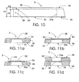
- the shuttering plate 5 can also be made of two layers, namely a main plate 38 (FIG. FIG.
- the thickness d1 of the Abschalungsplatte 5 substantially the sum of the thicknesses d2 of the main plate 38 and d3 of the further plate 40 corresponds.
- the main plate 38 in this case comprises recesses 33a in the region of the weak points. These are unilaterally covered by the further plate 40 and thus form the recesses 33 in the Abschalungsplatte 5.
- the thin layer 36 and the thin further plate 40 can be made of the same material as the main plate 38 and glued to this example, anchored or in be connected in any other way. Alternatively, the plate 40 or the thin layer 36 may also be made of a different material or comprise other materials than the main plate 38.
- thin layers 36 for example, from woven fabrics, films, tiles, cardboard, wood materials and the like, and to anchor them before or during the curing of the main plate 38 at this.
- the thin layer 36 can for this example, angled tongues or pins 43 (FIG. Fig. 11d ) or other areas immersed in the casting material.
- thin layers 36 can also be glued, for example or connected to main panels 38 by other joining techniques.
- the weak points are formed as thin spots in this one layer.
- the cup-like weak spots may e.g. be made by truncated cone-like cones in the mold.
- thin spots can be used e.g. for pressed boards of wood or other materials by mechanical reworking of these boards, e.g. by milling, be formed.
- the material of such monolayer Abschalungsplatten 5 is in the region of the weak points identical to the base material or the matrix of the remaining areas of Abschalungsplatte 5.
- the weak points are made of the same material or the same materials as the immediately adjacent to the weak points areas of Abschalungsplatte 5th
- the two plates 38, 40 may be made of the same or alternatively of different materials.
- the material in the region of the weak points is identical to the material of the regions of the plate 40 which are directly adjacent to the weak points, or preferably the entire plate 40.
- the material composition in the region of the weak points is thus identical to that of the adjoining areas of the shuttering panel 5, at least on one of the main sides 34.
- FIGS. 11a to 11d show detailed cross sections in the region of a weak point for some possible embodiments of the shuttering plate 5.
- the shuttering plate 5 comprises only one layer, namely the main plate 38 made of fiber cement or other suitable material.
- the weak points are formed by pan-like recesses 33 as brittle thin layers 36 in the integrally cast main plate 38.
- Such depressions 33 can, as in FIG. 11a one-sided or according to FIG. 8 from both Main pages 34 ago be inserted into the Abschalungsplatte 5.
- the thin layer 36 may therefore be arranged flush with respect to the two main sides 34, for example, or in any other position.
- FIG. 11b Shuttering plate 5 shown comprises two layers, namely the main plate 38 with the recesses 33 and the thin further plate 40 which is connected to the main plate 38 and completely covers them. Those areas of the further plate 40, which cover the recesses 33a like a membrane, form the weak points of the shuttering plate 5.
- the recesses 33a can be formed with conical or vertical boundary walls.
- FIG. 11c shows a further variant of the Abschalungsplatte 5, wherein compared to FIG.
- each thin layer 36 extends beyond the edge of the respectively associated recess 33a or overlaps this edge and is in or on the region adjacent to the recess 33a the shuttering plate 5 is held or fixed.
- the thin layers 36 thus only cover part of the respective main side 34.
- Each of the thin layers 36 may comprise, for example, one or more pins 43 projecting into the main plate 38 or other holding elements for anchoring in the main plate 38.
- two main plates 38 are connected to a shuttering plate 5, wherein one of the main plates 38 includes recesses 33a and the other main plate 38 includes recesses 33 defined by thin layers 36.
- the recesses 33a and the depressions 33 lie directly opposite one another and preferably have the same or similar shape and size in the region of the thin layers 36.
- a common feature of these embodiments is that at least on one of the main sides 34 of the Abschalungsplatte 5, the material or the material composition in the weak points is the same as in the immediately adjacent to the weak points areas of Abschalungsplatte. 5
- the shuttering plate 5 comprises a reinforcement 17 made of a wire mesh 45.
- reinforcements 17 may be formed in one piece his or her several unconnected parts.
- reinforcements 17 may comprise, for example, flat or multiply curved perforated sheets, perforated sheets or grid structures.
- free spaces or holes or openings 29 are in these reinforcements ( Fig. 3 ) educated.
- Subregions of the reinforcement 17 preferably project beyond one or both of the main sides 34. They may, for example (as in FIG FIG. 3 shown) angled portions 23 with holes 27 for attaching retaining clips 7 include.
- the reinforcing structures can be connected to the shuttering plate 5, for example by gluing or other joining techniques on the surface or one of the main sides 34.
- the reinforcing structures are preferably at least partially embedded in these shuttering plates 5.
- the reinforcement 17 can be inserted or immersed in the casting compound with any desired predeterminable immersion depth. By hardening the casting compound, the reinforcement 17 is fixed to the Schalalplatte 5 connected.
- the immersion depth preferably corresponds to approximately half the thickness d1 of the plate 5.
- one or both layers or layers with a reinforcement 17 can be reinforced in an analogous manner even in the case of two-layer shuttering plates 5.
- two or more vertically aligned shapes may be formed side by side, thereby enabling simultaneous filling of multiple shapes.
- Reinforcements 17 according to the invention prove to be particularly advantageous in the form of multiply bent or deformed wire meshes 45.
- FIG. 12 shows such a wire mesh 45 with at all or at least a portion of the intersection welded together straight wires 47 and multiple bent and / or kinked or deformed transverse wires 49, which may be smooth or structured and a diameter in the order of about 0.5mm to about 6mm or corresponding cross-sectional areas in the order of about 0.2mm 2 to about 30mm 2 have.
- Longitudinal wires 47 and transverse wires 49 preferably include a right angle.
- the diameters of the wires are smaller than the smallest diameter customary in rebars, eg 4mm, 5mm or 6mm.
- transverse wires 49 with small diameters in the Size of 1.5mm to 2mm in combination with longitudinal wires 47 with slightly larger diameters of eg 2.5mm to 3mm.
- Such grids can be made by simultaneously rolling several (eg five) to many (eg fifty) transverse wires 49 and periodically welding together with longitudinal wires 47 and then forming the transverse wires 49.
- several or many longitudinal wires 47 could be handled simultaneously in an analogous manner and periodically connected to transverse wires 49.
- the welding of a longitudinal wire 47 with a plurality of transverse wires 49 can be carried out sequentially or preferably simultaneously.
- the initially planar wire mesh 45 or its transverse wires 49 are preferably reshaped such that wave-shaped regions 51 protrude from the lattice plane.
- each transverse wire 49 is concavely curved and each transitions into a linear section 55 lying in the lattice plane.
- the transverse wires 49 are connected analogously to the wave crests by longitudinal wires 47 on the upper side of the grating.
- Each two adjacent longitudinal wires 47 and each two adjacent transverse wires 49 thus frame in the lattice plane arranged grid openings 57.
- Such grid openings 57 may, for example square or rectangular and preferably have side lengths in the range of about 2cm to about 10cm.
- the longitudinal wires 47 and / or the transverse wires 49 are soft or not hardened or low in carbon. Their tensile strength is typically in the range of about 300 N / mm 2 to about 500 N / mm 2 or to about 650 N / mm 2 .
- welding may cause unwanted distortion or distortion of the grid due to stress, or stresses may hinder or render impossible deformation in the desired manner.
- the shape of the grid can be maintained.
- such gratings can be formed, for example, by means of known forming techniques in the desired manner.
- Conventional reinforcing steel bars are not suitable for the inventive grid due to the available diameter and hardness.
- wires such as those used in the manufacture of garden fences, are suitable for the production of the welded meshes according to the invention.
- the wires can be tempered eg by galvanizing and protected against oxidation. Such a remuneration serves primarily to improve the visual appearance and is not absolutely necessary.
- the wire mesh 45 may be configured in other ways. For example, those of the longitudinal wires 47 and the transverse wires 49 enclosed angle arbitrary values in the range of eg 30 ° to eg 150 ° have (no representation).
- the wire mesh 45 can be left just in accordance with the respective requirements or be converted in any way to a three-dimensional structure.
- the shape can be chosen so that thereby increases the stability or dimensional stability of the wire grid 45 and / or the wire mesh 45 are given other properties.
- one or more of a main plane outstanding portions of the wire grid 45 may be formed as a fastening means and formed, for example, for receiving retaining clips 7.
- Such receptacles are preferably designed as guides, in each of which a leg of a retaining clip 7 can be inserted and held without play or with only a small amount of play in a defined position.
- the guides can be formed, for example, alone by the arrangement of the wires of the wire grid 45 in uniform or non-uniform intervals.
- guides can also be formed by a deformation of longitudinal and / or transverse wires in more than one dimension or spatial direction (not shown).
- the peaks or peaks 53 of two adjacent transverse wires 49 are additionally deformed in the direction of the longitudinal wires 47 against each other, so claw-like or claw-like Shooting or guides are designed for insertion of retaining bracket legs.
- This is also associated with a deformation of the longitudinal wires 47 and a reduction of the original distance of the adjacent, claw-like deformed transverse wires 49.
- the opening cross sections of the headband receptacles are not circular, but for example, approximately or partially elliptical or rectangular shaped.
- retaining bar legs with rectangular cross-section eg 17mm x 10mm
- a retaining clip 7 As soon as a retaining clip 7 is inserted into the receptacle up to the desired end position, it can be moved about 90 ° into its definitive position (as well as in FIG FIG. 3 shown), where it rests against the deformed transverse wires and is held in this position.
- recesses formed in this way can also easily support bracket legs inserted with laterally outstanding retaining fingers or locking elements and locked with the shuttering plate 5 and the reinforcement 17, wedged, hooked or connected in any other way.
- the guides for receiving the headband legs may include, in addition to the wires of the wire screen 45 also other parts, such as the upper main page 34 of in FIG. 13 Shuttering plate 5 shown.
- FIG. 13 shows a shuttering panel 5 with a wireframe reinforcement seen from one of the narrow end faces.
- the transverse wires 49 project beyond the upper main side 34 of the shuttering plate 5 in the region of two peaks.
- the there connected to the transverse wires 49 longitudinal wires 47 are completely outside of the preferably integrally molded main plate 38.
- the recesses 33 which form the weak points of Abschalungsplatte 5, are arranged in the region of the grid openings 57, wherein the legs of two longitudinal wires 47 and two transverse wires 49 are framed, but not directly adjacent to these.
- the plate thickness is so low that these areas can be broken completely or partially, for example, by striking with a hammer.
- Abschalungsplatte 5 as an intermediate formwork reinforcements 31 can easily penetrate the Abschalungsplatte 5 in the area of weak points when the Abschalungsplatte 5 is pressed or beaten against the ends of the protruding reinforcing rods (or vice versa).
- the disc-like vulnerability is completely broken out of the shuttering plate 5 or penetrate the reinforcing rods - similar to a nail that is taken - the weak points, without the entire Slice out the vulnerability.
- Shuttering plates 5 may also be curved and / or comprise a plurality of sections or sections, each two adjoining sections each enclosing a fixed or - in the case of hinge-like sections - a variable angle.
Landscapes
- Engineering & Computer Science (AREA)
- Architecture (AREA)
- Physics & Mathematics (AREA)
- Electromagnetism (AREA)
- Civil Engineering (AREA)
- Structural Engineering (AREA)
- Forms Removed On Construction Sites Or Auxiliary Members Thereof (AREA)
- Moulds, Cores, Or Mandrels (AREA)
- Reinforcement Elements For Buildings (AREA)
Applications Claiming Priority (1)
| Application Number | Priority Date | Filing Date | Title |
|---|---|---|---|
| CH742007 | 2007-01-17 |
Publications (3)
| Publication Number | Publication Date |
|---|---|
| EP1947255A2 true EP1947255A2 (fr) | 2008-07-23 |
| EP1947255A3 EP1947255A3 (fr) | 2013-07-03 |
| EP1947255B1 EP1947255B1 (fr) | 2019-03-13 |
Family
ID=39282897
Family Applications (2)
| Application Number | Title | Priority Date | Filing Date |
|---|---|---|---|
| EP08405012.9A Active EP1947255B1 (fr) | 2007-01-17 | 2008-01-17 | Armature pour plaques de décoffrage |
| EP08405014.5A Active EP1947257B1 (fr) | 2007-01-17 | 2008-01-17 | Elément de décoffrage |
Family Applications After (1)
| Application Number | Title | Priority Date | Filing Date |
|---|---|---|---|
| EP08405014.5A Active EP1947257B1 (fr) | 2007-01-17 | 2008-01-17 | Elément de décoffrage |
Country Status (1)
| Country | Link |
|---|---|
| EP (2) | EP1947255B1 (fr) |
Cited By (1)
| Publication number | Priority date | Publication date | Assignee | Title |
|---|---|---|---|---|
| EP2103752A1 (fr) * | 2008-03-20 | 2009-09-23 | Fensterfabrik Albisrieden Ag | Couverture |
Families Citing this family (1)
| Publication number | Priority date | Publication date | Assignee | Title |
|---|---|---|---|---|
| CN109518860B (zh) * | 2018-12-13 | 2024-05-03 | 无锡佳尔旺环保科技有限公司 | 可拆卸自承式桁架复合材料楼承板 |
Citations (2)
| Publication number | Priority date | Publication date | Assignee | Title |
|---|---|---|---|---|
| EP0927796A1 (fr) | 1997-12-30 | 1999-07-07 | System Albanese | Panneau et système de coffrage |
| EP1327732A1 (fr) | 2001-12-24 | 2003-07-16 | System Albanese | Coffrage de rive pour dalles en béton |
Family Cites Families (14)
| Publication number | Priority date | Publication date | Assignee | Title |
|---|---|---|---|---|
| AU3981068A (en) * | 1969-06-27 | 1971-01-07 | Improvements in and relating to nosings | |
| GB1500731A (en) * | 1976-01-06 | 1978-02-08 | Laing & Son Ltd John | Joint member for a concrete slab or paving |
| GB1524824A (en) * | 1976-07-15 | 1978-09-13 | Gkn Reinforcements Ltd | Metal mesh |
| CH646751A5 (de) * | 1980-05-01 | 1984-12-14 | Pawe Ag | Verwendung von aus streckmetall oder aus blech mit aufgerauhter oberflaeche bestehenden profilelementen bei der betonierung eines bauwerkes. |
| DE8325086U1 (de) * | 1983-09-01 | 1983-12-22 | Bauer, Anton, 7107 Neckarsulm | Kragplatte fuer bauwerke |
| GB8826206D0 (en) * | 1988-11-09 | 1988-12-14 | Cliffstone Products Ltd | Concrete screed rails |
| EP0519146B1 (fr) * | 1991-06-17 | 1995-01-18 | Brefeba N.V. | Coffrage d'about |
| DE9400337U1 (de) * | 1994-01-11 | 1994-02-24 | Eberle, Bernd, 72661 Grafenberg | Deckenrandschalungselement |
| DE29907609U1 (de) * | 1999-04-29 | 2000-09-07 | Dausend, Hans-Werner, 42279 Wuppertal | Schalungssystem |
| ATE531864T1 (de) * | 2002-11-21 | 2011-11-15 | Ankaba Ag | Abschalungsplatte sowie verfahren zu ihrer herstellung und befestigung |
| US6874288B1 (en) * | 2003-02-03 | 2005-04-05 | Crete-Form, Inc | Concrete deck depression form system |
| DE20311707U1 (de) * | 2003-07-30 | 2003-10-23 | Döllen, Heinz von, 58239 Schwerte | Beim Betonieren einzusetzendes, bleibendes (verlorenes) Schalelement und damit realisierbare Schalungen |
| DE20318236U1 (de) * | 2003-11-25 | 2004-02-19 | Msl Mathieu Schalungssysteme Und Lufttechnische Komponenten Gmbh | Decken- oder Sohlenrandschalung |
| GB0409216D0 (en) * | 2004-04-24 | 2004-05-26 | Metaform Ltd | Multi purpose screed rail, formwork and joint protection mechanism |
-
2008
- 2008-01-17 EP EP08405012.9A patent/EP1947255B1/fr active Active
- 2008-01-17 EP EP08405014.5A patent/EP1947257B1/fr active Active
Patent Citations (2)
| Publication number | Priority date | Publication date | Assignee | Title |
|---|---|---|---|---|
| EP0927796A1 (fr) | 1997-12-30 | 1999-07-07 | System Albanese | Panneau et système de coffrage |
| EP1327732A1 (fr) | 2001-12-24 | 2003-07-16 | System Albanese | Coffrage de rive pour dalles en béton |
Cited By (2)
| Publication number | Priority date | Publication date | Assignee | Title |
|---|---|---|---|---|
| EP2103752A1 (fr) * | 2008-03-20 | 2009-09-23 | Fensterfabrik Albisrieden Ag | Couverture |
| WO2009115286A1 (fr) * | 2008-03-20 | 2009-09-24 | Fensterfabrik Albisrieden Ag | Dalle |
Also Published As
| Publication number | Publication date |
|---|---|
| EP1947257B1 (fr) | 2019-03-13 |
| EP1947255B1 (fr) | 2019-03-13 |
| EP1947257A3 (fr) | 2013-07-03 |
| EP1947257A2 (fr) | 2008-07-23 |
| EP1947255A3 (fr) | 2013-07-03 |
Similar Documents
| Publication | Publication Date | Title |
|---|---|---|
| DE69128482T2 (de) | Plattenmodul aus geschäumtem kunststoff mit versetzten t-förmigen längskanälen für hölzerne stützen | |
| EP1568827A1 (fr) | Procédé et moyen de fabrication de pièces en béton | |
| EP2963205B1 (fr) | Dispositif de coffrage | |
| DE69711658T2 (de) | Selbsttragendes bauelement aus expandiertem plastik, insbesondere für die herstellung von bodenplatten und gebäudewänden im allgemeinen | |
| DE202004004965U1 (de) | Schalungselement | |
| EP0164330B1 (fr) | Plancher en béton armé | |
| EP1947255B1 (fr) | Armature pour plaques de décoffrage | |
| EP1947256B1 (fr) | Dispositif de coffrage | |
| EP1842984B1 (fr) | Plaque de coffrage profilée de bordure de dalle en béton | |
| EP0299226A2 (fr) | Coffrage pour la réalisation d'éléments de construction en béton | |
| DE4424941A1 (de) | Verbundschalungssystem | |
| DE19643800C2 (de) | Wandschalung | |
| EP1972734A1 (fr) | Corps de fixation pour un panneau isolant | |
| DE19637379A1 (de) | Verfahren und Vorrichtung zum Herstellen von Bauelementen sowie danach hergestellte Bauelemente | |
| DE19636828C2 (de) | Verfahren und Bauelement zur Herstellung von Bauwerksteilen | |
| EP2175079B1 (fr) | Procédé de formation d'une armature d'angle résistante à la flexion pour la construction en béton armé, élément d'armature et armature d'angle résistante à la flexion | |
| DE19625514C2 (de) | Schalenbauteil für Wände oder Decken und Verfahren zur Herstellung des Schalenbauteils | |
| EP1987211A1 (fr) | Element de construction | |
| AT412295B (de) | Hohlwand - verbindungsträger für vollflächiges aufbringen von wärmedämmplatten auf der innenseiteder verlorenen schalung | |
| CH712684B1 (de) | Raumzellenelement zum modularen Aufbau eines Gebäudes | |
| DE102006047968A1 (de) | Gestützte Schalungsplatte | |
| DE102011002241A1 (de) | Bautechnisches Schalungssystem | |
| DE7810413U1 (de) | Schalkoerper | |
| DE2721767A1 (de) | Vorgefertigtes schalungselement | |
| DE2148145A1 (de) | Verfahren zum Herstellen einer Bau platte, insbesondere Wand oder Decken platte |
Legal Events
| Date | Code | Title | Description |
|---|---|---|---|
| PUAI | Public reference made under article 153(3) epc to a published international application that has entered the european phase |
Free format text: ORIGINAL CODE: 0009012 |
|
| AK | Designated contracting states |
Kind code of ref document: A2 Designated state(s): AT BE BG CH CY CZ DE DK EE ES FI FR GB GR HR HU IE IS IT LI LT LU LV MC MT NL NO PL PT RO SE SI SK TR |
|
| AX | Request for extension of the european patent |
Extension state: AL BA MK RS |
|
| PUAL | Search report despatched |
Free format text: ORIGINAL CODE: 0009013 |
|
| AK | Designated contracting states |
Kind code of ref document: A3 Designated state(s): AT BE BG CH CY CZ DE DK EE ES FI FR GB GR HR HU IE IS IT LI LT LU LV MC MT NL NO PL PT RO SE SI SK TR |
|
| AX | Request for extension of the european patent |
Extension state: AL BA MK RS |
|
| RIC1 | Information provided on ipc code assigned before grant |
Ipc: E04B 5/32 20060101AFI20130530BHEP Ipc: E04C 5/06 20060101ALI20130530BHEP |
|
| 17P | Request for examination filed |
Effective date: 20130826 |
|
| RBV | Designated contracting states (corrected) |
Designated state(s): AT BE BG CH CY CZ DE DK EE ES FI FR GB GR HR HU IE IS IT LI LT LU LV MC MT NL NO PL PT RO SE SI SK TR |
|
| AKX | Designation fees paid |
Designated state(s): AT BE BG CH CY CZ DE DK EE ES FI FR GB GR HR HU IE IS IT LI LT LU LV MC MT NL NO PL PT RO SE SI SK TR |
|
| 17Q | First examination report despatched |
Effective date: 20160830 |
|
| STAA | Information on the status of an ep patent application or granted ep patent |
Free format text: STATUS: EXAMINATION IS IN PROGRESS |
|
| GRAP | Despatch of communication of intention to grant a patent |
Free format text: ORIGINAL CODE: EPIDOSNIGR1 |
|
| STAA | Information on the status of an ep patent application or granted ep patent |
Free format text: STATUS: GRANT OF PATENT IS INTENDED |
|
| INTG | Intention to grant announced |
Effective date: 20181022 |
|
| GRAS | Grant fee paid |
Free format text: ORIGINAL CODE: EPIDOSNIGR3 |
|
| GRAA | (expected) grant |
Free format text: ORIGINAL CODE: 0009210 |
|
| STAA | Information on the status of an ep patent application or granted ep patent |
Free format text: STATUS: THE PATENT HAS BEEN GRANTED |
|
| AK | Designated contracting states |
Kind code of ref document: B1 Designated state(s): AT BE BG CH CY CZ DE DK EE ES FI FR GB GR HR HU IE IS IT LI LT LU LV MC MT NL NO PL PT RO SE SI SK TR |
|
| REG | Reference to a national code |
Ref country code: GB Ref legal event code: FG4D Free format text: NOT ENGLISH |
|
| REG | Reference to a national code |
Ref country code: CH Ref legal event code: EP Ref country code: AT Ref legal event code: REF Ref document number: 1107851 Country of ref document: AT Kind code of ref document: T Effective date: 20190315 |
|
| REG | Reference to a national code |
Ref country code: DE Ref legal event code: R096 Ref document number: 502008016643 Country of ref document: DE |
|
| REG | Reference to a national code |
Ref country code: IE Ref legal event code: FG4D Free format text: LANGUAGE OF EP DOCUMENT: GERMAN |
|
| REG | Reference to a national code |
Ref country code: CH Ref legal event code: NV Representative=s name: GACHNANG AG PATENTANWAELTE, CH |
|
| REG | Reference to a national code |
Ref country code: NL Ref legal event code: MP Effective date: 20190313 |
|
| REG | Reference to a national code |
Ref country code: LT Ref legal event code: MG4D |
|
| PG25 | Lapsed in a contracting state [announced via postgrant information from national office to epo] |
Ref country code: FI Free format text: LAPSE BECAUSE OF FAILURE TO SUBMIT A TRANSLATION OF THE DESCRIPTION OR TO PAY THE FEE WITHIN THE PRESCRIBED TIME-LIMIT Effective date: 20190313 Ref country code: NO Free format text: LAPSE BECAUSE OF FAILURE TO SUBMIT A TRANSLATION OF THE DESCRIPTION OR TO PAY THE FEE WITHIN THE PRESCRIBED TIME-LIMIT Effective date: 20190613 Ref country code: SE Free format text: LAPSE BECAUSE OF FAILURE TO SUBMIT A TRANSLATION OF THE DESCRIPTION OR TO PAY THE FEE WITHIN THE PRESCRIBED TIME-LIMIT Effective date: 20190313 Ref country code: LT Free format text: LAPSE BECAUSE OF FAILURE TO SUBMIT A TRANSLATION OF THE DESCRIPTION OR TO PAY THE FEE WITHIN THE PRESCRIBED TIME-LIMIT Effective date: 20190313 |
|
| PG25 | Lapsed in a contracting state [announced via postgrant information from national office to epo] |
Ref country code: LV Free format text: LAPSE BECAUSE OF FAILURE TO SUBMIT A TRANSLATION OF THE DESCRIPTION OR TO PAY THE FEE WITHIN THE PRESCRIBED TIME-LIMIT Effective date: 20190313 Ref country code: NL Free format text: LAPSE BECAUSE OF FAILURE TO SUBMIT A TRANSLATION OF THE DESCRIPTION OR TO PAY THE FEE WITHIN THE PRESCRIBED TIME-LIMIT Effective date: 20190313 Ref country code: HR Free format text: LAPSE BECAUSE OF FAILURE TO SUBMIT A TRANSLATION OF THE DESCRIPTION OR TO PAY THE FEE WITHIN THE PRESCRIBED TIME-LIMIT Effective date: 20190313 Ref country code: GR Free format text: LAPSE BECAUSE OF FAILURE TO SUBMIT A TRANSLATION OF THE DESCRIPTION OR TO PAY THE FEE WITHIN THE PRESCRIBED TIME-LIMIT Effective date: 20190614 Ref country code: BG Free format text: LAPSE BECAUSE OF FAILURE TO SUBMIT A TRANSLATION OF THE DESCRIPTION OR TO PAY THE FEE WITHIN THE PRESCRIBED TIME-LIMIT Effective date: 20190613 |
|
| PG25 | Lapsed in a contracting state [announced via postgrant information from national office to epo] |
Ref country code: ES Free format text: LAPSE BECAUSE OF FAILURE TO SUBMIT A TRANSLATION OF THE DESCRIPTION OR TO PAY THE FEE WITHIN THE PRESCRIBED TIME-LIMIT Effective date: 20190313 Ref country code: EE Free format text: LAPSE BECAUSE OF FAILURE TO SUBMIT A TRANSLATION OF THE DESCRIPTION OR TO PAY THE FEE WITHIN THE PRESCRIBED TIME-LIMIT Effective date: 20190313 Ref country code: CZ Free format text: LAPSE BECAUSE OF FAILURE TO SUBMIT A TRANSLATION OF THE DESCRIPTION OR TO PAY THE FEE WITHIN THE PRESCRIBED TIME-LIMIT Effective date: 20190313 Ref country code: IT Free format text: LAPSE BECAUSE OF FAILURE TO SUBMIT A TRANSLATION OF THE DESCRIPTION OR TO PAY THE FEE WITHIN THE PRESCRIBED TIME-LIMIT Effective date: 20190313 Ref country code: RO Free format text: LAPSE BECAUSE OF FAILURE TO SUBMIT A TRANSLATION OF THE DESCRIPTION OR TO PAY THE FEE WITHIN THE PRESCRIBED TIME-LIMIT Effective date: 20190313 Ref country code: PT Free format text: LAPSE BECAUSE OF FAILURE TO SUBMIT A TRANSLATION OF THE DESCRIPTION OR TO PAY THE FEE WITHIN THE PRESCRIBED TIME-LIMIT Effective date: 20190713 Ref country code: SK Free format text: LAPSE BECAUSE OF FAILURE TO SUBMIT A TRANSLATION OF THE DESCRIPTION OR TO PAY THE FEE WITHIN THE PRESCRIBED TIME-LIMIT Effective date: 20190313 |
|
| PG25 | Lapsed in a contracting state [announced via postgrant information from national office to epo] |
Ref country code: PL Free format text: LAPSE BECAUSE OF FAILURE TO SUBMIT A TRANSLATION OF THE DESCRIPTION OR TO PAY THE FEE WITHIN THE PRESCRIBED TIME-LIMIT Effective date: 20190313 |
|
| REG | Reference to a national code |
Ref country code: DE Ref legal event code: R097 Ref document number: 502008016643 Country of ref document: DE |
|
| PG25 | Lapsed in a contracting state [announced via postgrant information from national office to epo] |
Ref country code: IS Free format text: LAPSE BECAUSE OF FAILURE TO SUBMIT A TRANSLATION OF THE DESCRIPTION OR TO PAY THE FEE WITHIN THE PRESCRIBED TIME-LIMIT Effective date: 20190713 |
|
| PLBE | No opposition filed within time limit |
Free format text: ORIGINAL CODE: 0009261 |
|
| STAA | Information on the status of an ep patent application or granted ep patent |
Free format text: STATUS: NO OPPOSITION FILED WITHIN TIME LIMIT |
|
| PG25 | Lapsed in a contracting state [announced via postgrant information from national office to epo] |
Ref country code: DK Free format text: LAPSE BECAUSE OF FAILURE TO SUBMIT A TRANSLATION OF THE DESCRIPTION OR TO PAY THE FEE WITHIN THE PRESCRIBED TIME-LIMIT Effective date: 20190313 |
|
| 26N | No opposition filed |
Effective date: 20191216 |
|
| PG25 | Lapsed in a contracting state [announced via postgrant information from national office to epo] |
Ref country code: SI Free format text: LAPSE BECAUSE OF FAILURE TO SUBMIT A TRANSLATION OF THE DESCRIPTION OR TO PAY THE FEE WITHIN THE PRESCRIBED TIME-LIMIT Effective date: 20190313 |
|
| PG25 | Lapsed in a contracting state [announced via postgrant information from national office to epo] |
Ref country code: TR Free format text: LAPSE BECAUSE OF FAILURE TO SUBMIT A TRANSLATION OF THE DESCRIPTION OR TO PAY THE FEE WITHIN THE PRESCRIBED TIME-LIMIT Effective date: 20190313 |
|
| PG25 | Lapsed in a contracting state [announced via postgrant information from national office to epo] |
Ref country code: MC Free format text: LAPSE BECAUSE OF FAILURE TO SUBMIT A TRANSLATION OF THE DESCRIPTION OR TO PAY THE FEE WITHIN THE PRESCRIBED TIME-LIMIT Effective date: 20190313 |
|
| REG | Reference to a national code |
Ref country code: BE Ref legal event code: MM Effective date: 20200131 |
|
| PG25 | Lapsed in a contracting state [announced via postgrant information from national office to epo] |
Ref country code: LU Free format text: LAPSE BECAUSE OF NON-PAYMENT OF DUE FEES Effective date: 20200117 Ref country code: FR Free format text: LAPSE BECAUSE OF NON-PAYMENT OF DUE FEES Effective date: 20200131 |
|
| PG25 | Lapsed in a contracting state [announced via postgrant information from national office to epo] |
Ref country code: BE Free format text: LAPSE BECAUSE OF NON-PAYMENT OF DUE FEES Effective date: 20200131 |
|
| PG25 | Lapsed in a contracting state [announced via postgrant information from national office to epo] |
Ref country code: IE Free format text: LAPSE BECAUSE OF NON-PAYMENT OF DUE FEES Effective date: 20200117 |
|
| PG25 | Lapsed in a contracting state [announced via postgrant information from national office to epo] |
Ref country code: MT Free format text: LAPSE BECAUSE OF FAILURE TO SUBMIT A TRANSLATION OF THE DESCRIPTION OR TO PAY THE FEE WITHIN THE PRESCRIBED TIME-LIMIT Effective date: 20190313 Ref country code: CY Free format text: LAPSE BECAUSE OF FAILURE TO SUBMIT A TRANSLATION OF THE DESCRIPTION OR TO PAY THE FEE WITHIN THE PRESCRIBED TIME-LIMIT Effective date: 20190313 |
|
| REG | Reference to a national code |
Ref country code: CH Ref legal event code: PK Free format text: BERICHTIGUNGEN |
|
| REG | Reference to a national code |
Ref country code: CH Ref legal event code: U11 Free format text: ST27 STATUS EVENT CODE: U-0-0-U10-U11 (AS PROVIDED BY THE NATIONAL OFFICE) Effective date: 20260201 |
|
| PGFP | Annual fee paid to national office [announced via postgrant information from national office to epo] |
Ref country code: GB Payment date: 20260122 Year of fee payment: 19 |
|
| PGFP | Annual fee paid to national office [announced via postgrant information from national office to epo] |
Ref country code: DE Payment date: 20260120 Year of fee payment: 19 |
|
| PGFP | Annual fee paid to national office [announced via postgrant information from national office to epo] |
Ref country code: AT Payment date: 20260119 Year of fee payment: 19 |
|
| PGFP | Annual fee paid to national office [announced via postgrant information from national office to epo] |
Ref country code: CH Payment date: 20260201 Year of fee payment: 19 |