EP1947256A2 - Dispositif de coffrage - Google Patents
Dispositif de coffrage Download PDFInfo
- Publication number
- EP1947256A2 EP1947256A2 EP08405013A EP08405013A EP1947256A2 EP 1947256 A2 EP1947256 A2 EP 1947256A2 EP 08405013 A EP08405013 A EP 08405013A EP 08405013 A EP08405013 A EP 08405013A EP 1947256 A2 EP1947256 A2 EP 1947256A2
- Authority
- EP
- European Patent Office
- Prior art keywords
- shuttering
- plate
- weak points
- reinforcements
- plates
- Prior art date
- Legal status (The legal status is an assumption and is not a legal conclusion. Google has not performed a legal analysis and makes no representation as to the accuracy of the status listed.)
- Granted
Links
Images


Classifications
-
- E—FIXED CONSTRUCTIONS
- E04—BUILDING
- E04B—GENERAL BUILDING CONSTRUCTIONS; WALLS, e.g. PARTITIONS; ROOFS; FLOORS; CEILINGS; INSULATION OR OTHER PROTECTION OF BUILDINGS
- E04B5/00—Floors; Floor construction with regard to insulation; Connections specially adapted therefor
- E04B5/16—Load-carrying floor structures wholly or partly cast or similarly formed in situ
- E04B5/32—Floor structures wholly cast in situ with or without form units or reinforcements
-
- E—FIXED CONSTRUCTIONS
- E04—BUILDING
- E04B—GENERAL BUILDING CONSTRUCTIONS; WALLS, e.g. PARTITIONS; ROOFS; FLOORS; CEILINGS; INSULATION OR OTHER PROTECTION OF BUILDINGS
- E04B1/00—Constructions in general; Structures which are not restricted either to walls, e.g. partitions, or floors or ceilings or roofs
- E04B1/38—Connections for building structures in general
- E04B1/48—Dowels, i.e. members adapted to penetrate the surfaces of two parts and to take the shear stresses
- E04B1/483—Shear dowels to be embedded in concrete
-
- E—FIXED CONSTRUCTIONS
- E04—BUILDING
- E04B—GENERAL BUILDING CONSTRUCTIONS; WALLS, e.g. PARTITIONS; ROOFS; FLOORS; CEILINGS; INSULATION OR OTHER PROTECTION OF BUILDINGS
- E04B5/00—Floors; Floor construction with regard to insulation; Connections specially adapted therefor
- E04B5/16—Load-carrying floor structures wholly or partly cast or similarly formed in situ
- E04B5/32—Floor structures wholly cast in situ with or without form units or reinforcements
- E04B2005/322—Floor structures wholly cast in situ with or without form units or reinforcements with permanent forms for the floor edges
Definitions
- the invention relates to a shuttering device for creating a concrete component according to the preamble of patent claim 1.
- ceiling edging is used to limit the volume to be filled with concrete.
- These can include, for example, formwork panels or wooden boards, which are removed after concreting the ceiling.
- lost ceiling edge shutters are, for example, prefabricated concrete slabs which are fastened to the slab formwork by suitable means. They combine with the liquid concrete of the ceiling and form the face of the ceiling tile.
- the concrete slabs provide the desired benefits in terms of quality and strength. It is also known to use instead of prefabricated concrete elements foam boards as a lost ceiling edge formwork and at the same time as insulating elements to prevent cold spots.
- Such plastic sheets usually have to be supported with a plurality of supports with a small mutual distance to fractures or deformations due to the G 6667ep /16.01.2008 to prevent low intrinsic stability. Accordingly high are the material costs for the headband and the time required for installation. Furthermore, such plates are very sensitive to mechanical damage. Already an abutting tool or a light footstep can damage the plate so that when concreting liquid concrete can escape. From the EP1327732 is a ceiling edge Abschalplatte made of lightweight construction material known. As a reinforcement and to increase the flexural rigidity, it comprises a shaped perforated metal sheet and can be manufactured with a relatively small wall thickness.
- lost formwork When using lost formwork as intermediate formwork can - depending on the type of shuttering panels - the insufficient stability and / or high installation costs and / or the large plate thickness adversely affect.
- large tensile and / or compressive forces usually act in the area of adjoining ceiling sections.
- Lost intermediate formworks should therefore be as dimensionally stable as possible.
- such networks must be kept because of the low intrinsic stability by a large number of stable frames and brackets or by a variety of additional bracing with small mutual distances.
- the nets are pierced by the protruding reinforcing bars. Often this results in larger cracks that need to be repaired, for example, with special adhesive tapes.
- the creation of such intermediate formwork is complex and expensive. Even small damages can lead to bursting or tearing of the nets when concreting.
- Shuttering devices typically include one or more planar shuttering plates 5 for laterally limiting the volume to be filled with concrete.
- a wall 1 made of concrete or bricks can be seen on a floor or ceiling slab 3 is to be concreted.
- a shuttering plate 5 also referred to as a plate, placed on the wall 1 and held by means of brackets 7, which are fastened with nails 9 on the slab formwork 11.
- the slab formwork 11 is held by supports 13 at the desired height.
- the shuttering plate 5 is designed as a lost element, ie the shuttering plate 5 connects after the filling of the liquid concrete for the ceiling slab 3 with the concrete and the surface 15 forms the end face of the finished ceiling slab 3.
- a shuttering plate 5 is for example from EP-A1-0927796 known.
- FIG. 2 shows another Abschalungsplatte 5 with reinforcements 17 to increase the dimensional stability and protection against mechanical damage.
- the reinforcements 17 may include, for example, flat steel mesh or grids made of aramid or coated glass fibers. In the example of FIG. 2 flat reinforcing mesh are completely embedded in a lightweight construction material such as polystyrene or another foamed mass of plastic or sand and additives. The reinforcement 17 is invisible and has no influence on the surface condition of the panel.
- intervals of the reinforcement 17 may be provided with small distances vertically extending holes or channels 19, which allow insertion of the headband 7 from below and ensure the same.
- the shuttering plate 5 may have a smaller thickness in the lower and possibly also in the upper region, so that the stirrups 7, as in FIG FIG. 1 represented, leave the shuttering plate 5 side and can be aligned exactly horizontal.
- the reinforcement 17 is formed as a multi-folded, perforated reinforcing plate. This can for example be made of sheet metal by bending operations or of an extruded plastic profile and is not or only partially, ie not completely, embedded in the interior of the plate 5.
- two angled portions 23 overhang the inner surface 25 of the reinforcing plate. These angled portions 23 are with aligned holes 27 provided, through which the vertical legs of the headband 7 are inserted from below. In parallel to the inner plate surface ( FIG. 1 ) extending areas adjacent to the sections 23 openings 29 are mounted in the reinforcing plate. These cause a close connection with the plastic compound or the lightweight building material (matrix) on both sides of the reinforcing plate.
- shuttering panels 5 can also be designed as reusable panels which - like the ceiling formwork 11 - are treated with an anti-adhesive agent prior to concreting and are removed again after the concrete has set.
- FIG. 4 shows an example of a cross section in the region of an intermediate formwork for creating a ceiling portion, wherein the shuttering panels 5 as in the ceiling edge Abschalung in FIG. 1 are formed as lost plates and include vulnerabilities according to the invention.
- such intermediate formwork requires that reinforcing elements 31 (FIG. FIG. 5 ) such as reinforcing bars of the work part to be created, the intermediate formwork can penetrate, so as to connect the individual sections of the work piece, which are consecutively concreted together.
- reinforcing elements 31 such as reinforcing bars of the work part to be created
- the intermediate formwork can penetrate, so as to connect the individual sections of the work piece, which are consecutively concreted together.
- 5 weak points or thin points or predetermined breaking points for example in the form of depressions 33 and / or perforations are formed in the shuttering plate.
- Shuttering slabs 5 according to the invention for lost intermediate formworks comprise hard, inelastic and incompressible or pressure-resistant materials, so that no deformations occur when external forces, such as occur in the area of abutting ceiling sections, occur.
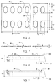
- FIG. 5 shows a perspective view of a possible embodiment of such Abschalungsplatte 5, wherein the weak points or predetermined breaking points are formed as a pan-shaped recesses 33 on one side or both sides in the surface or the opposite main sides 34 of the Abschalungsplatte 5.
- Such shuttering plates 5 can be attached to the reinforcements 31 by means of one or both sides of the shuttering plates 5 on the reinforcements 31 or snap-on clamping or holding elements 41, as shown in FIG. 5 is shown as an example. Of course, other fastening means may be provided.
- FIG. 6 shows one of the two main sides 34 of the Abschalungsplatte. 5
- FIG. 7 shows an end view of the Abschalungsplatte 5 and FIG. 8 a detail thereof in the region of the recesses 33.
- the recesses 33 are located on both main sides 34 directly opposite. You can, for example, at regular intervals a ( Fig. 6 ) may be arranged in two parallel rows along the longitudinal sides of the shuttering plate 5.
- FIG. 9 shows a detail of a corresponding plate 5 in the region of a recess 33.
- the positions of the weak points are recognizable even with such plates 5 from both main sides 34 forth, can be attached to the flat main page 34 at the appropriate locations, if necessary, marks, for example in shape from Small depressions or through holes with a small diameter (eg 1 to 3 mm) and a small mutual distance in the order of, for example, 1mm to about 10mm.
- marks for example in shape from Small depressions or through holes with a small diameter (eg 1 to 3 mm) and a small mutual distance in the order of, for example, 1mm to about 10mm.
- the weak points can also be identified, for example, by an imprint or by other colors.
- the inventive shuttering panels 5 can be made in large lengths 1 of several meters and usually shortened when required for example by sawing or be cut to length. Lengths in the range from about 2 m to about 4 m, for example 2.8 m, are advantageous.
- Weak points for the passage of reinforcing elements 31 are preferably arranged in rows, wherein adjacent recesses 33 are each offset by a distance a of preferably about 50mm to each other.
- the arrangement, shape, size and number of inventively formed vulnerabilities can be adjusted in any way to the particular application.
- the height h2 of the oval recesses 33 is in accordance with an embodiment FIG. 6 preferably about 45mm.
- the distance h1 of the recesses 33 from the associated edges of the shuttering panel 5 is preferably about 20mm.
- the arrangement of the recesses 33 corresponds to possible arrangements of reinforcements 31 which are intended to penetrate the intermediate shuttering.
- the offset or distance a of two adjacent depressions 33 is dimensioned such that an integer multiple thereof corresponds to the average distance between two adjacent reinforcing bars.
- the invention comprises, in addition to planar shuttering panels 5, also those with curves and corners. With such elements intermediate formwork can be made with any shape.
- the inventive shuttering panels 5 can, with appropriate training both as formwork elements for Intermediate formwork can also be used for edge shuttering.
- the surface of the shuttering plate 5 may be formed on one and / or on both main sides 34 smooth and / or rough. Surfaces to be joined to a concrete part are preferably rough.
- the surface roughness can be predetermined, for example, by the shape or by suitable process steps, such as the sprinkling of chippings or by mechanical processing of the respective surface. In the case of curing potting compounds this can be done before, during or after curing. Surfaces which are to be separated again from a concrete part, or which are visible later, are preferably flat and smooth. In those shuttering plates 5 which are produced by casting, foaming or pressing with a mold, the surface finish can be particularly easily determined by the nature of the surface of the mold.
- a shuttering plate 5, as in the FIGS. 5 to 9 can be, for example, mainly or completely made of compressed wood, concrete, plastic or cardboard.
- Sheathing panels 5 of fiber concrete are preferably cast in a horizontally lying mold (not shown) with frustoconical elevations, these elevations being coated only with one thin layer 36 each having a thickness d2 of, for example, 1 mm or less to about 5 mm of the cast material.
- These thin layers 36 Form after curing of the casting compound the weak points or predetermined breaking points. In this embodiment they are made of the same material as the remaining areas of the shuttering plate 5.
- the fibers can reinforce the weak points so that they can withstand pressures occurring during concreting and can be penetrated by hard objects such as reinforcing bars without breaking the edges of the holes is.
- the weak points are in this embodiment not inside the plate 5, but outside, arranged on one of the main sides 34 flush with the surface thereof. Alternatively or additionally, weak points may also be limited by perforations which are arranged along a closed line and form the edge of the weak points.
- the holes may be formed as round or slit-like elongated openings with a diameter or clear dimension of, for example, about 1 mm to 3 mm. Adjacent holes can each have a spacing of the same order (no representation).
- Such perforations can basically be formed both in lost and in reusable Abschalplatten 5 for edge or intermediate formworks of any thickness, regardless of whether these with or without holes 19 for retaining bracket 7 (FIG. Figures 1 and 2 ) and / or with not or are partially formed from the Abschalplatte 5 excellent reinforcement 17 or without reinforcement 17.
- perforations can also be formed in pressed, foamed or otherwise manufactured plates. For plates with holes 19 and recesses 33 and / or perforations may be provided which intersect or penetrate the holes 19. An assembly of such Abschalungsplatten 5 by means of brackets 7 or angles, which are each introduced with one of its legs in a respective bore 19, is thus easily possible.
- the thickness or thickness d1 of the Abschalplatten 5 may, for example, in the range of about 6mm to about 50mm.
- brittle material such as fiber concrete
- the formed as a weak point thin layer 36 may, as in FIG. 9 be arranged on one of the main sides 34 and flush with the surface thereof.
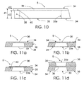
- the shuttering plate 5 can have not one but two comprising essential layers, namely a main plate 38 (FIG. FIG. 10 ) of thickness d3 and a thin plate 36 comprehensive, connected to the main plate 38 flat plate 40 of thickness d2.
- the thickness d1 of the shuttering plate 5 substantially corresponds to the sum of the thicknesses d2 of the main plate 38 and d3 of the further plate 40.
- the main plate 38 comprises recesses 33a in the region of the weak points. These are unilaterally covered by the further plate 40 and thus form the recesses 33 in the Abschalungsplatte 5.
- the thin layer 36 and the thin further plate 40 can be made of the same material as the main plate 38 and glued to this example, anchored or in be connected in any other way.
- the further plate 40 or the thin layer 36 may also be made of a different material or comprise materials other than the main plate 38.
- the term "further plate 40" expressly also includes thin layers that are flexible.
- it is possible to produce the further plates 40 or the thin layers 36 for example from woven fabrics, films, tiles, cardboard, wood-based materials and the like, and to anchor them to the main plate 38 before or during hardening.
- the thin layer 36 or plate 40 can for this purpose, for example, angled tongues or pins 43 (FIG. Fig. 11c ) or other areas immersed in the casting material.
- thin layers 36 or plates 40 for example, by gluing or be connected by other joining techniques with main plates 38.
- the stable or resistant areas comprise only one or at most two essential layers.
- the regions or weak points which can be punctured by reinforcements 31 comprise only one essential layer, this layer projecting beyond the weak points.
- the essential layers are at least approximately impermeable to a thick concrete mass. They are referred to as "essential layers” because they ensure the required properties of the shuttering panels 5 in the respective areas, namely the at least approximate impermeability to thick concrete in the area of the entire shuttering panel 5, the sufficiently high stability or impact resistance of the shuttering panels 5 in the stable or resistant zones of Abschalungsplatte 5 outside the weak points and easy fürstossiana the Abschalungsplatte 5 in the area of vulnerabilities.
- the weak points can be formed as thin spots or perforations in this one essential layer.
- cast Schalalplatten 5 eg fiber cement or concrete
- pot-like weak points can be made for example by truncated cone-like cones in the mold.
- thin areas can be formed, for example, in pressed plates of wood or other materials by mechanical reworking of these plates, for example by milling.
- the material of such monolayer Abschalungsplatten 5 is in the region of the weak points identical to the base material or the matrix of the remaining areas of Abschalungsplatte 5.
- the weak points are made of the same material or the same materials as the immediately adjacent to the weak points areas of Abschalungsplatte 5th
- the two plates 38, 40 can be made of the same or alternatively of different materials , Since the plate 40 laterally surmounts the weak points, the material composition of the shuttering plate 5, at least adjacent to the weak points and at least in the area of one of the surfaces or main sides 34 of the shuttering plates 5, is identical to that of the thin layer 36 in the area of the weak points
- FIGS. 11a to 11d show detailed cross sections in the region of a weak point for some possible embodiments of the shuttering plate 5.
- the shuttering plate 5 comprises only one layer, namely the main plate 38 made of fiber cement or other suitable material.
- the weak points are formed by pan-like recesses 33 as brittle thin layers 36 in the integrally cast main plate 38.
- Such depressions 33 can, as in FIG. 11a one-sided or according to FIG. 8 be inserted into the shuttering plate 5 from both main sides 34 ago.
- the thin layer 36 may therefore be arranged flush with respect to the two main sides 34, for example, or in any other position.
- a protective layer (not shown) which does not materially affect the puncture of the weak spots.
- a protective layer is not an essential layer in the sense of the present invention.
- Shuttering plate 5 shown comprises two essential layers, namely the main plate 38 with the recesses 33 and the thin further plate 40, which is connected to the main plate 38 and this completely covers. Those areas of the further plate 40, which cover the recesses 33a like a membrane, form the weak points of the shuttering plate 5.
- the recesses 33a can be formed with conical or vertical boundary walls.
- FIG. 11c shows a further variant of the Abschalungsplatte 5, wherein compared to FIG. 11b only the recesses 33a and the immediately following areas of the main plate 38 are each covered with a thin layer 36.
- each thin layer 36 extends beyond the edge of the respectively associated recess 33a or overlaps this edge and is held or fastened in or on the region of the shuttering plate 5 adjoining the recess 33a.
- the thin layers 36 thus only cover part of the respective main side 34.
- Each of the thin layers 36 may comprise, for example, one or more pins 43 projecting into the main plate 38 or other holding elements for anchoring in the main plate 38.
- two main plates 38 are connected to a shuttering plate 5, wherein one of the main plates 38 includes recesses 33a and the other main plate 38 includes recesses 33 defined by thin layers 36.
- the recesses 33a and the depressions 33 lie directly opposite one another and preferably have the same or similar shape and size in the region of the thin layers 36.
- a common feature of these embodiments is that at least on one of the main sides 34 of the Abschalungsplatte 5, the material or the material composition in the weak points is the same as in the immediately adjacent to the weak points areas of Abschalungsplatte. 5
- the shuttering plate 5 may additionally comprise a reinforcement 17.
- Such reinforcements 17 may be integrally formed or comprise a plurality of non-interconnected parts.
- the weak points are free of reinforcement.
- Subregions of the reinforcement 17 preferably project beyond one or both of the main sides 34. They may, for example (as in FIG FIG. 3 shown) angled portions 23 with holes 27 for attaching Include retaining clips 7.
- the reinforcing structures can be connected to the shuttering plate 5, for example by gluing or other joining techniques on the surface or one of the main sides 34.
- the reinforcing structures are preferably at least partially embedded in these shuttering plates 5.
- the reinforcement 17 can be inserted or immersed in the casting compound with any desired predeterminable immersion depth.
- the immersion depth preferably corresponds to approximately half the thickness d1 of the plate 5.
- one or both layers or layers with a reinforcement 17 can be reinforced in an analogous manner even in the case of two-layer shuttering plates 5.
- two or more vertically aligned shapes may be formed side by side, thereby enabling simultaneous filling of multiple shapes.
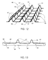
- FIG. 12 shows such a wire mesh 45 with welded longitudinal straight wires 47 and multiply bent and / or kinked or deformed transverse wires 49, which have a diameter in the order of about 0.5mm to about 6mm or preferably to about 5mm or corresponding cross-sectional areas in the order from about 0.2mm 2 to about 30mm 2 .
- the transverse wires 49 preferably have a relatively small diameter, for example 1.5 mm, and the longitudinal wires 47 have a somewhat larger diameter, for example 2.5 mm.
- Such grids can be made by simultaneously rolling several (eg five) to many (eg fifty) transverse wires 49 and periodically welding together with longitudinal wires 47 and then forming the transverse wires 49.
- longitudinal wires 47 could be handled simultaneously in an analogous manner and periodically connected to transverse wires 49.
- the welding of a longitudinal wire 47 with a plurality of transverse wires 49 can be carried out sequentially or preferably simultaneously.
- the initially planar wire mesh 45 or its transverse wires 49 are preferably reshaped such that wave-shaped regions 51 protrude from the lattice plane.
- the adjacent maxima 53 or convexly curved peaks Adjacent transverse wires 49 are connected to each other by an outer or welded-up top longitudinal wire 47.
- each transverse wire 49 is concavely curved and each transitions into a linear section 55 lying in the lattice plane.
- the transverse wires 49 are connected analogously to the wave crests by longitudinal wires 47 on the upper side of the grating.
- Each two adjacent longitudinal wires 47 and each two adjacent transverse wires 49 thus frame in the lattice plane in each case rectangular or square grid openings 57th
- FIG. 13 shows a shuttering panel 5 with a wireframe reinforcement seen from one of the narrow end faces.
- the transverse wires 49 project beyond the upper main side 34 of the shuttering plate 5 in the region of two peaks.
- the there connected to the transverse wires 49 longitudinal wires 47 are completely outside of the integrally cast main plate 38.
- the recesses 33 which form the weak points of Abschalungsplatte 5, are arranged in the region of the grid openings 57, wherein the legs of two longitudinal wires 47 and two transverse wires 49th framed, but not directly adjacent to these.
- the plate thickness is so low that these areas, for example by Whipping with a hammer can be broken completely or partially.
- Abschalungsplatte 5 as an intermediate formwork reinforcements 31 can easily penetrate the Abschalungsplatte 5 in the area of weak points when the Abschalungsplatte 5 is pressed or beaten against the ends of the protruding reinforcing rods (or vice versa).
- the disc-like vulnerability is completely broken out of the shuttering plate 5 or penetrate the reinforcing rods - similar to a nail that is hammered - the weak points, without breaking the entire disc of the vulnerability.
- Shuttering plates 5 may also be curved and / or comprise a plurality of sections, wherein each two adjoining sections each include a fixed or - in the case of hinge-like sections - a variable angle.
Landscapes
- Engineering & Computer Science (AREA)
- Architecture (AREA)
- Physics & Mathematics (AREA)
- Electromagnetism (AREA)
- Civil Engineering (AREA)
- Structural Engineering (AREA)
- Forms Removed On Construction Sites Or Auxiliary Members Thereof (AREA)
- Moulds, Cores, Or Mandrels (AREA)
Applications Claiming Priority (1)
| Application Number | Priority Date | Filing Date | Title |
|---|---|---|---|
| CH732007 | 2007-01-17 |
Publications (3)
| Publication Number | Publication Date |
|---|---|
| EP1947256A2 true EP1947256A2 (fr) | 2008-07-23 |
| EP1947256A3 EP1947256A3 (fr) | 2013-05-01 |
| EP1947256B1 EP1947256B1 (fr) | 2016-03-23 |
Family
ID=39357742
Family Applications (1)
| Application Number | Title | Priority Date | Filing Date |
|---|---|---|---|
| EP08405013.7A Active EP1947256B1 (fr) | 2007-01-17 | 2008-01-17 | Dispositif de coffrage |
Country Status (1)
| Country | Link |
|---|---|
| EP (1) | EP1947256B1 (fr) |
Cited By (2)
| Publication number | Priority date | Publication date | Assignee | Title |
|---|---|---|---|---|
| EP2320001A2 (fr) | 2009-10-27 | 2011-05-11 | Pino Albanese | Dispositif d'établissement d'un coffrage partiel et/ou d'un coffrage à joint de dilatation sur une construction en béton |
| WO2015059322A1 (fr) * | 2013-10-25 | 2015-04-30 | Universidad De Sevilla | Système structurel contre le pont thermique dans les faces de planchers pour façades en céramique |
Citations (2)
| Publication number | Priority date | Publication date | Assignee | Title |
|---|---|---|---|---|
| EP0927796A1 (fr) | 1997-12-30 | 1999-07-07 | System Albanese | Panneau et système de coffrage |
| EP1327732A1 (fr) | 2001-12-24 | 2003-07-16 | System Albanese | Coffrage de rive pour dalles en béton |
Family Cites Families (4)
| Publication number | Priority date | Publication date | Assignee | Title |
|---|---|---|---|---|
| SE431667B (sv) * | 1982-06-15 | 1984-02-20 | Tremix Ab | System for anvendning vid gjutning av betonggolv samt sett och form for tillverkning av i systemet ingaende balkar |
| GB8709877D0 (en) * | 1987-04-27 | 1987-06-03 | Clifton R A | Concrete screed rails |
| EP0519146B1 (fr) * | 1991-06-17 | 1995-01-18 | Brefeba N.V. | Coffrage d'about |
| ATE531864T1 (de) * | 2002-11-21 | 2011-11-15 | Ankaba Ag | Abschalungsplatte sowie verfahren zu ihrer herstellung und befestigung |
-
2008
- 2008-01-17 EP EP08405013.7A patent/EP1947256B1/fr active Active
Patent Citations (2)
| Publication number | Priority date | Publication date | Assignee | Title |
|---|---|---|---|---|
| EP0927796A1 (fr) | 1997-12-30 | 1999-07-07 | System Albanese | Panneau et système de coffrage |
| EP1327732A1 (fr) | 2001-12-24 | 2003-07-16 | System Albanese | Coffrage de rive pour dalles en béton |
Cited By (3)
| Publication number | Priority date | Publication date | Assignee | Title |
|---|---|---|---|---|
| EP2320001A2 (fr) | 2009-10-27 | 2011-05-11 | Pino Albanese | Dispositif d'établissement d'un coffrage partiel et/ou d'un coffrage à joint de dilatation sur une construction en béton |
| WO2015059322A1 (fr) * | 2013-10-25 | 2015-04-30 | Universidad De Sevilla | Système structurel contre le pont thermique dans les faces de planchers pour façades en céramique |
| ES2537251A1 (es) * | 2013-10-25 | 2015-06-03 | Universidad De Sevilla | Sistema estructural contra el puente térmico en frente de forjados para fachadas cerámicas |
Also Published As
| Publication number | Publication date |
|---|---|
| EP1947256A3 (fr) | 2013-05-01 |
| EP1947256B1 (fr) | 2016-03-23 |
Similar Documents
| Publication | Publication Date | Title |
|---|---|---|
| DE69128482T2 (de) | Plattenmodul aus geschäumtem kunststoff mit versetzten t-förmigen längskanälen für hölzerne stützen | |
| DE60314459T2 (de) | Bauelement für die mantelbetonbauweise | |
| AT410567B (de) | Deckenrandschalenelement sowie verwendung desselben | |
| DE1658991A1 (de) | Baukonstruktion und Verfahren und Mittel zu ihrer Herstellung | |
| EP2963205B1 (fr) | Dispositif de coffrage | |
| DE202004004965U1 (de) | Schalungselement | |
| DE19516098B4 (de) | Deckenrandschalungselement sowie Verfahren und Vorrichtung zu seiner Herstellung | |
| DE19758238A1 (de) | Schalungssystem | |
| EP1947256B1 (fr) | Dispositif de coffrage | |
| EP1947255B1 (fr) | Armature pour plaques de décoffrage | |
| EP1842984B1 (fr) | Plaque de coffrage profilée de bordure de dalle en béton | |
| DE19643800C2 (de) | Wandschalung | |
| DE1946462A1 (de) | Isolierte Mauer fuer Gebaeudewaende | |
| EP1972734A1 (fr) | Corps de fixation pour un panneau isolant | |
| WO1994017258A1 (fr) | Element de construction | |
| DE3214502A1 (de) | Plattenfoermiges bauelement fuer die mantelbetonbauweise | |
| DE19636828C2 (de) | Verfahren und Bauelement zur Herstellung von Bauwerksteilen | |
| DE102012021213A1 (de) | Randschalungselement und Randschalungs-Verfahren | |
| DE19625514C2 (de) | Schalenbauteil für Wände oder Decken und Verfahren zur Herstellung des Schalenbauteils | |
| EP3524745B1 (fr) | Composant destiné à l'absorption de bruit | |
| DE29602697U1 (de) | Schalung | |
| DE8411952U1 (de) | Verlorene Schalung für tragende Gebäudeteile aus Beton, insbesondere für Gebäudedecken, Ringanker und Stürze | |
| AT412295B (de) | Hohlwand - verbindungsträger für vollflächiges aufbringen von wärmedämmplatten auf der innenseiteder verlorenen schalung | |
| DE29903635U1 (de) | Ein Dämm- u. verlorenes Schalelement | |
| DE2264362A1 (de) | Verlorene schalungsplatte |
Legal Events
| Date | Code | Title | Description |
|---|---|---|---|
| PUAI | Public reference made under article 153(3) epc to a published international application that has entered the european phase |
Free format text: ORIGINAL CODE: 0009012 |
|
| AK | Designated contracting states |
Kind code of ref document: A2 Designated state(s): AT BE BG CH CY CZ DE DK EE ES FI FR GB GR HR HU IE IS IT LI LT LU LV MC MT NL NO PL PT RO SE SI SK TR |
|
| AX | Request for extension of the european patent |
Extension state: AL BA MK RS |
|
| PUAL | Search report despatched |
Free format text: ORIGINAL CODE: 0009013 |
|
| AK | Designated contracting states |
Kind code of ref document: A3 Designated state(s): AT BE BG CH CY CZ DE DK EE ES FI FR GB GR HR HU IE IS IT LI LT LU LV MC MT NL NO PL PT RO SE SI SK TR |
|
| AX | Request for extension of the european patent |
Extension state: AL BA MK RS |
|
| RIC1 | Information provided on ipc code assigned before grant |
Ipc: E04B 5/32 20060101AFI20130328BHEP |
|
| 17P | Request for examination filed |
Effective date: 20130826 |
|
| RBV | Designated contracting states (corrected) |
Designated state(s): AT BE BG CH CY CZ DE DK EE ES FI FR GB GR HR HU IE IS IT LI LT LU LV MC MT NL NO PL PT RO SE SI SK TR |
|
| AKX | Designation fees paid |
Designated state(s): AT BE BG CH CY CZ DE DK EE ES FI FR GB GR HR HU IE IS IT LI LT LU LV MC MT NL NO PL PT RO SE SI SK TR |
|
| 17Q | First examination report despatched |
Effective date: 20141104 |
|
| GRAP | Despatch of communication of intention to grant a patent |
Free format text: ORIGINAL CODE: EPIDOSNIGR1 |
|
| INTG | Intention to grant announced |
Effective date: 20150910 |
|
| GRAS | Grant fee paid |
Free format text: ORIGINAL CODE: EPIDOSNIGR3 |
|
| GRAA | (expected) grant |
Free format text: ORIGINAL CODE: 0009210 |
|
| AK | Designated contracting states |
Kind code of ref document: B1 Designated state(s): AT BE BG CH CY CZ DE DK EE ES FI FR GB GR HR HU IE IS IT LI LT LU LV MC MT NL NO PL PT RO SE SI SK TR |
|
| REG | Reference to a national code |
Ref country code: GB Ref legal event code: FG4D Free format text: NOT ENGLISH |
|
| REG | Reference to a national code |
Ref country code: CH Ref legal event code: EP |
|
| REG | Reference to a national code |
Ref country code: AT Ref legal event code: REF Ref document number: 783310 Country of ref document: AT Kind code of ref document: T Effective date: 20160415 |
|
| REG | Reference to a national code |
Ref country code: IE Ref legal event code: FG4D Free format text: LANGUAGE OF EP DOCUMENT: GERMAN |
|
| REG | Reference to a national code |
Ref country code: CH Ref legal event code: NV Representative=s name: GACHNANG AG PATENTANWAELTE, CH |
|
| REG | Reference to a national code |
Ref country code: DE Ref legal event code: R096 Ref document number: 502008013967 Country of ref document: DE |
|
| REG | Reference to a national code |
Ref country code: LT Ref legal event code: MG4D |
|
| REG | Reference to a national code |
Ref country code: NL Ref legal event code: MP Effective date: 20160323 |
|
| PG25 | Lapsed in a contracting state [announced via postgrant information from national office to epo] |
Ref country code: NO Free format text: LAPSE BECAUSE OF FAILURE TO SUBMIT A TRANSLATION OF THE DESCRIPTION OR TO PAY THE FEE WITHIN THE PRESCRIBED TIME-LIMIT Effective date: 20160623 Ref country code: FI Free format text: LAPSE BECAUSE OF FAILURE TO SUBMIT A TRANSLATION OF THE DESCRIPTION OR TO PAY THE FEE WITHIN THE PRESCRIBED TIME-LIMIT Effective date: 20160323 Ref country code: GR Free format text: LAPSE BECAUSE OF FAILURE TO SUBMIT A TRANSLATION OF THE DESCRIPTION OR TO PAY THE FEE WITHIN THE PRESCRIBED TIME-LIMIT Effective date: 20160624 |
|
| PG25 | Lapsed in a contracting state [announced via postgrant information from national office to epo] |
Ref country code: LV Free format text: LAPSE BECAUSE OF FAILURE TO SUBMIT A TRANSLATION OF THE DESCRIPTION OR TO PAY THE FEE WITHIN THE PRESCRIBED TIME-LIMIT Effective date: 20160323 Ref country code: NL Free format text: LAPSE BECAUSE OF FAILURE TO SUBMIT A TRANSLATION OF THE DESCRIPTION OR TO PAY THE FEE WITHIN THE PRESCRIBED TIME-LIMIT Effective date: 20160323 Ref country code: SE Free format text: LAPSE BECAUSE OF FAILURE TO SUBMIT A TRANSLATION OF THE DESCRIPTION OR TO PAY THE FEE WITHIN THE PRESCRIBED TIME-LIMIT Effective date: 20160323 Ref country code: LT Free format text: LAPSE BECAUSE OF FAILURE TO SUBMIT A TRANSLATION OF THE DESCRIPTION OR TO PAY THE FEE WITHIN THE PRESCRIBED TIME-LIMIT Effective date: 20160323 |
|
| PG25 | Lapsed in a contracting state [announced via postgrant information from national office to epo] |
Ref country code: IS Free format text: LAPSE BECAUSE OF FAILURE TO SUBMIT A TRANSLATION OF THE DESCRIPTION OR TO PAY THE FEE WITHIN THE PRESCRIBED TIME-LIMIT Effective date: 20160723 Ref country code: PL Free format text: LAPSE BECAUSE OF FAILURE TO SUBMIT A TRANSLATION OF THE DESCRIPTION OR TO PAY THE FEE WITHIN THE PRESCRIBED TIME-LIMIT Effective date: 20160323 Ref country code: EE Free format text: LAPSE BECAUSE OF FAILURE TO SUBMIT A TRANSLATION OF THE DESCRIPTION OR TO PAY THE FEE WITHIN THE PRESCRIBED TIME-LIMIT Effective date: 20160323 |
|
| PG25 | Lapsed in a contracting state [announced via postgrant information from national office to epo] |
Ref country code: CZ Free format text: LAPSE BECAUSE OF FAILURE TO SUBMIT A TRANSLATION OF THE DESCRIPTION OR TO PAY THE FEE WITHIN THE PRESCRIBED TIME-LIMIT Effective date: 20160323 Ref country code: PT Free format text: LAPSE BECAUSE OF FAILURE TO SUBMIT A TRANSLATION OF THE DESCRIPTION OR TO PAY THE FEE WITHIN THE PRESCRIBED TIME-LIMIT Effective date: 20160725 Ref country code: SK Free format text: LAPSE BECAUSE OF FAILURE TO SUBMIT A TRANSLATION OF THE DESCRIPTION OR TO PAY THE FEE WITHIN THE PRESCRIBED TIME-LIMIT Effective date: 20160323 Ref country code: RO Free format text: LAPSE BECAUSE OF FAILURE TO SUBMIT A TRANSLATION OF THE DESCRIPTION OR TO PAY THE FEE WITHIN THE PRESCRIBED TIME-LIMIT Effective date: 20160323 Ref country code: ES Free format text: LAPSE BECAUSE OF FAILURE TO SUBMIT A TRANSLATION OF THE DESCRIPTION OR TO PAY THE FEE WITHIN THE PRESCRIBED TIME-LIMIT Effective date: 20160323 |
|
| PG25 | Lapsed in a contracting state [announced via postgrant information from national office to epo] |
Ref country code: IT Free format text: LAPSE BECAUSE OF FAILURE TO SUBMIT A TRANSLATION OF THE DESCRIPTION OR TO PAY THE FEE WITHIN THE PRESCRIBED TIME-LIMIT Effective date: 20160323 |
|
| REG | Reference to a national code |
Ref country code: DE Ref legal event code: R097 Ref document number: 502008013967 Country of ref document: DE |
|
| PLBE | No opposition filed within time limit |
Free format text: ORIGINAL CODE: 0009261 |
|
| STAA | Information on the status of an ep patent application or granted ep patent |
Free format text: STATUS: NO OPPOSITION FILED WITHIN TIME LIMIT |
|
| PG25 | Lapsed in a contracting state [announced via postgrant information from national office to epo] |
Ref country code: DK Free format text: LAPSE BECAUSE OF FAILURE TO SUBMIT A TRANSLATION OF THE DESCRIPTION OR TO PAY THE FEE WITHIN THE PRESCRIBED TIME-LIMIT Effective date: 20160323 |
|
| PG25 | Lapsed in a contracting state [announced via postgrant information from national office to epo] |
Ref country code: BG Free format text: LAPSE BECAUSE OF FAILURE TO SUBMIT A TRANSLATION OF THE DESCRIPTION OR TO PAY THE FEE WITHIN THE PRESCRIBED TIME-LIMIT Effective date: 20160623 |
|
| 26N | No opposition filed |
Effective date: 20170102 |
|
| PG25 | Lapsed in a contracting state [announced via postgrant information from national office to epo] |
Ref country code: SI Free format text: LAPSE BECAUSE OF FAILURE TO SUBMIT A TRANSLATION OF THE DESCRIPTION OR TO PAY THE FEE WITHIN THE PRESCRIBED TIME-LIMIT Effective date: 20160323 Ref country code: BE Free format text: LAPSE BECAUSE OF NON-PAYMENT OF DUE FEES Effective date: 20170131 |
|
| PG25 | Lapsed in a contracting state [announced via postgrant information from national office to epo] |
Ref country code: MC Free format text: LAPSE BECAUSE OF FAILURE TO SUBMIT A TRANSLATION OF THE DESCRIPTION OR TO PAY THE FEE WITHIN THE PRESCRIBED TIME-LIMIT Effective date: 20160323 |
|
| REG | Reference to a national code |
Ref country code: FR Ref legal event code: ST Effective date: 20170929 |
|
| PG25 | Lapsed in a contracting state [announced via postgrant information from national office to epo] |
Ref country code: FR Free format text: LAPSE BECAUSE OF NON-PAYMENT OF DUE FEES Effective date: 20170131 |
|
| REG | Reference to a national code |
Ref country code: IE Ref legal event code: MM4A |
|
| PG25 | Lapsed in a contracting state [announced via postgrant information from national office to epo] |
Ref country code: LU Free format text: LAPSE BECAUSE OF NON-PAYMENT OF DUE FEES Effective date: 20170117 |
|
| REG | Reference to a national code |
Ref country code: BE Ref legal event code: MM Effective date: 20170131 |
|
| PG25 | Lapsed in a contracting state [announced via postgrant information from national office to epo] |
Ref country code: IE Free format text: LAPSE BECAUSE OF NON-PAYMENT OF DUE FEES Effective date: 20170117 |
|
| PG25 | Lapsed in a contracting state [announced via postgrant information from national office to epo] |
Ref country code: MT Free format text: LAPSE BECAUSE OF FAILURE TO SUBMIT A TRANSLATION OF THE DESCRIPTION OR TO PAY THE FEE WITHIN THE PRESCRIBED TIME-LIMIT Effective date: 20160323 |
|
| PG25 | Lapsed in a contracting state [announced via postgrant information from national office to epo] |
Ref country code: HU Free format text: LAPSE BECAUSE OF FAILURE TO SUBMIT A TRANSLATION OF THE DESCRIPTION OR TO PAY THE FEE WITHIN THE PRESCRIBED TIME-LIMIT; INVALID AB INITIO Effective date: 20080117 |
|
| PG25 | Lapsed in a contracting state [announced via postgrant information from national office to epo] |
Ref country code: CY Free format text: LAPSE BECAUSE OF NON-PAYMENT OF DUE FEES Effective date: 20160323 |
|
| PG25 | Lapsed in a contracting state [announced via postgrant information from national office to epo] |
Ref country code: TR Free format text: LAPSE BECAUSE OF FAILURE TO SUBMIT A TRANSLATION OF THE DESCRIPTION OR TO PAY THE FEE WITHIN THE PRESCRIBED TIME-LIMIT Effective date: 20160323 |
|
| PG25 | Lapsed in a contracting state [announced via postgrant information from national office to epo] |
Ref country code: HR Free format text: LAPSE BECAUSE OF FAILURE TO SUBMIT A TRANSLATION OF THE DESCRIPTION OR TO PAY THE FEE WITHIN THE PRESCRIBED TIME-LIMIT Effective date: 20160323 |
|
| REG | Reference to a national code |
Ref country code: CH Ref legal event code: PK Free format text: BERICHTIGUNGEN |
|
| REG | Reference to a national code |
Ref country code: CH Ref legal event code: U11 Free format text: ST27 STATUS EVENT CODE: U-0-0-U10-U11 (AS PROVIDED BY THE NATIONAL OFFICE) Effective date: 20260201 |
|
| PGFP | Annual fee paid to national office [announced via postgrant information from national office to epo] |
Ref country code: GB Payment date: 20260122 Year of fee payment: 19 |
|
| PGFP | Annual fee paid to national office [announced via postgrant information from national office to epo] |
Ref country code: DE Payment date: 20260120 Year of fee payment: 19 |
|
| PGFP | Annual fee paid to national office [announced via postgrant information from national office to epo] |
Ref country code: AT Payment date: 20260119 Year of fee payment: 19 |
|
| PGFP | Annual fee paid to national office [announced via postgrant information from national office to epo] |
Ref country code: CH Payment date: 20260201 Year of fee payment: 19 |