EP1947263A1 - Automatische klettervorrichtung für hebestrukturen und dacheindeckung - Google Patents
Automatische klettervorrichtung für hebestrukturen und dacheindeckung Download PDFInfo
- Publication number
- EP1947263A1 EP1947263A1 EP06830887A EP06830887A EP1947263A1 EP 1947263 A1 EP1947263 A1 EP 1947263A1 EP 06830887 A EP06830887 A EP 06830887A EP 06830887 A EP06830887 A EP 06830887A EP 1947263 A1 EP1947263 A1 EP 1947263A1
- Authority
- EP
- European Patent Office
- Prior art keywords
- climbing
- heads
- support track
- roofing
- lifting structures
- Prior art date
- Legal status (The legal status is an assumption and is not a legal conclusion. Google has not performed a legal analysis and makes no representation as to the accuracy of the status listed.)
- Withdrawn
Links
- 230000009194 climbing Effects 0.000 title claims abstract description 83
- 230000000903 blocking effect Effects 0.000 claims abstract description 45
- 230000009471 action Effects 0.000 claims abstract description 15
- 230000007246 mechanism Effects 0.000 claims abstract description 5
- 238000010276 construction Methods 0.000 claims description 16
- 230000008878 coupling Effects 0.000 description 4
- 238000010168 coupling process Methods 0.000 description 4
- 238000005859 coupling reaction Methods 0.000 description 4
- 238000000034 method Methods 0.000 description 3
- 230000006872 improvement Effects 0.000 description 2
- 238000009434 installation Methods 0.000 description 2
- 239000000463 material Substances 0.000 description 2
- 230000008569 process Effects 0.000 description 2
- 230000008901 benefit Effects 0.000 description 1
- 230000015572 biosynthetic process Effects 0.000 description 1
- 230000000295 complement effect Effects 0.000 description 1
- 239000002184 metal Substances 0.000 description 1
Images



Classifications
-
- E—FIXED CONSTRUCTIONS
- E04—BUILDING
- E04B—GENERAL BUILDING CONSTRUCTIONS; WALLS, e.g. PARTITIONS; ROOFS; FLOORS; CEILINGS; INSULATION OR OTHER PROTECTION OF BUILDINGS
- E04B1/00—Constructions in general; Structures which are not restricted either to walls, e.g. partitions, or floors or ceilings or roofs
- E04B1/35—Extraordinary methods of construction, e.g. lift-slab, jack-block
- E04B1/3511—Lift-slab; characterised by a purely vertical lifting of floors or roofs or parts thereof
-
- B—PERFORMING OPERATIONS; TRANSPORTING
- B66—HOISTING; LIFTING; HAULING
- B66F—HOISTING, LIFTING, HAULING OR PUSHING, NOT OTHERWISE PROVIDED FOR, e.g. DEVICES WHICH APPLY A LIFTING OR PUSHING FORCE DIRECTLY TO THE SURFACE OF A LOAD
- B66F1/00—Devices, e.g. jacks, for lifting loads in predetermined steps
- B66F1/02—Devices, e.g. jacks, for lifting loads in predetermined steps with locking elements, e.g. washers, co-operating with posts
- B66F1/025—Devices, e.g. jacks, for lifting loads in predetermined steps with locking elements, e.g. washers, co-operating with posts the devices being operated by fluid pressure
-
- E—FIXED CONSTRUCTIONS
- E04—BUILDING
- E04B—GENERAL BUILDING CONSTRUCTIONS; WALLS, e.g. PARTITIONS; ROOFS; FLOORS; CEILINGS; INSULATION OR OTHER PROTECTION OF BUILDINGS
- E04B1/00—Constructions in general; Structures which are not restricted either to walls, e.g. partitions, or floors or ceilings or roofs
- E04B1/35—Extraordinary methods of construction, e.g. lift-slab, jack-block
- E04B1/3522—Extraordinary methods of construction, e.g. lift-slab, jack-block characterised by raising a structure and then adding structural elements under it
- E04B1/3527—Extraordinary methods of construction, e.g. lift-slab, jack-block characterised by raising a structure and then adding structural elements under it the structure being a roof
-
- E—FIXED CONSTRUCTIONS
- E04—BUILDING
- E04B—GENERAL BUILDING CONSTRUCTIONS; WALLS, e.g. PARTITIONS; ROOFS; FLOORS; CEILINGS; INSULATION OR OTHER PROTECTION OF BUILDINGS
- E04B7/00—Roofs; Roof construction with regard to insulation
- E04B7/16—Roof structures with movable roof parts
-
- E—FIXED CONSTRUCTIONS
- E04—BUILDING
- E04G—SCAFFOLDING; FORMS; SHUTTERING; BUILDING IMPLEMENTS OR AIDS, OR THEIR USE; HANDLING BUILDING MATERIALS ON THE SITE; REPAIRING, BREAKING-UP OR OTHER WORK ON EXISTING BUILDINGS
- E04G21/00—Preparing, conveying, or working-up building materials or building elements in situ; Other devices or measures for constructional work
- E04G21/14—Conveying or assembling building elements
- E04G21/16—Tools or apparatus
-
- E—FIXED CONSTRUCTIONS
- E04—BUILDING
- E04G—SCAFFOLDING; FORMS; SHUTTERING; BUILDING IMPLEMENTS OR AIDS, OR THEIR USE; HANDLING BUILDING MATERIALS ON THE SITE; REPAIRING, BREAKING-UP OR OTHER WORK ON EXISTING BUILDINGS
- E04G21/00—Preparing, conveying, or working-up building materials or building elements in situ; Other devices or measures for constructional work
- E04G21/14—Conveying or assembling building elements
- E04G21/16—Tools or apparatus
- E04G21/163—Jacks specially adapted for working-up building elements
-
- E—FIXED CONSTRUCTIONS
- E04—BUILDING
- E04B—GENERAL BUILDING CONSTRUCTIONS; WALLS, e.g. PARTITIONS; ROOFS; FLOORS; CEILINGS; INSULATION OR OTHER PROTECTION OF BUILDINGS
- E04B1/00—Constructions in general; Structures which are not restricted either to walls, e.g. partitions, or floors or ceilings or roofs
- E04B1/35—Extraordinary methods of construction, e.g. lift-slab, jack-block
- E04B2001/3588—Extraordinary methods of construction, e.g. lift-slab, jack-block using special lifting or handling devices, e.g. gantries, overhead conveying rails
Definitions
- the present invention relates to an automatic climbing device which, by means of a relative movement between a support track and the climbing heads, is intended to safely and simply lift structures and roofing previously built at a lower level using the actual construction or building as a support track, and which involves an alternative and/or improvement in this field in relation to the nature of the blocking device that it uses.
- the present invention is applicable within any industrial field, especially in the construction field in general, and particularly in civil constructions, constructions of hypermarkets, of industrial premises, pavilions or sports centers, singular buildings or constructions, etc., and in all those which require lifting large structures and roofing.
- Utility Model 1059902 relating to a "System for lifting roofing by means of multitowers, with the rise of the lifting carriage by means of a hydraulic climbing device" describes one of such systems consisting of lifting towers which are implemented at certain points of the surface to be covered incorporating a lifting carriage and outer guiding columns intended to absorb horizontal stress.
- Said system therefore has the drawback of having to assemble lifting towers as well as perimetrically placing guiding towers prior to the actual lifting of the structure, which means a high cost both in materials and in time used for that purpose.
- patent 2092397 relating to an "automatic climbing device for a climbing scaffold" describes a system in which the climbing heads have a rotating control element and a rotating blocking element, which in the path of the control element in the support track provides a control cam and that the control element and the blocking element are coupled to one another such that in direction of the movement the control cam rotates the blocking element by means of the control element such that the blocking element abuts against the blocking cam.
- This system allows the climbing heads to act in two opposite directions of movement, which can become a drawback because it may be unsafe due to any drawback in the movement or blocking of any of the parts or to an unsuitable handling.
- the first case describes a device formed by a hydraulic cylinder and two climbing heads moving forwards over the support track, which can be the own support track of the construction, being able to adapt to different support sizes having a blocking element formed by wedges
- the second case describes a similar device having a blocking element formed by balls or roller which are blocked on the support track, pressed under the action of a spring.
- An automatic climbing device for lifting structures and roofing has therefore been designed with the present invention, the main innovation of which consists of allowing the use of the actual posts, metal profiles or supports of the construction or building in question without any special preparation whichever the cross-section they may have.
- the device of the invention is basically formed by a support track, belonging to the actual construction as has been mentioned, to which respective climbing heads, an upper climbing head and another lower climbing head, are coupled, which climbing heads are connected by a hydraulic cylinder.
- connection between said climbing heads and the mentioned support track is carried out by means of friction force obtained by means of a blocking element which is blocked between the climbing head and the support track.
- This blocking element is one of the innovative and distinctive features of the invention, it can be roller-shaped or wedge-shaped, being pressed towards the blocking under the action of a counterweight and a spring to which it is joined.
- the climbing heads are unblocked under the action of the hydraulic cylinder connecting them in the direction of forward movement of the system, being blocked in the opposite direction or under the action of the load to be lifted.
- a climbing head remains fixed, connected to the support track by means of the blocking element which is pressed under the action of the counterweight or of the spring, whereas the other climbing head is automatically unblocked under the action of the hydraulic cylinder which allows the relative movement of said climbing head in relation to the support track;
- the hydraulic cylinder stops and this climbing head is blocked, the two heads being blocked at the same time by the pressing towards the blocking of the roller or wedge caused by respective counterweights or springs; the return of the cylinder then commences, the other climbing head is therefore automatically unblocked, the blocking element of the latter being released for that purpose and the relative movement of this climbing head in relation to the support track occurs; finally, after the run of the climbing head has been carried out, the hydraulic cylinder stops and both heads are blocked, the entire process being repeated again.
- the device has the particularity of operating in a single direction of movement, which assures to the actual system the safety against falls or unsuitable handling.
- the automatic climbing device further allows adapting it to the dimensions of posts or supports of the construction, especially those having a T- or I-shaped cross-section, along the way, at the same time as the installation of the system, thus being able to be adapted to any size that said posts may have, or size variation therein that may occur throughout their length, also avoiding possible bushings, screws or objects that it may have on the other side and that may hinder its passage while climbing, its coupling to posts of said type placed against a wall also being advantageously possible because it is only fixed at one of the sides of the post or support of the construction.
- the climbing heads have an embodiment variant the coupling of which to the support track occurs only at one of their sides, being configured such that, as mobile clamps or vises, they press the side branches of the T or of the I, slightly varying the arrangement of the remaining elements collaborating in the lifting and blocking movement.
- the blocking element thus takes the form of a double roller which is blocked on the support track and which is also pressed by a counterweight fixed to the head by a central shaft, respective coil springs being located at both ends of the actual shaft which are fixed such as to produce the necessary blocking and return mechanisms for the operation of the device.
- connection between said climbing heads and the mentioned support track is likewise carried out by friction force obtained by the blocking element which is blocked between the climbing head and the support track.
- the climbing heads are likewise unblocked under the action of the hydraulic cylinder connecting them in the direction of forward movement of the system, being blocked in the opposite direction or under the action of the load to be lifted.
- the way of fixing the climbing heads to the support track is carried out by means of clamps, which allows coupling them, without needing any special preparation, to any type of T- or I-shaped profile or support belonging to the actual building.
- the new automatic climbing device for lifting structures and roofing therefore represents an innovative structure with structural and constitutive features that were unknown up until now for such purpose, which reasons, in addition to its practical usefulness, provide it with the sufficient grounds for obtaining the exclusiveness privilege sought.
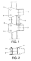
- the device of the invention is thus formed by respective climbing heads, an upper climbing head (1) and another lower climbing head (2), which are coupled by means of bolts (3) to the support track (4), which already forms part of the actual construction and which in the example shown is a beam having an 1-shaped cross-section, being able to be adapted to any other type of profile.
- Said climbing heads (1) and (2) are arranged at a certain distance from one another, connected by means of a hydraulic cylinder (5), the upper climbing head (1) supporting the weight of the load (6) or structure to be lifted, and have one blocking element (9) per climbing head.
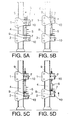
- This innovative blocking element (9) which can take the form of a roller, such as in the example shown, or of a wedge, and which is blocked on the support track (4) pressed under the action of a counterweight (7) fixed to the climbing head (1) and (2) by a central shaft (8), and fixed to the climbing head (1) and (2) by means of a coil spring (10) at the opposite end such as to produce the necessary blocking mechanism for the operation of the device ( Figures 3 and 4 ).
- the hydraulic cylinder (5) stops, actuating the blocking element (9) of this upper climbing head (1), the two climbing heads (1) and (2) being blocked at the same time, respectively pressed towards the blocking by the corresponding counterweights (7) and springs (10).
- the load (6) or structure is thus slowly lifted after the device has carried out, by means of the movement of the climbing heads (1) and (2), each of the described steps until reaching its final position.
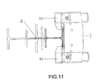
- the device of the invention is formed by respective climbing heads, an upper climbing head (1) and a lower climbing head (2), arranged at a certain distance from one another, connected by means of a hydraulic cylinder (5), the upper climbing head (1) supporting the weight of the load (6) or structure to be lifted, and which have a blocking element (9) per climbing head.
- said climbing heads (1) and (2) are configured such that they cover the side branches of the T or of the I in the example shown, such that they are coupled by means of respective mobile clamps (11) to the side branches of the support track (4) having an I-shaped cross-section, being fixed at only one of their sides, the opposite side being free, which allows adapting them to any dimension of said track (4).
- the blocking element (9) in turn takes the form of a double roller which is blocked on the support track (4) and which is also pressed by a counterweight (7) fixed to the head by a central shaft (8), respective coil springs (10) being located at both ends of the actual shaft (8) which are fixed such as to produce the necessary blocking and return mechanisms for the operation of the device.
- connection between said climbing heads (1) and (2) and the mentioned support track (4) is likewise carried out by means of the friction force obtained by the blocking element (9) which is blocked between them and the support track (4).
Landscapes
- Engineering & Computer Science (AREA)
- Architecture (AREA)
- Structural Engineering (AREA)
- Civil Engineering (AREA)
- Physics & Mathematics (AREA)
- Electromagnetism (AREA)
- Mechanical Engineering (AREA)
- Fluid Mechanics (AREA)
- Life Sciences & Earth Sciences (AREA)
- Geology (AREA)
- Conveying And Assembling Of Building Elements In Situ (AREA)
Applications Claiming Priority (3)
| Application Number | Priority Date | Filing Date | Title |
|---|---|---|---|
| ES200502577A ES2279703B1 (es) | 2005-10-21 | 2005-10-21 | Dispositivo autotrepador para elevacion de estructuras y cubiertas de edificios. |
| ES200602614A ES2298061B1 (es) | 2005-10-21 | 2006-10-16 | Perfecionamientos en el objeto de la patente n 200502577 por dispositivo autotrepador para elevacion de estructuras y cubiertas de edificios. |
| PCT/ES2006/000582 WO2007048863A1 (es) | 2005-10-21 | 2006-10-20 | Dispositivo autotrepador para elevación de estructuras y cubiertas de edificios |
Publications (1)
| Publication Number | Publication Date |
|---|---|
| EP1947263A1 true EP1947263A1 (de) | 2008-07-23 |
Family
ID=37967430
Family Applications (1)
| Application Number | Title | Priority Date | Filing Date |
|---|---|---|---|
| EP06830887A Withdrawn EP1947263A1 (de) | 2005-10-21 | 2006-10-20 | Automatische klettervorrichtung für hebestrukturen und dacheindeckung |
Country Status (2)
| Country | Link |
|---|---|
| EP (1) | EP1947263A1 (de) |
| WO (1) | WO2007048863A1 (de) |
Cited By (5)
| Publication number | Priority date | Publication date | Assignee | Title |
|---|---|---|---|---|
| CN101349103B (zh) * | 2008-08-14 | 2010-10-06 | 江都揽月机械有限公司 | 步进式液压爬杆器 |
| EP2438255A4 (de) * | 2009-06-05 | 2013-01-23 | Conjet Ab | Wasserstrahlausstossvorrichtung |
| US20130119332A1 (en) * | 2010-07-07 | 2013-05-16 | Marcelo Ricardo CANTONI | Collapsible hoisting device for use in the construction of large metal containers, and removable accessory applicable thereto |
| EP2563994A4 (de) * | 2010-04-27 | 2014-08-20 | Consolis Technology Oy Ab | Verfahren zur montage eines windkraftwerkturms auf einem installationsfundament und vorrichtung dafür |
| WO2014167488A1 (en) * | 2013-04-08 | 2014-10-16 | Richtrau 23 Investments Cc T/A Hybrid Africa | System for lifting a roofing structure |
Families Citing this family (1)
| Publication number | Priority date | Publication date | Assignee | Title |
|---|---|---|---|---|
| US10392794B2 (en) | 2016-09-21 | 2019-08-27 | Skyrise Global, Llc | Structure and method of making the same |
Family Cites Families (10)
| Publication number | Priority date | Publication date | Assignee | Title |
|---|---|---|---|---|
| GB667550A (en) * | 1950-07-11 | 1952-03-05 | Nils Einar Wikstroem | A jack adapted for moving loads along a rod |
| GB949420A (en) * | 1961-05-17 | 1964-02-12 | Byggforbattring Ab | Improvements in jacks |
| FR2239126A5 (en) | 1973-07-27 | 1975-02-21 | Exco | Lifting device for sliding shuttering - has pair of alternately actuated clamps moving along vert. rod |
| FR2371376A2 (fr) | 1976-11-19 | 1978-06-16 | Buffin Clovis | Dispositif de manoeuvre d'elements notamment pour le batiment et les travaux publics |
| JPS6043572A (ja) * | 1983-08-17 | 1985-03-08 | フジタ工業株式会社 | 昇降ジヤツキ装置群による重量物の下降方法およびその装置 |
| US4832315A (en) | 1988-03-01 | 1989-05-23 | Vanderklaauw Peter M | System for synchronized lifting of heavy building elements |
| US5918860A (en) * | 1997-01-13 | 1999-07-06 | Cho; Chang-Sheng | Uplift assembly |
| JP3695351B2 (ja) | 2001-05-14 | 2005-09-14 | トヨタ自動車株式会社 | 乗員保護装置の起動装置 |
| CN100416023C (zh) | 2003-11-27 | 2008-09-03 | 乌尔玛结构&包装合作社 | 用于模板、脚手架和负载的爬升系统 |
| ES1059902U (es) | 2005-03-22 | 2005-06-16 | Itk Ingenieria, S.A. | Sistema de elevacion de cubiertas mediante multitorres, con ascenso del carro elevador por medio de un dispositivo hidraulico trepador. |
-
2006
- 2006-10-20 EP EP06830887A patent/EP1947263A1/de not_active Withdrawn
- 2006-10-20 WO PCT/ES2006/000582 patent/WO2007048863A1/es not_active Ceased
Non-Patent Citations (1)
| Title |
|---|
| See references of WO2007048863A1 * |
Cited By (7)
| Publication number | Priority date | Publication date | Assignee | Title |
|---|---|---|---|---|
| CN101349103B (zh) * | 2008-08-14 | 2010-10-06 | 江都揽月机械有限公司 | 步进式液压爬杆器 |
| EP2438255A4 (de) * | 2009-06-05 | 2013-01-23 | Conjet Ab | Wasserstrahlausstossvorrichtung |
| EP2563994A4 (de) * | 2010-04-27 | 2014-08-20 | Consolis Technology Oy Ab | Verfahren zur montage eines windkraftwerkturms auf einem installationsfundament und vorrichtung dafür |
| US20130119332A1 (en) * | 2010-07-07 | 2013-05-16 | Marcelo Ricardo CANTONI | Collapsible hoisting device for use in the construction of large metal containers, and removable accessory applicable thereto |
| EP2592041A4 (de) * | 2010-07-07 | 2013-11-13 | Cantoni Gruas Y Montajes S R L | Zusammenklappbare aufzugsvorrichtung zur verwendung bei der konstruktion von grossen metallbehältern und dafür geeignetes, abnehmbares zubehörteil |
| US9630818B2 (en) * | 2010-07-07 | 2017-04-25 | Marcelo Ricardo CANTONI | Collapsible hoisting device for use in the construction of large metal containers, and removable accessory applicable thereto |
| WO2014167488A1 (en) * | 2013-04-08 | 2014-10-16 | Richtrau 23 Investments Cc T/A Hybrid Africa | System for lifting a roofing structure |
Also Published As
| Publication number | Publication date |
|---|---|
| WO2007048863A1 (es) | 2007-05-03 |
Similar Documents
| Publication | Publication Date | Title |
|---|---|---|
| DE60220690T2 (de) | Zwischen zwei positionen, eine auf dem boden aufliegende und eine schwimmende, bewegliche gebäudeanordnung | |
| CA1329633C (en) | Construction apparatus and construction method | |
| CN110945195A (zh) | 用于垂直及准垂直混凝土表面的自爬升设备 | |
| US6368022B1 (en) | Lifting system for massive constructions | |
| CA2863806C (en) | A scaffold with an automatic installation characteristic | |
| CN113147939B (zh) | 行程可调间歇式顶模爬升系统及其爬升框和爬升方法 | |
| EP2503077A1 (de) | Für Gebäude mit Bauarbeiten mit verschiedenen vertikalen Projektionen anpassbares selbstkletterndes perimetrisches Schutzsystem | |
| DE102017114090B4 (de) | Verfahren zur Errichtung eines Gebäudes | |
| EP1918240A1 (de) | Transportable Vorrichtung und Verfahren zur Errichtung von Offshore-Windenergieanlagen | |
| DE6603496U (de) | Schalung zur herstellung von behaelter foermigen betonbauten, wie silos oder dergl. | |
| EP4087992B1 (de) | Kletterschalungssystem für den massenbetonbau, insbesondere für den bau eines staudamms oder für die wasserkraftindustrie, und ein verfahren zum bauen einer massenbetonkonstruktion | |
| WO2019162890A1 (en) | Improved screen system | |
| CN111764667B (zh) | 一种钢结构桁架安装施工设备及安装施工方法 | |
| WO2011127935A1 (en) | Lifting equipment and method for using such a lifting equipment | |
| DE202017101760U1 (de) | Bausatz für einen temporären Lastenaufzug | |
| AU2009238217A1 (en) | Climbing mast assembly | |
| DE19508576A1 (de) | Mehrgeschossige Garage | |
| EP0187326A2 (de) | Manipulator und Verfahren zur Bewegung von auf einer Unterlage befindlichen Teilen in ihre Einbauposition | |
| EP0035623B1 (de) | Kamin und Verfahren zu seiner Errichtung | |
| DE102010013512A1 (de) | Bausystem mit vor Ort gefertigten Grossteilen | |
| WO2007048863A1 (es) | Dispositivo autotrepador para elevación de estructuras y cubiertas de edificios | |
| DE1534890B1 (de) | Verfahren zur Errichtung mehrgeschossiger Gebaeude | |
| CN221627871U (zh) | 一种道路施工临时围栏 | |
| AU722669B2 (en) | Self-climbing device | |
| DE1534890C (de) | Verfahren zur Errichtung mehrgeschos siger Gebäude |
Legal Events
| Date | Code | Title | Description |
|---|---|---|---|
| PUAI | Public reference made under article 153(3) epc to a published international application that has entered the european phase |
Free format text: ORIGINAL CODE: 0009012 |
|
| 17P | Request for examination filed |
Effective date: 20080423 |
|
| AK | Designated contracting states |
Kind code of ref document: A1 Designated state(s): AT BE BG CH CY CZ DE DK EE ES FI FR GB GR HU IE IS IT LI LT LU LV MC NL PL PT RO SE SI SK TR |
|
| STAA | Information on the status of an ep patent application or granted ep patent |
Free format text: STATUS: THE APPLICATION IS DEEMED TO BE WITHDRAWN |
|
| 18D | Application deemed to be withdrawn |
Effective date: 20110503 |