EP1947345A2 - Montagesystem für Ventilatorschaufeln - Google Patents
Montagesystem für Ventilatorschaufeln Download PDFInfo
- Publication number
- EP1947345A2 EP1947345A2 EP08150375A EP08150375A EP1947345A2 EP 1947345 A2 EP1947345 A2 EP 1947345A2 EP 08150375 A EP08150375 A EP 08150375A EP 08150375 A EP08150375 A EP 08150375A EP 1947345 A2 EP1947345 A2 EP 1947345A2
- Authority
- EP
- European Patent Office
- Prior art keywords
- blade
- motor
- fan
- radial movement
- balancing member
- Prior art date
- Legal status (The legal status is an assumption and is not a legal conclusion. Google has not performed a legal analysis and makes no representation as to the accuracy of the status listed.)
- Withdrawn
Links
- XEEYBQQBJWHFJM-UHFFFAOYSA-N Iron Chemical compound [Fe] XEEYBQQBJWHFJM-UHFFFAOYSA-N 0.000 claims abstract description 94
- 229910052742 iron Inorganic materials 0.000 claims abstract description 47
- 235000000396 iron Nutrition 0.000 claims abstract description 39
- 230000008878 coupling Effects 0.000 claims 1
- 238000010168 coupling process Methods 0.000 claims 1
- 238000005859 coupling reaction Methods 0.000 claims 1
- 238000007792 addition Methods 0.000 description 1
- 230000002411 adverse Effects 0.000 description 1
- 238000010276 construction Methods 0.000 description 1
- 238000012217 deletion Methods 0.000 description 1
- 230000037430 deletion Effects 0.000 description 1
- 238000012986 modification Methods 0.000 description 1
- 230000004048 modification Effects 0.000 description 1
- NJPPVKZQTLUDBO-UHFFFAOYSA-N novaluron Chemical compound C1=C(Cl)C(OC(F)(F)C(OC(F)(F)F)F)=CC=C1NC(=O)NC(=O)C1=C(F)C=CC=C1F NJPPVKZQTLUDBO-UHFFFAOYSA-N 0.000 description 1
Images


Classifications
-
- F—MECHANICAL ENGINEERING; LIGHTING; HEATING; WEAPONS; BLASTING
- F04—POSITIVE - DISPLACEMENT MACHINES FOR LIQUIDS; PUMPS FOR LIQUIDS OR ELASTIC FLUIDS
- F04D—NON-POSITIVE-DISPLACEMENT PUMPS
- F04D25/00—Pumping installations or systems
- F04D25/02—Units comprising pumps and their driving means
- F04D25/08—Units comprising pumps and their driving means the working fluid being air, e.g. for ventilation
- F04D25/088—Ceiling fans
-
- F—MECHANICAL ENGINEERING; LIGHTING; HEATING; WEAPONS; BLASTING
- F04—POSITIVE - DISPLACEMENT MACHINES FOR LIQUIDS; PUMPS FOR LIQUIDS OR ELASTIC FLUIDS
- F04D—NON-POSITIVE-DISPLACEMENT PUMPS
- F04D29/00—Details, component parts, or accessories
- F04D29/66—Combating cavitation, whirls, noise, vibration or the like; Balancing
- F04D29/661—Combating cavitation, whirls, noise, vibration or the like; Balancing especially adapted for elastic fluid pumps
- F04D29/662—Balancing of rotors
Definitions
- This invention relates to a fan system for mounting blade irons, and specifically to systems for automatically balancing the blade irons and blades of a fan.
- fans many different types exist today, such as ceiling fans, table fans, pedestal fans, and fans used in conjunction with mechanical equipment. Most of these fans include a blade and a blade mount or blade iron which couples the blade to the motor.
- Electrically powered ceiling fans typically have a motor mounted within a stationary housing that is suspended from a ceiling.
- the motor rotates an annular array of individual extensions in the form of blade mounts or blade irons.
- Each blade iron is associated with a blade mounted thereto.
- the blades of ceiling fans are usually coupled to the blade irons by passing mounting screws through holes in the blade and into threaded holes in the blade iron. The blade irons are then mounted to the motor.
- Fan blade imbalance and the associated ceiling fan wobble may result from a variety of off-balanced or imbalanced discrepancies associated with the ceiling fan blades, including variations in blade pitch angle, dihedral angle, uneven circumferential spacing between adjacent blade pairs, blade warpage and uneven radial spacing of the blades from the vertical axis of rotation.
- Ceiling fan wobble, and the associated vibration creates undesirable noise, is visually distracting, and may adversely affect the service life of the ceiling fan.
- a fan comprises an electric motor, a balancing member coupled to the motor for limited radial movement of the balancing member relative to the motor, an annular array of blade irons mounted to the motor for pivotal and radial movement relative to the motor, and a ceiling fan blade associated with each blade iron of the annular array of blade irons.
- Each blade iron has an end pivotally mounted to the balancing member, With this construction, the off balanced movement of a blade iron causes the radial movement of the balancing member, which in turn causes the pivotal and radial movement of the other blade irons toward an equilibrium position.
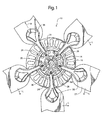
- a ceiling fan 10 having a motor housing 11 which encases an electric motor 13 connected to a source of electric power by unshown wires.
- the motor 13 includes a bottom mounting plate 14 that rotates and thereby drives an annular array of blade irons 16, each having a blade 17 mounted thereto in conventional fashion.
- the motor bottom mounting plate 14 has an annular array of threaded mounting holes 19 and a centrally positioned, raised, annular stop 20.
- Each blade iron 16 has a motor mounting flange 21 configured to be coupled with the bottom mounting plate 14 of the electric motor 13.
- the mounting flange 21 has an elongated slot 23 therethrough which is aligned with the threaded mounting hole 19 of the bottom mounting plate 14.
- a retaining member in the form of a mounting bolt or screw 24 extends through the elongated slot 23 and is threadably received in the mounting hole 19. The mounting screw 24 however allows radial and pivotal movement of the blade iron 16 relative to the bottom mounting plate 14 of the motor.
- the motor mounting flange 21 also includes a keyhole shaped hole 25.
- the ceiling fan 10 also includes an annular balancing member in the form of a balancing ring 28 positioned concentrically about the annular stop 20.
- the concentric positioning of the balancing ring allows for limited movement relative to the bottom mounting plate 14.
- the central hole 29 within the balancing ring is defined by inner walls 30 which contacts the annular stop 20 to limit the radial movement of the balancing ring 28.
- the balancing ring 28 includes an annular array of rivets 32 which are received withing the keyhole shaped hole 25 of the blade irons 16.
- the balancing ring 28 initially is centrally positioned so that the blade irons are equally spaced from the center point of the bottom mounting plate 14, as shown in Fig. 3 .
- the operation of the motor 13 rotates the motor bottom mounting plate 14, thereby rotating the blade irons 16 and blades 17, creating a centrifugal force upon each blade iron.
- the ceiling fan automatically balances itself in a manner described in more detail hereinafter.
- other factors previously recited may also cause an off-balancing of a combined blade iron and blade, for ease of description described hereinafter as simply the blade iron.
- the ceiling fan corrects this off-balancing by establishing an equilibrium balance through the subsequent relative movements of the blade irons.
- the heavier blade iron 35 moves in an outboard direction from the center of the bottom mounting plate 14 because of its relative weight.
- the outboard movement of the heavier blade iron 35 is illustrated by arrow H.
- the outboard movement of the heavier blade iron 35 forces the balancing ring 28 coupled therewith to move outboard in relatively the same direction, as illustrated by arrow R.
- the outboard movement of the balancing ring 28 in direction H causes the other blade irons 36 to pivot and/or longitudinally move in an Aopposite@ direction to the movement of the heavier blade iron 35, as indicated by arrows L.
- the term opposite is intended to denote a direction generally away from the direction of the heavier blade iron 35 eventhough such movement is not 180 degrees in the opposite direction.
- the movement of the two oppositely disposed blade irons 36 is indicated by arrows L, which is shown to be approximately 120 degrees from the direction of arrow H.
- the term opposite direction may mean a direction as little as 91 degrees offset from direction H.
- each mounting screw 24 and slot 23 establishes a first pivot about which the blade iron pivotally and radially moves relative to the motor, while the rivet 32 and keyhole shaped hole 25 establish a second pivot about which the blade iron pivotally moves relative to the balancing ring 28.
- rivets 32 may also be in the form of posts, screws, bolts, or other movement limiting means.
- stop 20 may be in the other forms such as seats, walls, flanges, posts, screws within oversized holes, or other obstructions. These stops may also be positioned within or outside of the balancing member, so long as they allow but limit radial movement of the balancing member.
Landscapes
- Engineering & Computer Science (AREA)
- Mechanical Engineering (AREA)
- General Engineering & Computer Science (AREA)
- Structures Of Non-Positive Displacement Pumps (AREA)
Applications Claiming Priority (1)
| Application Number | Priority Date | Filing Date | Title |
|---|---|---|---|
| US11/655,393 US7665970B2 (en) | 2007-01-18 | 2007-01-18 | Fan blade mounting system |
Publications (2)
| Publication Number | Publication Date |
|---|---|
| EP1947345A2 true EP1947345A2 (de) | 2008-07-23 |
| EP1947345A3 EP1947345A3 (de) | 2009-03-04 |
Family
ID=39295047
Family Applications (1)
| Application Number | Title | Priority Date | Filing Date |
|---|---|---|---|
| EP08150375A Withdrawn EP1947345A3 (de) | 2007-01-18 | 2008-01-17 | Montagesystem für Ventilatorschaufeln |
Country Status (7)
| Country | Link |
|---|---|
| US (1) | US7665970B2 (de) |
| EP (1) | EP1947345A3 (de) |
| CN (1) | CN101255872B (de) |
| BR (1) | BRPI0800056A2 (de) |
| CA (1) | CA2617306A1 (de) |
| MX (1) | MX2008000871A (de) |
| TW (1) | TW200844333A (de) |
Families Citing this family (9)
| Publication number | Priority date | Publication date | Assignee | Title |
|---|---|---|---|---|
| US8047795B2 (en) * | 2007-01-18 | 2011-11-01 | Hunter Fan Company | Fan blade mounting system |
| US7914260B2 (en) * | 2007-01-18 | 2011-03-29 | Hunter Fan Company | Fan blade mounting system |
| US20090180881A1 (en) * | 2008-01-15 | 2009-07-16 | Hunter Fan Company | Fan blade mounting system |
| US8668451B2 (en) * | 2009-09-10 | 2014-03-11 | Hunter Fan Company | Fan blade mounting system |
| US9039377B2 (en) | 2010-08-09 | 2015-05-26 | Lowe's Companies, Inc. | Fan assemblies and methods for assembling same |
| US20140271286A1 (en) * | 2013-03-14 | 2014-09-18 | William McNeill | Noise Producing Fan |
| CN105422508A (zh) * | 2015-12-31 | 2016-03-23 | 江苏富丽华通用设备有限公司 | 一种轴流风机支架结构 |
| CN109555727B (zh) * | 2019-01-07 | 2024-06-07 | 奥卡冷却系统(天津)有限公司 | 一种连接器及组合式风扇 |
| CN112065747B (zh) * | 2020-09-10 | 2022-05-17 | 江西艾斯欧匹精密智造科技有限公司 | 一种便于安装的风机 |
Family Cites Families (31)
| Publication number | Priority date | Publication date | Assignee | Title |
|---|---|---|---|---|
| US2383002A (en) | 1943-05-03 | 1945-08-21 | John Spargo | Impeller and governor for same |
| US3551070A (en) | 1968-05-08 | 1970-12-29 | Dov Z Glucksman | Axial fan |
| FR2422076A1 (fr) | 1978-04-06 | 1979-11-02 | Hispano Suiza Sa | Dispositif de reequilibrage automatique de systemes tournants |
| US4511310A (en) | 1984-03-02 | 1985-04-16 | Robbins & Myers, Inc. | Ceiling fan blade isolation |
| US4634345A (en) | 1985-03-22 | 1987-01-06 | Emerson Electric Co. | Ceiling fan mounted close to ceiling |
| USD323384S (en) | 1988-09-06 | 1992-01-21 | Casablanca Fan Company, Inc. | Ceiling fan |
| USD312688S (en) | 1988-11-29 | 1990-12-04 | Casablanca Fan Company, Inc. | Combined ceiling fan and light fixture |
| USD325776S (en) | 1990-03-22 | 1992-04-28 | Hunter Fan Company | Combined ceiling fan and light |
| USD324100S (en) | 1990-04-30 | 1992-02-18 | Casablanca Fan Company, Inc. | Ceiling fan motor housing |
| USD328947S (en) | 1991-09-19 | 1992-08-25 | Casablanca Fan Company, Inc. | Combined electric ceiling fan and light |
| US5222864A (en) | 1991-09-27 | 1993-06-29 | Hunter Fan Company | Ceiling fan |
| GB2263943B (en) | 1992-01-29 | 1996-05-08 | Hunter Fan Co | Ceiling fan |
| US5271717A (en) | 1992-01-31 | 1993-12-21 | Aisin Kako Kabushiki Kaisha | Coupling fan |
| USD346209S (en) | 1993-01-25 | 1994-04-19 | Casablanca Fan Company | Combined ceiling fan mounting canopy, motor and switch housing and blade irons unit |
| US5380156A (en) | 1993-04-12 | 1995-01-10 | Iacovino; Robert | Ceiling fan balance apparatus |
| US5304037A (en) | 1993-04-14 | 1994-04-19 | Hunter Fan Company | Ceiling fan blade vibration isolation system |
| USD349336S (en) | 1993-10-29 | 1994-08-02 | Hunter Fan Company | Ceiling fan |
| USD357978S (en) | 1993-12-03 | 1995-05-02 | Casablanca Fan Company | Combined ceiling fan and light |
| USD361377S (en) | 1993-12-20 | 1995-08-15 | Hunter Fan Company | Combined ceiling fan and light kit |
| USD354804S (en) | 1994-03-30 | 1995-01-24 | Hunter Fan Company | Ceiling fan |
| USD358877S (en) | 1994-07-07 | 1995-05-30 | Hunter Fan Company | Ceiling fan |
| US5501010A (en) | 1994-08-08 | 1996-03-26 | Eaton Corporation | Method of assembly for a fan |
| US5593283A (en) | 1994-08-08 | 1997-01-14 | Eaton Corporation | Fan and fan drive and assembly thereof |
| USD367321S (en) | 1995-04-14 | 1996-02-20 | Casablanca Fan Company | Combined motor housing and blade irons unit for an electric ceiling fan |
| US5593281A (en) | 1995-10-02 | 1997-01-14 | Jen-Lung D. Tai | Dynamic balancing apparatus for ceiling fans |
| US5944487A (en) | 1996-08-09 | 1999-08-31 | Hunter Fan Company | Blade ring attachment system |
| US6382917B1 (en) | 1999-03-03 | 2002-05-07 | Hunter Fan Company | Ceiling fan having side mounted blade irons |
| US6364612B1 (en) * | 2000-12-11 | 2002-04-02 | Tien Fu Tseng | Ceiling fan structure |
| US6857854B2 (en) | 2002-07-12 | 2005-02-22 | Hunter Fan Company | Quick connect blade system |
| US6932576B2 (en) | 2003-04-01 | 2005-08-23 | Hunter Fan Company | Quick connect ceiling fan blade |
| US6902375B2 (en) | 2003-05-01 | 2005-06-07 | Hunter Fan Company | Quick connect ceiling fan blade |
-
2007
- 2007-01-18 US US11/655,393 patent/US7665970B2/en active Active
-
2008
- 2008-01-07 CA CA002617306A patent/CA2617306A1/en not_active Abandoned
- 2008-01-15 TW TW097101507A patent/TW200844333A/zh unknown
- 2008-01-17 CN CN2008100018762A patent/CN101255872B/zh active Active
- 2008-01-17 EP EP08150375A patent/EP1947345A3/de not_active Withdrawn
- 2008-01-17 BR BRPI0800056-5A patent/BRPI0800056A2/pt not_active IP Right Cessation
- 2008-01-18 MX MX2008000871A patent/MX2008000871A/es not_active Application Discontinuation
Also Published As
| Publication number | Publication date |
|---|---|
| CN101255872B (zh) | 2012-05-30 |
| MX2008000871A (es) | 2009-02-24 |
| US7665970B2 (en) | 2010-02-23 |
| CN101255872A (zh) | 2008-09-03 |
| BRPI0800056A2 (pt) | 2008-11-18 |
| US20080175715A1 (en) | 2008-07-24 |
| TW200844333A (en) | 2008-11-16 |
| CA2617306A1 (en) | 2008-07-18 |
| EP1947345A3 (de) | 2009-03-04 |
Similar Documents
| Publication | Publication Date | Title |
|---|---|---|
| US7914260B2 (en) | Fan blade mounting system | |
| US7665970B2 (en) | Fan blade mounting system | |
| US8047795B2 (en) | Fan blade mounting system | |
| CA2587293A1 (en) | Self balancing fan | |
| EP4407188B1 (de) | Deckenventilator | |
| MX2008001302A (es) | Sistema de montaje para soportar una ensambladura de ventilador de techo. | |
| US11578735B2 (en) | Ceiling fan with mounting plate | |
| US20090180881A1 (en) | Fan blade mounting system | |
| US11118592B2 (en) | Ceiling fan with multiple blades | |
| US20160138614A1 (en) | Impeller for centrifugal fan and centrifugal fan | |
| MX2008001362A (es) | Sistema de montaje para soportar una ensambladura de ventilador de techo. | |
| US7175392B2 (en) | Ceiling fan motor with stationary shaft | |
| US20140023521A1 (en) | Furnace Air Handler Blower Assembly Utilizing a Motor Connected to an Impeller Fan that is Suspended with Mounting Arms | |
| US20080107527A1 (en) | Ceiling fan | |
| CN110274376A (zh) | 用于风叶的风叶支撑组件、风道组件及空调器 | |
| CN210637259U (zh) | 离心风机及具有其的空调器 | |
| CN210978004U (zh) | 用于单级低速悬臂结构离心鼓风机的平衡装置及鼓风机 | |
| JP2019094811A (ja) | 送風装置 | |
| JP2019094809A (ja) | 送風装置 | |
| KR20040084411A (ko) | 송풍팬 |
Legal Events
| Date | Code | Title | Description |
|---|---|---|---|
| PUAI | Public reference made under article 153(3) epc to a published international application that has entered the european phase |
Free format text: ORIGINAL CODE: 0009012 |
|
| AK | Designated contracting states |
Kind code of ref document: A2 Designated state(s): AT BE BG CH CY CZ DE DK EE ES FI FR GB GR HR HU IE IS IT LI LT LU LV MC MT NL NO PL PT RO SE SI SK TR |
|
| AX | Request for extension of the european patent |
Extension state: AL BA MK RS |
|
| PUAL | Search report despatched |
Free format text: ORIGINAL CODE: 0009013 |
|
| AK | Designated contracting states |
Kind code of ref document: A3 Designated state(s): AT BE BG CH CY CZ DE DK EE ES FI FR GB GR HR HU IE IS IT LI LT LU LV MC MT NL NO PL PT RO SE SI SK TR |
|
| AX | Request for extension of the european patent |
Extension state: AL BA MK RS |
|
| RIC1 | Information provided on ipc code assigned before grant |
Ipc: F04D 29/66 20060101ALI20090128BHEP Ipc: F04D 25/08 20060101AFI20080429BHEP |
|
| RAP1 | Party data changed (applicant data changed or rights of an application transferred) |
Owner name: HUNTER FAN COMPANY |
|
| AKX | Designation fees paid | ||
| REG | Reference to a national code |
Ref country code: DE Ref legal event code: 8566 |
|
| STAA | Information on the status of an ep patent application or granted ep patent |
Free format text: STATUS: THE APPLICATION IS DEEMED TO BE WITHDRAWN |
|
| 18D | Application deemed to be withdrawn |
Effective date: 20090905 |