EP1947362A1 - Hydraulischer einzelzylinder-stossdämpfer für ein fahrzeug - Google Patents
Hydraulischer einzelzylinder-stossdämpfer für ein fahrzeug Download PDFInfo
- Publication number
- EP1947362A1 EP1947362A1 EP06832526A EP06832526A EP1947362A1 EP 1947362 A1 EP1947362 A1 EP 1947362A1 EP 06832526 A EP06832526 A EP 06832526A EP 06832526 A EP06832526 A EP 06832526A EP 1947362 A1 EP1947362 A1 EP 1947362A1
- Authority
- EP
- European Patent Office
- Prior art keywords
- shock absorber
- piston
- vehicle
- cylinder
- spring constant
- Prior art date
- Legal status (The legal status is an assumption and is not a legal conclusion. Google has not performed a legal analysis and makes no representation as to the accuracy of the status listed.)
- Granted
Links
Images


Classifications
-
- F—MECHANICAL ENGINEERING; LIGHTING; HEATING; WEAPONS; BLASTING
- F16—ENGINEERING ELEMENTS AND UNITS; GENERAL MEASURES FOR PRODUCING AND MAINTAINING EFFECTIVE FUNCTIONING OF MACHINES OR INSTALLATIONS; THERMAL INSULATION IN GENERAL
- F16F—SPRINGS; SHOCK-ABSORBERS; MEANS FOR DAMPING VIBRATION
- F16F9/00—Springs, vibration-dampers, shock-absorbers, or similarly-constructed movement-dampers using a fluid or the equivalent as damping medium
- F16F9/32—Details
-
- F—MECHANICAL ENGINEERING; LIGHTING; HEATING; WEAPONS; BLASTING
- F16—ENGINEERING ELEMENTS AND UNITS; GENERAL MEASURES FOR PRODUCING AND MAINTAINING EFFECTIVE FUNCTIONING OF MACHINES OR INSTALLATIONS; THERMAL INSULATION IN GENERAL
- F16F—SPRINGS; SHOCK-ABSORBERS; MEANS FOR DAMPING VIBRATION
- F16F9/00—Springs, vibration-dampers, shock-absorbers, or similarly-constructed movement-dampers using a fluid or the equivalent as damping medium
- F16F9/06—Springs, vibration-dampers, shock-absorbers, or similarly-constructed movement-dampers using a fluid or the equivalent as damping medium using both gas and liquid
- F16F9/061—Mono-tubular units
-
- B—PERFORMING OPERATIONS; TRANSPORTING
- B60—VEHICLES IN GENERAL
- B60G—VEHICLE SUSPENSION ARRANGEMENTS
- B60G13/00—Resilient suspensions characterised by arrangement, location or type of vibration dampers
- B60G13/02—Resilient suspensions characterised by arrangement, location or type of vibration dampers having dampers dissipating energy, e.g. frictionally
- B60G13/06—Resilient suspensions characterised by arrangement, location or type of vibration dampers having dampers dissipating energy, e.g. frictionally of fluid type
- B60G13/08—Resilient suspensions characterised by arrangement, location or type of vibration dampers having dampers dissipating energy, e.g. frictionally of fluid type hydraulic
-
- F—MECHANICAL ENGINEERING; LIGHTING; HEATING; WEAPONS; BLASTING
- F16—ENGINEERING ELEMENTS AND UNITS; GENERAL MEASURES FOR PRODUCING AND MAINTAINING EFFECTIVE FUNCTIONING OF MACHINES OR INSTALLATIONS; THERMAL INSULATION IN GENERAL
- F16F—SPRINGS; SHOCK-ABSORBERS; MEANS FOR DAMPING VIBRATION
- F16F9/00—Springs, vibration-dampers, shock-absorbers, or similarly-constructed movement-dampers using a fluid or the equivalent as damping medium
- F16F9/32—Details
- F16F9/58—Stroke limiting stops, e.g. arranged on the piston rod outside the cylinder
- F16F9/585—Stroke limiting stops, e.g. arranged on the piston rod outside the cylinder within the cylinder, in contact with working fluid
-
- B—PERFORMING OPERATIONS; TRANSPORTING
- B60—VEHICLES IN GENERAL
- B60G—VEHICLE SUSPENSION ARRANGEMENTS
- B60G2202/00—Indexing codes relating to the type of spring, damper or actuator
- B60G2202/20—Type of damper
- B60G2202/24—Fluid damper
Definitions
- This invention relates to an improvement in a single cylinder type hydraulic shock absorber for a vehicle.
- a piston that contacts an inner peripheral surface of a cylinder slidingly is attached fixedly to a tip end portion of a rod, and an oil chamber and a gas chamber are delineated by fitting a free piston slidingly within the cylinder (see JP08-159199 ).
- a passage that connects two oil chambers delineated by the piston is provided in the piston, and an orifice or the like that applies resistance to a flow of working oil passing through the passage is interposed in the piston.
- the gas chamber compensates for variation in the volume of the cylinder occurring when the rod infiltrates the cylinder or withdraws from the cylinder.
- a pressurized gas is sealed in the gas chamber, and the gas chamber maintains the working oil in the cylinder in a constantly pressurized state.
- a pressure increase in the gas chamber may not be able to keep up with a pressure increase in a contraction side oil chamber partitioned by the free piston, and as a result, the internal pressure of the contraction side oil chamber may become equal to or greater than the internal pressure of the gas chamber.
- the free piston moves in parallel with the piston such that the volume of the contraction side oil chamber does not vary, and therefore the working oil in the contraction side oil chamber cannot flow easily into an expansion side oil chamber. As a result, the volume of the expansion side oil chamber simply expands.
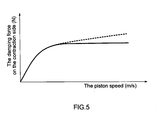
- the damping characteristic of the hydraulic shock absorber is as shown by the solid line in FIG. 5 , where the damping force on the contraction side no longer increases at or above a certain piston speed. Therefore, the damping characteristic shown by the broken line in FIG. 5 , which is required to suppress vibration in the vehicle body, cannot be realized.
- the internal pressure of the expansion side oil chamber may fall below the outside air pressure, causing outside air to be sucked into the cylinder through a gap between the rod and a sealing member provided between the rod and the cylinder. In such a case, aeration, adiabatic compression and so on may occur.
- the internal pressure of the gas chamber may be set high in advance. In so doing, however, the internal pressure of the oil chambers in the cylinder becomes higher than necessary, thereby impairing the passenger comfort of the vehicle. Moreover, the internal pressure of the oil chambers acts excessively on the sealing member, and as a result, the rod is prevented from moving smoothly, leading to a reduction in the life of the sealing member.
- This invention has been designed in consideration of the problems described above, and it is an object thereof to provide a single cylinder type hydraulic shock absorber which is capable of improving the passenger comfort of a vehicle by exhibiting a favorable damping characteristic even when a piston speed is high.
- this invention provides a single cylinder type hydraulic shock absorber for a vehicle, which is interposed between a vehicle body and an axle of a vehicle to suppress vibration in the vehicle body.
- the single cylinder type hydraulic shock absorber for a vehicle comprises a cylinder, a free piston that is inserted slidably into the cylinder and delimits a fluid chamber and a gas chamber in the cylinder, a piston that is inserted slidably into the cylinder and delimits the fluid chamber into two pressure chambers, a rod, one end of which is connected to the piston, and an elastic member that is accommodated in the gas chamber and biases the free piston in the direction of the fluid chamber, wherein the elastic member is set such that a spring constant thereof increases during contraction.
- the free piston is biased not only by an increase in the internal pressure of the gas chamber, but also by the elastic member, and therefore the interior of the fluid chamber is greatly pressurized.
- the damping force on the contraction side is prevented from peaking, and as a result, vibration in the vehicle body can be suppressed sufficiently, enabling an improvement in the passenger comfort of the vehicle.
- the spring constant of the elastic member increases during contraction, and thus the elastic member acts to supplement the biasing force that is applied to the free piston by the internal pressure of the gas chamber. Therefore, the internal pressure of the gas chamber does not need to be set high in advance, and as a result, the passenger comfort of the vehicle is not impaired.
- FIGs. 1 to 3 a single cylinder type hydraulic shock absorber for a vehicle 100 according to a first embodiment of this invention will be described.
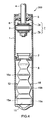
- the single cylinder type hydraulic shock absorber for a vehicle (to be referred to as a "shock absorber” hereafter) 100 is interposed between a vehicle body and an axle of a vehicle to suppress vibration in the vehicle body, and as shown in FIG. 1 , comprises a cylinder 1, a free piston 2 that is inserted slidably into the cylinder 1 and delimits a fluid chamber 7 and a gas chamber 8 in the cylinder 1, a piston 3 that is inserted slidably into the cylinder 1 and delimits the fluid chamber 7 into two pressure chambers 7a, 7b, and a rod 4, one end of which is connected to the piston 3 and another end of which extends to the exterior of the cylinder 1.
- a fluid such as working oil is charged into the expansion side pressure chamber 7a and the contraction side pressure chamber 7b. Further, a pressurized gas is sealed in the gas chamber 8, and a coil spring 9 serving as an elastic member that biases the free piston 2 in the direction of the fluid chamber 7 is accommodated in the gas chamber 8.
- the shock absorber 100 is interposed between the vehicle body and the axle via an attachment bracket (not shown) provided on an upper end of the rod 4 and a lower end of the cylinder 1.
- a passage (not shown) connecting the pressure chambers 7a and 7b is provided in the piston 3, and a damping force generating element (not shown) that applies resistance to the flow of fluid through this passage is interposed in the passage.
- the damping force generating element applies resistance to the flow of fluid.
- the shock absorber 100 generates a damping force through an expansion/contraction operation, and the damping force is determined in accordance with pressure loss generated by the damping force generating element.
- damping force generating element there are no limitations on the damping force generating element as long as it is capable of applying resistance to the flow of fluid passing through the passage so as to generate a predetermined pressure loss, and a damping valve such as an orifice or a leaf valve may be employed, for example.
- the rod 4 penetrates a sealing member 6 of an annular head member 5 that is provided in an open end of the cylinder 1 and seals the interior of the cylinder 1.
- the rod 4 extends coaxially with the cylinder 1 to the exterior of the cylinder 1.
- the gas chamber 8 is delineated on a bottom portion side of the cylinder 1, or in other words the opposite end side of the rod 4.
- the gas chamber 8 compensates for variation in the volume of the cylinder 1 occurring when the rod 4 infiltrates the cylinder 1 or withdraws from the cylinder 1. More specifically, when the shock absorber 100 expands and contracts, the free piston 2 moves such that the volume of the gas chamber 8 increases and decreases.
- the coil spring 9 comprises a small spring constant site 10 and a large spring constant site 11, and the length thereof is set such that the coil spring 9 remains in contact with the end face of the free piston 2 even when the shock absorber 100 is in a maximally expanded state and the volume of the gas chamber 8 is at a maximum.
- the free piston 2 and coil spring 9 are maintained in a state of constant contact, regardless of the expansion/contraction amount of the shock absorber 100.
- the coil spring 9 is always sandwiched between the free piston 2 and the end portion of the cylinder 1. Hence, a situation in which the free piston 2 and the coil spring 9 collide vigorously and the coil spring 9 moves violently within the cylinder 1 when the shock absorber 100 expands and contracts, is avoided. Therefore, abnormal noise generation is prevented.
- the coil spring 9 is constituted such that when it is compressed from a vertical direction, the small spring constant site 10 enters a maximally compressed state before the large spring constant site 11 deforms maximally into a maximally compressed state in which adjacent coils come into contact with each other (see FIG. 2 ).
- the spring constant of the coil spring 9 is constituted to be variable.
- the free piston 2 When the shock absorber 100 expands and contracts such that the piston 3 displaces relative to the cylinder 1, the free piston 2 also displaces by an amount obtained by dividing an infiltration volume or a withdrawal volume of the rod 4 by a pressure-receiving area of the piston 3.
- the coil spring 9 causes a spring reaction force to act on the free piston 2 at a combined spring constant that is identical to a spring constant obtained by disposing a spring having a small spring constant and a spring having a large spring constant in series.
- the coil spring 9 causes a spring reaction force to act on the free piston 2 at a large spring constant.
- the spring constant of the coil spring 9 is set to increase during contraction.
- the small spring constant site 10 is set to enter the maximally compressed state, in which adjacent coils come into contact with each other, when a stroke position of the piston 3 relative to the cylinder 1 reaches a predetermined position.
- the predetermined position is a neutral position that is the center of the stroke of the piston 3.
- the small spring constant site 10 of the coil spring 9 is in the maximally compressed state, and therefore the coil spring 9 causes a spring reaction force that is commensurate with the deformation amount of the large spring constant site 11 to act relative to the displacement of the free piston 2.
- the piston speed is typically low and therefore remains in a low speed region.
- the rod infiltration volume is small and the deformation amount of the large spring constant site 11 is also sufficiently small. Therefore, the fluid chamber 7 is not greatly pressurized by the free piston 2.
- the damping characteristic of the shock absorber 100 in the low speed region is such that the damping force is not excessively large, and therefore passenger comfort can be maintained in the vehicle.
- the piston speed typically increases into a high speed region.
- the rod infiltration volume is large and the deformation amount of the large spring constant site 11 is also large. Therefore, the free piston 2 is biased not only by the internal pressure of the gas chamber 8, but also by a large spring reaction force commensurate with the deformation amount of the coil spring 9.
- the fluid chamber 7 receives greater pressure from the free piston 2 than in a conventional shock absorber.
- the damping characteristic in the high speed region is such that the damping force is prevented from peaking, and as a result, vibration in the vehicle body can be suppressed sufficiently, enabling an improvement in passenger comfort.
- the spring constant of the coil spring 9 increases during contraction, and the resulting reaction force acts to supplement the biasing force applied to the free piston 2 by the gas pressure in the gas chamber 8.
- the free piston 2 displaces in a direction for increasing the volume of the gas chamber 8.
- the spring reaction force of the coil spring 9 corresponds to the combined spring constant of the small spring constant and the large spring constant, and is therefore sufficiently weak. Accordingly, the internal pressure of the fluid chamber 7a that is compressed during the expansion stroke can be made equal to that of a conventional shock absorber, and the resulting damping characteristic is as shown in FIG. 3 , whereby vibration in the vehicle body can be suppressed and the passenger comfort can be improved.
- the small spring constant site 10 is set to enter the maximally compressed state when the stroke position of the piston 3 is the in neutral position.
- the stroke position of the piston 3 in which the small spring constant site 10 enters the maximally compressed state may be modified appropriately in accordance with the use application of the vehicle and so on.
- the small spring constant site 10 may be set to be capable of expansion and contraction when the stroke position of the piston 3 is the in neutral position.
- the small spring constant site 10 expands and contracts during a normal operation of the vehicle, thereby causing a spring reaction force to act on the free piston 2.
- the small spring constant site 10 enters the maximally compressed state such that a spring reaction force is caused to act on the free piston 2 by the expansion and contraction of the large spring constant site 11.
- the elastic member of this embodiment is formed by disposing the single small spring constant site 10 and the single large spring constant site 11 in series.
- the elastic member may be formed by disposing a plurality of small spring constant sites and a plurality of large spring constant sites in series, for example.
- the elastic member may also be constituted by a small spring constant site and a large spring constant site disposed parallel thereto and on the outer periphery or inner periphery thereof such that the small spring constant site is constantly sandwiched between the free piston 2 and the end portion of the cylinder 1.
- the free piston 2 displaces in a direction for shrinking the gas chamber 8
- the large spring constant site comes into contact with the free piston 2.
- the shock absorber 200 differs from the shock absorber 100 of the first embodiment in the constitution of the elastic member. The following description will focus on this difference.
- An elastic member 12 of the shock absorber 200 is made of synthetic resin, and as shown in FIG. 4 , comprises a base portion 15 that is fitted to the inner periphery of the cylinder 1, and a biasing portion 16 that stands upright from the base portion 15 and contacts the end portion of the free piston 2.
- the biasing portion 16 comprises a small spring constant site 16a on its tip end side and a large spring constant site 16b on its base end side.
- the small spring constant site 16a is set to enter a maximally compressed state when the stroke position of the piston 3 relative to the cylinder 1 is in the neutral position.
- the outer diameter of the base portion 15 is set to be equal to or slightly larger than the inner diameter of the cylinder 1, and by fitting the base portion 15 into the end portion of the cylinder 1, the elastic member 12 is positioned within the cylinder 1. Further, the length of the elastic member 12 is set such that the biasing portion 16 contacts the end face of the free piston 2 even when the shock absorber 200 is in a maximally expanded state and the volume of the gas chamber 8 is at a maximum. Hence, a situation in which the free piston 2 and the elastic member 12 collide vigorously and the elastic member 12 moves violently within the cylinder 1 when the shock absorber 200 expands and contracts, is avoided. Therefore, abnormal noise generation is prevented.
- the base portion 15 is provided with a through hole 15a penetrating vertically.
- an operation to seal a gas in the gas chamber 8 can be performed through the through hole 15a.
- the elastic member 12 is constituted such that when it is compressed from a vertical direction, the small spring constant site 16a enters the maximally compressed state before the large spring constant site 16b deforms maximally into a maximally compressed state.
- the spring constant of the elastic member 12 is constituted to be variable.
- the free piston 2 When the shock absorber 200 expands and contracts such that the piston 3 displaces relative to the cylinder 1, the free piston 2 also displaces by an amount obtained by dividing the infiltration volume or withdrawal volume of the rod 4 by the pressure-receiving area of the piston 3.
- the elastic member 12 causes a spring reaction force to act on the free piston 2 at a combined spring constant that is identical to a spring constant obtained when a spring having a small spring constant and a spring having a large spring constant are disposed in series.
- the elastic member 12 when the small spring constant site 16a enters the maximally compressed state relative to the displacement of the free piston 2, the elastic member 12 causes a spring reaction force to act on the free piston 2 at a large spring constant.
- the spring constant of the elastic member 12 is set to increase during contraction.
- the shock absorber 200 constituted in the above manner exhibits similar actions and effects to the shock absorber 100 of the first embodiment.
- the free piston 2 is biased not only by the internal pressure of the gas chamber 8, but also by a large spring reaction force commensurate with the deformation amount of the elastic member 12. Hence, a situation in which the free piston 2 moves in parallel with the piston 3 is avoided even when the piston speed increases during the contraction stroke. Accordingly, the damping characteristic in the high speed region is such that the damping force is prevented from peaking, as shown in FIG. 3 .
- the spring constant of the elastic member 12 increases during contraction, and the resulting reaction force acts to supplement the biasing force applied to the free piston 2 by the gas pressure in the gas chamber 8.
- the free piston 2 displaces in a direction for increasing the volume of the gas chamber 8.
- the spring reaction force of the elastic member 12 corresponds to the combined spring constant of the small spring constant and the large spring constant, and is therefore sufficiently weak. Accordingly, the internal pressure of the fluid chamber 7a that is compressed during the expansion stroke can be made equal to that of a conventional shock absorber, and the damping characteristic is as shown in FIG. 3 , whereby vibration in the vehicle body can be suppressed and the passenger comfort can be improved.
- the elastic member 12 is made of synthetic resin, it is lighter than an elastic member such as a coil spring, and therefore a reduction in the weight of the shock absorber 200 can be achieved. Furthermore, the base portion 15 can be fitted into the lower end of the cylinder 1, and therefore positioning of the elastic member 12 relative to the cylinder 1 during an assembly operation of the shock absorber 200 is extremely easy.
- This invention may be applied to a shock absorber that is interposed between a vehicle body and an axle of a vehicle.
Landscapes
- Engineering & Computer Science (AREA)
- General Engineering & Computer Science (AREA)
- Mechanical Engineering (AREA)
- Fluid-Damping Devices (AREA)
- Vehicle Body Suspensions (AREA)
Applications Claiming Priority (2)
| Application Number | Priority Date | Filing Date | Title |
|---|---|---|---|
| JP2005323068A JP4909570B2 (ja) | 2005-11-08 | 2005-11-08 | 単筒型液圧緩衝器 |
| PCT/JP2006/322513 WO2007055342A1 (ja) | 2005-11-08 | 2006-11-07 | 車両用単筒型液圧緩衝器 |
Publications (3)
| Publication Number | Publication Date |
|---|---|
| EP1947362A1 true EP1947362A1 (de) | 2008-07-23 |
| EP1947362A4 EP1947362A4 (de) | 2009-09-16 |
| EP1947362B1 EP1947362B1 (de) | 2010-05-26 |
Family
ID=38023335
Family Applications (1)
| Application Number | Title | Priority Date | Filing Date |
|---|---|---|---|
| EP06832526A Not-in-force EP1947362B1 (de) | 2005-11-08 | 2006-11-07 | Hydraulischer einzelzylinder-stossdämpfer für ein fahrzeug |
Country Status (9)
| Country | Link |
|---|---|
| US (1) | US8448759B2 (de) |
| EP (1) | EP1947362B1 (de) |
| JP (1) | JP4909570B2 (de) |
| KR (1) | KR100914596B1 (de) |
| CN (1) | CN101305203B (de) |
| CA (1) | CA2627817C (de) |
| DE (1) | DE602006014575D1 (de) |
| ES (1) | ES2344320T3 (de) |
| WO (1) | WO2007055342A1 (de) |
Cited By (2)
| Publication number | Priority date | Publication date | Assignee | Title |
|---|---|---|---|---|
| WO2010100286A1 (de) * | 2009-03-06 | 2010-09-10 | Schunk Gmbh & Co. Kg Spann- Und Greiftechnik | Dämpfungssystem zur anschlagsdämpfung |
| WO2012156854A3 (en) * | 2011-05-03 | 2013-05-10 | Cuce Giorgio | Structure of hydraulic damper |
Families Citing this family (21)
| Publication number | Priority date | Publication date | Assignee | Title |
|---|---|---|---|---|
| US8439173B2 (en) * | 2008-09-25 | 2013-05-14 | GM Global Technology Operations LLC | Methods and apparatus for a suspension system with progressive resistance |
| JP5496485B2 (ja) * | 2008-10-03 | 2014-05-21 | 株式会社小松製作所 | 液体封入マウント |
| KR101263479B1 (ko) | 2008-12-08 | 2013-05-10 | 주식회사 만도 | 모노 튜브식 쇽업소버 |
| DE102011012730B4 (de) * | 2010-03-02 | 2021-04-29 | Hitachi Automotive Systems, Ltd. | Stoßdämpfer |
| TWM390885U (en) * | 2010-06-04 | 2010-10-21 | Sen-Xiang Zhou | Shock absorber |
| JP5485061B2 (ja) * | 2010-07-29 | 2014-05-07 | 株式会社ショーワ | 油圧緩衝器 |
| JP5789106B2 (ja) * | 2011-03-03 | 2015-10-07 | カヤバ工業株式会社 | サスペンション |
| CN102758426B (zh) * | 2011-04-28 | 2015-08-26 | 四川宏华石油设备有限公司 | 升降式平台的锁紧装置 |
| US8833877B2 (en) * | 2012-05-14 | 2014-09-16 | Bsh Home Appliances Corporation | Hinge assembly for domestic appliance |
| JP5977700B2 (ja) * | 2013-03-28 | 2016-08-24 | Kyb株式会社 | 緩衝器 |
| US10183539B2 (en) * | 2014-09-17 | 2019-01-22 | Fox Factory, Inc. | Shock absorber |
| US9662951B1 (en) * | 2016-01-06 | 2017-05-30 | Caterpillar Inc. | Truck strut fail-safe |
| DE102016123460A1 (de) * | 2016-12-05 | 2018-06-07 | Stabilus Gmbh | Kolben-Zylinder Aggregat |
| CN108468739B (zh) * | 2018-05-30 | 2024-06-04 | 浙江科技学院 | 一种筒圈式阻尼可调液压减振器 |
| CN109033708B (zh) * | 2018-08-29 | 2022-12-16 | 华南理工大学 | 一种串并联r式汽车减振器的压力损失计算方法 |
| CN109299518B (zh) * | 2018-08-29 | 2022-12-16 | 华南理工大学 | 一种串联r式汽车减振器的压力损失计算方法 |
| CN109101748B (zh) * | 2018-08-29 | 2022-12-16 | 华南理工大学 | 一种并联r式汽车减振器的压力损失计算方法 |
| CN109190240B (zh) * | 2018-08-29 | 2022-12-16 | 华南理工大学 | 一种并串联r式汽车减振器的压力损失计算方法 |
| CN109523737B (zh) * | 2018-11-14 | 2020-10-27 | 湖北博士来科技集团有限公司 | 一种消防安全自动报警装置 |
| US11466750B2 (en) * | 2019-07-25 | 2022-10-11 | The Boeing Company | Liquid-mechanical isolator |
| US11311815B1 (en) * | 2020-10-24 | 2022-04-26 | Earl Ray Trindle | Suspension shock absorber |
Family Cites Families (27)
| Publication number | Priority date | Publication date | Assignee | Title |
|---|---|---|---|---|
| DE896310C (de) | 1951-07-15 | 1953-11-12 | Albert Dillenburger | Teleskop-Stossdaempfer |
| FR1112300A (fr) * | 1954-10-08 | 1956-03-12 | Perfectionnements aux amortisseurs hydrauliques de suspension | |
| DE1163693B (de) | 1960-06-18 | 1964-02-20 | Boge Gmbh | Hydraulischer Teleskopdaempfer mit sperrbarem Stroemungsweg einer Ventilgruppe des Arbeitskolbens, insbesondere fuer Kraftfahrzeuge |
| GB1173456A (en) * | 1966-11-09 | 1969-12-10 | Kayaba Industry Co Ltd | Method and Apparatus for Sealing Gas under High Pressure into a Gas-Sealed Type Shock Absorber |
| FR1529926A (fr) * | 1967-05-12 | 1968-06-21 | Perfectionnements à l'amortissement des suspensions de véhicules | |
| JPS5037831B1 (de) | 1971-02-19 | 1975-12-05 | ||
| DE2218475A1 (de) | 1972-04-17 | 1973-10-31 | Stabilus Gmbh | Einrohrdaempfer mit druckgasfreiem arbeitsraum und abgestuetztem faltenbalg |
| US4007667A (en) * | 1975-08-15 | 1977-02-15 | Fauchon Engineering Works Limited | Hydraulic positioning and shock-absorbing apparatus |
| JPS6135796Y2 (de) * | 1980-05-08 | 1986-10-17 | ||
| JPS5845293A (ja) * | 1981-09-10 | 1983-03-16 | Idemitsu Kosan Co Ltd | 緩衝器用流体組成物 |
| JPS6334336A (ja) * | 1986-07-25 | 1988-02-15 | Kato Hatsujo Kaisha Ltd | 緩衝装置 |
| JPH0631349Y2 (ja) * | 1989-10-13 | 1994-08-22 | 株式会社フジカ | 吊下げ使用形のクラッカー |
| DE19535711C1 (de) * | 1995-09-26 | 1997-01-23 | Stabilus Gmbh | Verstellelement |
| JPH058078A (ja) | 1991-06-28 | 1993-01-19 | Mitsubishi Electric Corp | レーザ加工機 |
| JPH058078U (ja) * | 1991-07-18 | 1993-02-02 | トキコ株式会社 | ガススプリング |
| JPH08159199A (ja) | 1994-12-09 | 1996-06-18 | Showa:Kk | 油圧緩衝器のフリーピストン |
| CN2260740Y (zh) * | 1996-08-13 | 1997-08-27 | 陈宾 | 汽车碰撞阻尼减震装置 |
| US5913391A (en) * | 1997-01-09 | 1999-06-22 | Avm, Inc. | Damper |
| US5868383A (en) * | 1997-03-27 | 1999-02-09 | L&P Property Management Company | Multiple rate coil spring assembly |
| CN2353608Y (zh) * | 1998-08-25 | 1999-12-15 | 齐秉智 | 多重缓冲反冲型汽车保护器 |
| DE19916017B8 (de) * | 1999-04-09 | 2004-09-30 | Denk Engineering Gmbh | Federeinrichtung |
| DE20204321U1 (de) * | 2002-03-19 | 2002-05-29 | Leica Microsystems Ag, Heerbrugg | Federelement |
| JP2004232653A (ja) * | 2003-01-28 | 2004-08-19 | Kayaba Ind Co Ltd | 単筒型油圧緩衝器 |
| US6981578B2 (en) * | 2003-07-31 | 2006-01-03 | Troy Leiphart | Non-pressurized monotube shock absorber |
| EP1666759B1 (de) * | 2003-09-24 | 2011-07-20 | Bridgestone Corporation | Vibrationsabsorbierendes legierungsteil und gummivibrationsisolator, bodenvibrationsdämpfer, reifen, stahldraht und seismischer isolator, die dieses legierungsteil benutzen |
| US7380799B2 (en) * | 2003-11-05 | 2008-06-03 | Bfs Diversified Products, Llc | Adjustable vehicle suspension system with adjustable-rate air spring |
| SE529043C2 (sv) * | 2004-08-11 | 2007-04-17 | Oehlins Racing Ab | Arrangemang med eller i form av en gasfjäder |
-
2005
- 2005-11-08 JP JP2005323068A patent/JP4909570B2/ja not_active Expired - Fee Related
-
2006
- 2006-11-07 KR KR1020087009045A patent/KR100914596B1/ko not_active Expired - Fee Related
- 2006-11-07 EP EP06832526A patent/EP1947362B1/de not_active Not-in-force
- 2006-11-07 ES ES06832526T patent/ES2344320T3/es active Active
- 2006-11-07 CA CA2627817A patent/CA2627817C/en not_active Expired - Fee Related
- 2006-11-07 WO PCT/JP2006/322513 patent/WO2007055342A1/ja not_active Ceased
- 2006-11-07 DE DE602006014575T patent/DE602006014575D1/de active Active
- 2006-11-07 CN CN2006800417371A patent/CN101305203B/zh not_active Expired - Fee Related
- 2006-11-07 US US12/084,653 patent/US8448759B2/en not_active Expired - Fee Related
Cited By (3)
| Publication number | Priority date | Publication date | Assignee | Title |
|---|---|---|---|---|
| WO2010100286A1 (de) * | 2009-03-06 | 2010-09-10 | Schunk Gmbh & Co. Kg Spann- Und Greiftechnik | Dämpfungssystem zur anschlagsdämpfung |
| DE202010017769U1 (de) | 2009-03-06 | 2012-08-03 | Schunk Gmbh & Co. Kg | Dämpfungssystem zur Anschlagdämpfung |
| WO2012156854A3 (en) * | 2011-05-03 | 2013-05-10 | Cuce Giorgio | Structure of hydraulic damper |
Also Published As
| Publication number | Publication date |
|---|---|
| WO2007055342A1 (ja) | 2007-05-18 |
| EP1947362B1 (de) | 2010-05-26 |
| CA2627817C (en) | 2011-03-15 |
| KR20080045760A (ko) | 2008-05-23 |
| ES2344320T3 (es) | 2010-08-24 |
| JP4909570B2 (ja) | 2012-04-04 |
| KR100914596B1 (ko) | 2009-08-31 |
| EP1947362A4 (de) | 2009-09-16 |
| DE602006014575D1 (de) | 2010-07-08 |
| US20090107783A1 (en) | 2009-04-30 |
| CN101305203A (zh) | 2008-11-12 |
| US8448759B2 (en) | 2013-05-28 |
| JP2007132359A (ja) | 2007-05-31 |
| CA2627817A1 (en) | 2007-05-18 |
| CN101305203B (zh) | 2010-05-19 |
Similar Documents
| Publication | Publication Date | Title |
|---|---|---|
| EP1947362B1 (de) | Hydraulischer einzelzylinder-stossdämpfer für ein fahrzeug | |
| JP5008667B2 (ja) | 非対称吸込減衰弁 | |
| CN100422591C (zh) | 与行程相关的旁路 | |
| JP2008267489A (ja) | 流体圧緩衝器 | |
| JP6374701B2 (ja) | 緩衝器 | |
| EP2587087A2 (de) | Hydraulischer Stoßdämpfer | |
| EP2565490B1 (de) | Vorderradgabel | |
| US8342303B2 (en) | Valve apparatus | |
| JP4453000B2 (ja) | 油圧緩衝器 | |
| JP2017187109A (ja) | 緩衝器 | |
| JP2017187110A (ja) | 緩衝器及び緩衝器の製造方法 | |
| EP3333446B1 (de) | Ventilanordnung für dämpfer | |
| JP2013204792A (ja) | 緩衝器 | |
| JP2006177531A (ja) | 油圧緩衝器 | |
| JP6255249B2 (ja) | ショックアブソーバ | |
| EP1555199B1 (de) | Motorradvorderradgabel | |
| JP2007120726A (ja) | 油圧緩衝器 | |
| JP2001295877A (ja) | ショックアブソーバ | |
| JP2009078721A (ja) | 油圧緩衝器 | |
| JP2018054020A (ja) | ショックアブソーバ | |
| JP4761466B2 (ja) | 空圧緩衝器 | |
| US20250305553A1 (en) | Hydraulic bump stop | |
| JP5106321B2 (ja) | 単筒型液圧緩衝器 | |
| JP4683626B2 (ja) | アキュムレータ | |
| JP2005195046A (ja) | シリンダ装置 |
Legal Events
| Date | Code | Title | Description |
|---|---|---|---|
| PUAI | Public reference made under article 153(3) epc to a published international application that has entered the european phase |
Free format text: ORIGINAL CODE: 0009012 |
|
| 17P | Request for examination filed |
Effective date: 20080508 |
|
| AK | Designated contracting states |
Kind code of ref document: A1 Designated state(s): CZ DE ES FR GB |
|
| DAX | Request for extension of the european patent (deleted) | ||
| RBV | Designated contracting states (corrected) |
Designated state(s): CZ DE ES FR GB |
|
| A4 | Supplementary search report drawn up and despatched |
Effective date: 20090817 |
|
| GRAP | Despatch of communication of intention to grant a patent |
Free format text: ORIGINAL CODE: EPIDOSNIGR1 |
|
| GRAS | Grant fee paid |
Free format text: ORIGINAL CODE: EPIDOSNIGR3 |
|
| GRAA | (expected) grant |
Free format text: ORIGINAL CODE: 0009210 |
|
| AK | Designated contracting states |
Kind code of ref document: B1 Designated state(s): CZ DE ES FR GB |
|
| REG | Reference to a national code |
Ref country code: GB Ref legal event code: FG4D |
|
| REF | Corresponds to: |
Ref document number: 602006014575 Country of ref document: DE Date of ref document: 20100708 Kind code of ref document: P |
|
| REG | Reference to a national code |
Ref country code: ES Ref legal event code: FG2A Ref document number: 2344320 Country of ref document: ES Kind code of ref document: T3 |
|
| PLBI | Opposition filed |
Free format text: ORIGINAL CODE: 0009260 |
|
| PLAX | Notice of opposition and request to file observation + time limit sent |
Free format text: ORIGINAL CODE: EPIDOSNOBS2 |
|
| 26 | Opposition filed |
Opponent name: ZF FRIEDRICHSHAFEN AG Effective date: 20110224 |
|
| REG | Reference to a national code |
Ref country code: DE Ref legal event code: R026 Ref document number: 602006014575 Country of ref document: DE Effective date: 20110224 |
|
| PLBB | Reply of patent proprietor to notice(s) of opposition received |
Free format text: ORIGINAL CODE: EPIDOSNOBS3 |
|
| PLCK | Communication despatched that opposition was rejected |
Free format text: ORIGINAL CODE: EPIDOSNREJ1 |
|
| PLBN | Opposition rejected |
Free format text: ORIGINAL CODE: 0009273 |
|
| STAA | Information on the status of an ep patent application or granted ep patent |
Free format text: STATUS: OPPOSITION REJECTED |
|
| 27O | Opposition rejected |
Effective date: 20120807 |
|
| REG | Reference to a national code |
Ref country code: DE Ref legal event code: R100 Ref document number: 602006014575 Country of ref document: DE Effective date: 20120807 |
|
| REG | Reference to a national code |
Ref country code: FR Ref legal event code: PLFP Year of fee payment: 10 |
|
| REG | Reference to a national code |
Ref country code: DE Ref legal event code: R082 Ref document number: 602006014575 Country of ref document: DE Representative=s name: GRUENECKER PATENT- UND RECHTSANWAELTE PARTG MB, DE Ref country code: DE Ref legal event code: R081 Ref document number: 602006014575 Country of ref document: DE Owner name: KYB CORPORATION, JP Free format text: FORMER OWNER: KAYABA INDUSTRY CO., LTD., TOKYO, JP |
|
| REG | Reference to a national code |
Ref country code: ES Ref legal event code: PC2A Owner name: KYB CORPORATION Effective date: 20160226 |
|
| REG | Reference to a national code |
Ref country code: FR Ref legal event code: CA Effective date: 20160321 Ref country code: FR Ref legal event code: CD Owner name: KYB CORPORATION, JP Effective date: 20160321 |
|
| REG | Reference to a national code |
Ref country code: FR Ref legal event code: PLFP Year of fee payment: 11 |
|
| REG | Reference to a national code |
Ref country code: FR Ref legal event code: PLFP Year of fee payment: 12 |
|
| PGFP | Annual fee paid to national office [announced via postgrant information from national office to epo] |
Ref country code: SE Payment date: 20181128 Year of fee payment: 8 |
|
| PGFP | Annual fee paid to national office [announced via postgrant information from national office to epo] |
Ref country code: GB Payment date: 20181120 Year of fee payment: 13 Ref country code: ES Payment date: 20181218 Year of fee payment: 13 Ref country code: FR Payment date: 20181123 Year of fee payment: 13 |
|
| PGFP | Annual fee paid to national office [announced via postgrant information from national office to epo] |
Ref country code: DE Payment date: 20191121 Year of fee payment: 14 |
|
| PG25 | Lapsed in a contracting state [announced via postgrant information from national office to epo] |
Ref country code: CZ Free format text: LAPSE BECAUSE OF NON-PAYMENT OF DUE FEES Effective date: 20191107 |
|
| GBPC | Gb: european patent ceased through non-payment of renewal fee |
Effective date: 20191107 |
|
| PG25 | Lapsed in a contracting state [announced via postgrant information from national office to epo] |
Ref country code: GB Free format text: LAPSE BECAUSE OF NON-PAYMENT OF DUE FEES Effective date: 20191107 |
|
| REG | Reference to a national code |
Ref country code: ES Ref legal event code: FD2A Effective date: 20210414 |
|
| REG | Reference to a national code |
Ref country code: DE Ref legal event code: R119 Ref document number: 602006014575 Country of ref document: DE |
|
| PG25 | Lapsed in a contracting state [announced via postgrant information from national office to epo] |
Ref country code: FR Free format text: LAPSE BECAUSE OF NON-PAYMENT OF DUE FEES Effective date: 20191202 |
|
| PG25 | Lapsed in a contracting state [announced via postgrant information from national office to epo] |
Ref country code: ES Free format text: LAPSE BECAUSE OF NON-PAYMENT OF DUE FEES Effective date: 20191108 |
|
| PG25 | Lapsed in a contracting state [announced via postgrant information from national office to epo] |
Ref country code: DE Free format text: LAPSE BECAUSE OF NON-PAYMENT OF DUE FEES Effective date: 20210601 |