EP1947376A2 - Hermetisches Kühlmittelteil - Google Patents
Hermetisches Kühlmittelteil Download PDFInfo
- Publication number
- EP1947376A2 EP1947376A2 EP07122528A EP07122528A EP1947376A2 EP 1947376 A2 EP1947376 A2 EP 1947376A2 EP 07122528 A EP07122528 A EP 07122528A EP 07122528 A EP07122528 A EP 07122528A EP 1947376 A2 EP1947376 A2 EP 1947376A2
- Authority
- EP
- European Patent Office
- Prior art keywords
- insert
- pipe
- socket
- radius
- sockets
- Prior art date
- Legal status (The legal status is an assumption and is not a legal conclusion. Google has not performed a legal analysis and makes no representation as to the accuracy of the status listed.)
- Withdrawn
Links
- 239000003507 refrigerant Substances 0.000 title description 5
- 230000008878 coupling Effects 0.000 claims abstract description 14
- 238000010168 coupling process Methods 0.000 claims abstract description 14
- 238000005859 coupling reaction Methods 0.000 claims abstract description 14
- 239000000463 material Substances 0.000 claims description 10
- 238000003780 insertion Methods 0.000 claims description 3
- 230000037431 insertion Effects 0.000 claims description 3
- 210000003739 neck Anatomy 0.000 abstract description 10
- 239000012530 fluid Substances 0.000 description 4
- 238000004519 manufacturing process Methods 0.000 description 3
- 239000002184 metal Substances 0.000 description 3
- 238000007789 sealing Methods 0.000 description 3
- 238000004378 air conditioning Methods 0.000 description 2
- 230000005489 elastic deformation Effects 0.000 description 1
- 238000000034 method Methods 0.000 description 1
- 238000012986 modification Methods 0.000 description 1
- 230000004048 modification Effects 0.000 description 1
- 238000012546 transfer Methods 0.000 description 1
Images

Classifications
-
- F—MECHANICAL ENGINEERING; LIGHTING; HEATING; WEAPONS; BLASTING
- F16—ENGINEERING ELEMENTS AND UNITS; GENERAL MEASURES FOR PRODUCING AND MAINTAINING EFFECTIVE FUNCTIONING OF MACHINES OR INSTALLATIONS; THERMAL INSULATION IN GENERAL
- F16L—PIPES; JOINTS OR FITTINGS FOR PIPES; SUPPORTS FOR PIPES, CABLES OR PROTECTIVE TUBING; MEANS FOR THERMAL INSULATION IN GENERAL
- F16L23/00—Flanged joints
- F16L23/02—Flanged joints the flanges being connected by members tensioned axially
- F16L23/024—Flanged joints the flanges being connected by members tensioned axially characterised by how the flanges are joined to, or form an extension of, the pipes
- F16L23/028—Flanged joints the flanges being connected by members tensioned axially characterised by how the flanges are joined to, or form an extension of, the pipes the flanges being held against a shoulder
- F16L23/0283—Flanged joints the flanges being connected by members tensioned axially characterised by how the flanges are joined to, or form an extension of, the pipes the flanges being held against a shoulder the collar being integral with the pipe
-
- F—MECHANICAL ENGINEERING; LIGHTING; HEATING; WEAPONS; BLASTING
- F16—ENGINEERING ELEMENTS AND UNITS; GENERAL MEASURES FOR PRODUCING AND MAINTAINING EFFECTIVE FUNCTIONING OF MACHINES OR INSTALLATIONS; THERMAL INSULATION IN GENERAL
- F16L—PIPES; JOINTS OR FITTINGS FOR PIPES; SUPPORTS FOR PIPES, CABLES OR PROTECTIVE TUBING; MEANS FOR THERMAL INSULATION IN GENERAL
- F16L23/00—Flanged joints
- F16L23/16—Flanged joints characterised by the sealing means
- F16L23/18—Flanged joints characterised by the sealing means the sealing means being rings
Definitions
- a pipe coupling assembly connects a first pipe to a second pipe.
- elastomeric seal properties degrade or exhibit excessive fluid/refrigerant emission.
- A/C air conditioning
- CO2 A/C system typically has refrigerant temperatures exceeding 300 degrees F and pressures exceeding 2000 PSIG. These conditions exceed the capabilities of elastomeric seals.
- pipe fittings examples include U.S. Pat. 5,332,267 to Harrison , U.S. Pat. 5,362,229 to Yamaga , U.S. Pat. No. 4,928,998 to Brandener , and U.S. Pat. 4,343,499 to Dumar, Jr. et al.
- the Harrison patent teaches a pipe coupling assembly for connecting a first pipe having a socket to a second pipe.
- the end of the second pipe is spherical and has a flow passage with a diameter slightly less than the diameter of the pipe to accommodate misaligning.
- the second pipe forms the coupling and is inserted into the first pipe and a clamping mechanism is disposed over the pipes.
- a ferrule is disposed between the first pipe and the clamping mechanism forming two contact areas in order to deform the socket of the first pipe to contact the surface of the second pipe.
- Initial contact of the flared surface of the first pipe and the spherical surface of the second pipe is along a line of contact, as distinguished from surface contact.
- the clamping mechanism compresses on the first pipe forcing the flared surface of the first pipe to conform about the line of contact and into the spherical surface of the second pipe to increase the contact from the line to a sealing land of definitive width, i.e., a band of contact.
- the Yamaga patent discloses a pipe coupling assembly including a first pipe having a socket and a second pipe having a spherical-shaped end and a flow passage.
- the second pipe forms the coupling and is inserted into the socket of the first pipe and secured using a clamping mechanism.
- An o-ring in conjunction with a groove on the socket of the first pipe forms a seal between the first pipe and the second pipe.
- the invention provides for a first pipe and a second pipe each having an end extending radially outwardly into a hemispherical socket.
- An insert having a bulbous shape engages the sockets of the pipes and defines a flow passage extending along an axis between the pipes.
- a clamping mechanism is disposed about the pipes for holding the sockets into engagement with the insert.
- the insert has a first neck extending axially around the flow passage and fitting into the first pipe and a second neck extending axially around the flow passage and fitting into the second pipe for substantially aligning the pipes with the axis.
- the present invention overcomes the shortcomings of relying on elastomeric seals and also allows re-use by creating a unique metal-to-metal seal geometry staying within the metal's elastic limits. Furthermore, the invention does not require threaded parts or o-rings. Also, because the ends of each pipe can be identical, it reduces manufacturing costs by allowing for the use of identical pipe ends as well as a minimum number of components. Moreover, the invention self aligns the insert with the two pipes while allowing for small movement between the two pipes within the elastic limit of the insert material. Additionally, the assembly provides unrestricted flow therethrough by providing a substantially uniform diameter, and thus cross-sectional area, between the pipes and the insert.
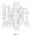
- Figure 1 is a cross-sectional view of one embodiment of the invention illustrating the insert aligned in both pipes and one bolt in the clamping mechanism;
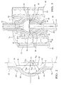
- Figure 2 is an enlarged view of Figure 1 illustrating greater socket radii than insert radii exaggerated for illustrative purposes;
- Figure 3 is a perspective view in cross-section of a second embodiment of the invention illustrating a slot in the insert.
- Figure 4 is a top view of the embodiment shown in Figure 2 illustrating the clamping mechanism.
- a first pipe 20 has an end which extends radially outwardly into an enlarged first collar 22 and then into a first hemispherical socket 24 having a first socket radius R S1
- a second pipe 26 has an end which extends radially outwardly into an enlarged second collar 28 and then into a second hemispherical socket 30 having a second socket radius R S2 .
- the first and second pipes 20, 26 are identical in shape and size to one another and the first and second sockets 24, 30 are identical in shape and size, i.e., the first socket radius R S1 is equal to the second socket radius R S2 .
- the first and second collars 22, 28 are identical in shape and size to one another, thus requiring one tool to form the sockets 24, 30 on each pipe, lowering the cost of manufacturing the assembly.
- the assembly includes an insert 32, generally indicated, having a bulbous, or nearly spherical shape, e.g., an apple shape, for engaging the sockets 24, 30 of the pipes 20, 26.
- the insert 32 is bulbous to accommodate some misalignment of the insert 32 relative to the pipes 20, 26 without changing the contact area or, more importantly, the sealing function.
- the insert 32 defines a flow passage 34 extending along an axis A between the pipes 20, 26.
- the insert 32 has a center diameter d about the axis A with a first hemisphere 36 having a first insert radius R I1 on one side of the diameter d and a second hemisphere 38 having a second insert radius R I2 on the other side of the diameter d.
- the first insert radius R I1 is equal to the second insert radius R I2 .
- the first socket radius R S1 is greater than the first insert radius R I1 and the second socket radius R S2 is greater than the second insert radius R I2 such that insertion of each of the hemispheres 36, 38 of the insert 32 into each of the respective sockets 24, 30 forms a circular contact line between each of the sockets 24, 30 and the insert 32, e.g., a latitude line.
- the difference between each socket radius R S1 , R S2 and the corresponding insert radius R I1 , R I2 directly depends on the elastic limit of the materials used. If the materials of the insert 32 and the pipes 20, 26 have higher elastic limits the difference between the radii may be greater. Similarly, if the materials have lower elastic limits, the difference between the radii must be smaller to avoid plastic deformation.
- a clamping mechanism 40 is disposed about the pipes 20, 26 for holding the sockets 24, 30 into engagement with the insert 32.
- the clamping mechanism 40 includes a first block 42 disposed about the first pipe 20 and a second block 44 disposed about the second pipe 26.
- Each of the blocks 42, 44 includes a clamping ring 46 extending circumferentially about the clamping portion 48 and defining a plurality of holes 50 extending axially.
- Each of the blocks 42, 44 of the clamping mechanism 40 includes a throat portion 52 having a diameter smaller than the collars 22, 28 and axially engaging one of the collars 22, 28 and a spherical clamping portion 48 extending from the throat portion 52 and about one of the sockets 24, 30.
- the throat portion 52 and the spherical clamping portion 48 of each block profile each of the pipes 20, 26 leaving a small space between the throat portion 52 of the blocks 42, 44 and the collars 22, 28 of the pipes 20, 26 in order to evenly transfer the load from the clamping mechanism 40 to the perimeter of the sockets 24, 30 of the pipes 20, 26.
- Each of the blocks 42, 44 defines an annular recess 54 extending axially thereinto between the clamping portion 48 and the clamping ring 46 for allowing a small amount of movement of the clamping ring 46 relative to the throat portion 52.
- the clamping mechanism 40 includes a plurality of bolts 56 disposed in the holes 50 in the clamping ring 46 of the blocks 42, 44 for clamping the first block 42 to the second block 44.
- the bolts 56 move the sockets 24, 30 into engagement with the insert 32 along the line contact between each of the hemispheres 36, 38 and each of the sockets 24, 30 as the blocks 42, 44 are moved together.
- the geometry of the contact area remains a line while the blocks 42, 44 move together, however, in practice, the surface of the insert 32 is matched closely to that of the pipe so that it produces a contact band, with the highest load at the center, due to elastic deformation of the pipe and the insert 32 adjacent to this line of contact.
- a layer of polymeric material may be disposed on the hemispheres 36, 38 of the insert 32 for forming a seal between the insert 32 and the sockets 24, 30 by filling surface imperfections in the insert 32 and the sockets 24, 30.
- the polymeric material may be coated on the surface of the insert 32 or the insert 32 may be impregnated with the polymeric material.
- the assembly is distinguished by the insert 32 having a first neck 58 extending axially around the flow passage 34 and terminating in a chamfered end and a second neck 60 extending axially around the flow passage 34 and terminating in a chamfered end.
- the first neck 58 fits with loose clearance into the first collar 22 of the first pipe 20 and the second neck 60 fits with loose clearance into the second collar 28 of the second pipe 26 to substantially align the pipes 20, 26 with the axis A.
- a small space is provided between the chamfered ends of the necks 58, 60 and each of the collars 22, 28.
- first and second necks 58, 60 may be inserted into the first and second pipes 20, 26 respectively, the necks 58, 60 are preferably inserted into the first and second collars 22, 28 so that the inside diameters of the pipes 20, 26 are substantially equal to the diameter of the flow passage 34, thus creating unrestricted flow through the assembly.
- the insert 32 defines a slot 62 extending radially and circumferentially about the axis A on the diameter d of the insert 32 for allowing movement of the first hemisphere 36 relative to the second hemisphere 38.
- the slot 62 is U-shaped and provides increased compliance allowing more deflection between the two hemispheres 36, 38 within elastic limits and increases the assembly's tolerance of thermal expansion and vibration inputs.
- the slot 62 may also allow small movement between the first pipe 20 and the second pipe 26 without causing sliding between the insert 32 and the sockets 24, 30, reducing wear or galling and subsequent leakage.
Landscapes
- Engineering & Computer Science (AREA)
- General Engineering & Computer Science (AREA)
- Mechanical Engineering (AREA)
- Quick-Acting Or Multi-Walled Pipe Joints (AREA)
Applications Claiming Priority (1)
| Application Number | Priority Date | Filing Date | Title |
|---|---|---|---|
| US11/653,704 US20080169647A1 (en) | 2007-01-16 | 2007-01-16 | Hermetic refrigerant fitting |
Publications (2)
| Publication Number | Publication Date |
|---|---|
| EP1947376A2 true EP1947376A2 (de) | 2008-07-23 |
| EP1947376A3 EP1947376A3 (de) | 2017-03-22 |
Family
ID=39430782
Family Applications (1)
| Application Number | Title | Priority Date | Filing Date |
|---|---|---|---|
| EP07122528.8A Withdrawn EP1947376A3 (de) | 2007-01-16 | 2007-12-06 | Hermetisches Kühlmittelteil |
Country Status (2)
| Country | Link |
|---|---|
| US (1) | US20080169647A1 (de) |
| EP (1) | EP1947376A3 (de) |
Families Citing this family (1)
| Publication number | Priority date | Publication date | Assignee | Title |
|---|---|---|---|---|
| CN117072780B (zh) * | 2023-10-13 | 2024-01-02 | 常州泰润塑业有限公司 | 一种密封装置及使用该装置的吹塑系统、方法 |
Citations (4)
| Publication number | Priority date | Publication date | Assignee | Title |
|---|---|---|---|---|
| US4343499A (en) | 1980-06-16 | 1982-08-10 | The Boeing Company | Ball joint flexible wear ring and seal |
| US4928998A (en) | 1988-04-12 | 1990-05-29 | Societe Jacques Dubois | Flexible exhaust coupling |
| US5332267A (en) | 1993-07-15 | 1994-07-26 | Harrison Donald G | Tube coupling |
| US5362229A (en) | 1992-06-22 | 1994-11-08 | Tokyo Electron Kabushiki Kaisha | Piping connection device |
Family Cites Families (16)
| Publication number | Priority date | Publication date | Assignee | Title |
|---|---|---|---|---|
| US2000726A (en) * | 1934-05-21 | 1935-05-07 | Jay J Weber | Train automatic air connecter |
| US3392995A (en) * | 1966-08-23 | 1968-07-16 | Malan Vibrator Co Inc | Pressure balanced ball joint |
| US3507506A (en) * | 1967-09-12 | 1970-04-21 | Cassius L Tillman | Pipe joint seal |
| US3628815A (en) * | 1970-05-04 | 1971-12-21 | Louis T King | Conduit connection means |
| CH555022A (de) * | 1972-08-10 | 1974-10-15 | Oetiker Hans | Rohrverbindung. |
| US3848899A (en) * | 1973-02-16 | 1974-11-19 | Dumont Aviat Ass | Pneumatic swivel assembly |
| US4098527A (en) * | 1977-01-21 | 1978-07-04 | Murdock Machine & Engineering Company | Tension bearing connector |
| DE2911448C2 (de) * | 1979-03-23 | 1984-05-24 | Rheinmetall GmbH, 4000 Düsseldorf | Rohrverbindung |
| AU564376B2 (en) * | 1982-08-26 | 1987-08-13 | Simplex-Ge Ltd. | Coupling device |
| FR2591293B1 (fr) * | 1985-12-11 | 1989-09-01 | Inst Francais Du Petrole | Support elastique a rotule adapte en particulier a des utilisations pour des navires ou des plates-formes flottantes en mer. |
| US4840409A (en) * | 1988-05-05 | 1989-06-20 | Taper-Lok Corporation | Swivel flow line connector |
| IT1244025B (it) * | 1990-11-23 | 1994-06-28 | Tdi Tubi Dalmine Ilva Srl | Giunto a bicchiere per tubazioni metalliche particolarmente per fluidi |
| US6003604A (en) * | 1998-04-09 | 1999-12-21 | Kraerner Oilfield Products | Subsea wellhead connection assembly and method of installation |
| US6113157A (en) * | 1998-04-09 | 2000-09-05 | Kvaerner Oilfield Products | Adjustable ball joint connector |
| DE20220520U1 (de) * | 2002-01-17 | 2003-09-11 | S.M.A. Metalltechnik GmbH & Co. KG, 71522 Backnang | Rohrverbindung |
| DE10245477A1 (de) * | 2002-09-30 | 2004-04-08 | Valeo Klimasysteme Gmbh | Muffe für CO2-Leitung |
-
2007
- 2007-01-16 US US11/653,704 patent/US20080169647A1/en not_active Abandoned
- 2007-12-06 EP EP07122528.8A patent/EP1947376A3/de not_active Withdrawn
Patent Citations (4)
| Publication number | Priority date | Publication date | Assignee | Title |
|---|---|---|---|---|
| US4343499A (en) | 1980-06-16 | 1982-08-10 | The Boeing Company | Ball joint flexible wear ring and seal |
| US4928998A (en) | 1988-04-12 | 1990-05-29 | Societe Jacques Dubois | Flexible exhaust coupling |
| US5362229A (en) | 1992-06-22 | 1994-11-08 | Tokyo Electron Kabushiki Kaisha | Piping connection device |
| US5332267A (en) | 1993-07-15 | 1994-07-26 | Harrison Donald G | Tube coupling |
Also Published As
| Publication number | Publication date |
|---|---|
| EP1947376A3 (de) | 2017-03-22 |
| US20080169647A1 (en) | 2008-07-17 |
Similar Documents
| Publication | Publication Date | Title |
|---|---|---|
| US6869080B2 (en) | Metal-to-metal sealing system | |
| US20100327579A1 (en) | Fluid fitting | |
| JP2016534303A (ja) | 管継手 | |
| JPH0160713B2 (de) | ||
| US20060214422A1 (en) | Pipe coupling retainer with axial support members | |
| EP3521677B1 (de) | Rohrverbindung und verbindungsvorrichtung | |
| AU2021244275A1 (en) | Ball joint seal | |
| US20160258560A1 (en) | Joint for high-pressure pipes and joint structure | |
| US5379798A (en) | Hydraulic coupling | |
| US8888144B2 (en) | Misalignment connector utilizing interleaved bearings | |
| EP0727026A1 (de) | Rohrverbindung | |
| EP1947376A2 (de) | Hermetisches Kühlmittelteil | |
| EP2181283B1 (de) | Einschiebbarer adapter | |
| US7273237B1 (en) | Union coupler assembly for coolant lines | |
| JP5722645B2 (ja) | 継手構造 | |
| US20060125236A1 (en) | Retainer with inward projections | |
| CN110274100A (zh) | 一种发动机管路快速连接器 | |
| JP2008501894A (ja) | 接続装置 | |
| CN214119286U (zh) | 管路连接结构 | |
| CN223768332U (zh) | 一种套管快接密封结构 | |
| KR20070058876A (ko) | 오링 수용체 | |
| US8944472B2 (en) | Conduit joint and seal ring | |
| EP4291814B1 (de) | Rohrkupplung | |
| RU2290559C2 (ru) | Самоуплотняющееся соединение трубопроводов | |
| JP2020506351A (ja) | 液圧ホース修理クランプ |
Legal Events
| Date | Code | Title | Description |
|---|---|---|---|
| PUAI | Public reference made under article 153(3) epc to a published international application that has entered the european phase |
Free format text: ORIGINAL CODE: 0009012 |
|
| AK | Designated contracting states |
Kind code of ref document: A2 Designated state(s): AT BE BG CH CY CZ DE DK EE ES FI FR GB GR HU IE IS IT LI LT LU LV MC MT NL PL PT RO SE SI SK TR |
|
| AX | Request for extension of the european patent |
Extension state: AL BA HR MK RS |
|
| RAP1 | Party data changed (applicant data changed or rights of an application transferred) |
Owner name: MAHLE INTERNATIONAL GMBH |
|
| PUAL | Search report despatched |
Free format text: ORIGINAL CODE: 0009013 |
|
| AK | Designated contracting states |
Kind code of ref document: A3 Designated state(s): AT BE BG CH CY CZ DE DK EE ES FI FR GB GR HU IE IS IT LI LT LU LV MC MT NL PL PT RO SE SI SK TR |
|
| AX | Request for extension of the european patent |
Extension state: AL BA HR MK RS |
|
| RIC1 | Information provided on ipc code assigned before grant |
Ipc: F16L 23/028 20060101AFI20170213BHEP Ipc: F16L 23/18 20060101ALI20170213BHEP |
|
| 17P | Request for examination filed |
Effective date: 20170921 |
|
| RBV | Designated contracting states (corrected) |
Designated state(s): AT BE BG CH CY CZ DE DK EE ES FI FR GB GR HU IE IS IT LI LT LU LV MC MT NL PL PT RO SE SI SK TR |
|
| AKX | Designation fees paid |
Designated state(s): AT BE BG CH CY CZ DE DK EE ES FI FR GB GR HU IE IS IT LI LT LU LV MC MT NL PL PT RO SE SI SK TR |
|
| AXX | Extension fees paid |
Extension state: MK Extension state: HR Extension state: BA Extension state: RS Extension state: AL |
|
| 17Q | First examination report despatched |
Effective date: 20180301 |
|
| GRAP | Despatch of communication of intention to grant a patent |
Free format text: ORIGINAL CODE: EPIDOSNIGR1 |
|
| INTG | Intention to grant announced |
Effective date: 20181204 |
|
| STAA | Information on the status of an ep patent application or granted ep patent |
Free format text: STATUS: THE APPLICATION IS DEEMED TO BE WITHDRAWN |
|
| 18D | Application deemed to be withdrawn |
Effective date: 20190416 |