EP1947429A2 - Procédé destiné à la commande d'un dispositif de détermination capacitive et/ou de surveillance d'une grandeur de processus - Google Patents
Procédé destiné à la commande d'un dispositif de détermination capacitive et/ou de surveillance d'une grandeur de processus Download PDFInfo
- Publication number
- EP1947429A2 EP1947429A2 EP07123857A EP07123857A EP1947429A2 EP 1947429 A2 EP1947429 A2 EP 1947429A2 EP 07123857 A EP07123857 A EP 07123857A EP 07123857 A EP07123857 A EP 07123857A EP 1947429 A2 EP1947429 A2 EP 1947429A2
- Authority
- EP
- European Patent Office
- Prior art keywords
- electrode
- signal
- probe
- response signal
- test signal
- Prior art date
- Legal status (The legal status is an assumption and is not a legal conclusion. Google has not performed a legal analysis and makes no representation as to the accuracy of the status listed.)
- Granted
Links
- 238000000034 method Methods 0.000 title claims abstract description 25
- 238000012544 monitoring process Methods 0.000 title claims abstract description 13
- 238000005259 measurement Methods 0.000 title description 23
- 239000000523 sample Substances 0.000 claims abstract description 106
- 238000012360 testing method Methods 0.000 claims abstract description 48
- 238000004519 manufacturing process Methods 0.000 claims description 4
- 238000009434 installation Methods 0.000 claims description 2
- 230000002123 temporal effect Effects 0.000 claims description 2
- 238000009413 insulation Methods 0.000 description 7
- 230000005284 excitation Effects 0.000 description 6
- 239000003990 capacitor Substances 0.000 description 5
- 238000013459 approach Methods 0.000 description 3
- 230000001419 dependent effect Effects 0.000 description 3
- 239000013590 bulk material Substances 0.000 description 2
- 238000013461 design Methods 0.000 description 2
- 230000000694 effects Effects 0.000 description 2
- 239000007788 liquid Substances 0.000 description 2
- 238000012423 maintenance Methods 0.000 description 2
- 230000001010 compromised effect Effects 0.000 description 1
- 230000006866 deterioration Effects 0.000 description 1
- 238000010586 diagram Methods 0.000 description 1
- 238000005516 engineering process Methods 0.000 description 1
- 230000001771 impaired effect Effects 0.000 description 1
- 238000002955 isolation Methods 0.000 description 1
Images



Classifications
-
- G—PHYSICS
- G01—MEASURING; TESTING
- G01F—MEASURING VOLUME, VOLUME FLOW, MASS FLOW OR LIQUID LEVEL; METERING BY VOLUME
- G01F23/00—Indicating or measuring liquid level or level of fluent solid material, e.g. indicating in terms of volume or indicating by means of an alarm
- G01F23/22—Indicating or measuring liquid level or level of fluent solid material, e.g. indicating in terms of volume or indicating by means of an alarm by measuring physical variables, other than linear dimensions, pressure or weight, dependent on the level to be measured, e.g. by difference of heat transfer of steam or water
- G01F23/26—Indicating or measuring liquid level or level of fluent solid material, e.g. indicating in terms of volume or indicating by means of an alarm by measuring physical variables, other than linear dimensions, pressure or weight, dependent on the level to be measured, e.g. by difference of heat transfer of steam or water by measuring variations of capacity or inductance of capacitors or inductors arising from the presence of liquid or fluent solid material in the electric or electromagnetic fields
- G01F23/263—Indicating or measuring liquid level or level of fluent solid material, e.g. indicating in terms of volume or indicating by means of an alarm by measuring physical variables, other than linear dimensions, pressure or weight, dependent on the level to be measured, e.g. by difference of heat transfer of steam or water by measuring variations of capacity or inductance of capacitors or inductors arising from the presence of liquid or fluent solid material in the electric or electromagnetic fields by measuring variations in capacitance of capacitors
- G01F23/266—Indicating or measuring liquid level or level of fluent solid material, e.g. indicating in terms of volume or indicating by means of an alarm by measuring physical variables, other than linear dimensions, pressure or weight, dependent on the level to be measured, e.g. by difference of heat transfer of steam or water by measuring variations of capacity or inductance of capacitors or inductors arising from the presence of liquid or fluent solid material in the electric or electromagnetic fields by measuring variations in capacitance of capacitors measuring circuits therefor
-
- G—PHYSICS
- G01—MEASURING; TESTING
- G01F—MEASURING VOLUME, VOLUME FLOW, MASS FLOW OR LIQUID LEVEL; METERING BY VOLUME
- G01F25/00—Testing or calibration of apparatus for measuring volume, volume flow or liquid level or for metering by volume
- G01F25/20—Testing or calibration of apparatus for measuring volume, volume flow or liquid level or for metering by volume of apparatus for measuring liquid level
Definitions
- the invention relates to a method for operating, in particular for controlling, a device for the capacitive determination and / or monitoring of at least one process variable of a medium, wherein the device has at least one probe unit with a probe electrode and an additional electrode.
- the process variable is, for example, the level of the medium, which is, for example, a liquid or a bulk material.
- a check means a check or test of the meter in terms of the reliability of the measurements or the condition of the meter itself.
- the probe unit When forming a deposit between the container wall and the probe unit, another possibility is to use so-called guard electrodes, which have the same electrical potential as the probe electrode lie and surround the probe electrode (see, eg DE 32 12 434 C2 ). However, depending on the nature of the approach, it is possible that there is difficulty in properly generating the guard signal ( DE 10 2004 050 495 A1 ).
- the probe unit thus consists of a probe electrode and an additional electrode, wherein the probe electrode of the actual measurement and the additional electrode serves as a guard.
- the object of the invention is to propose a method for monitoring a capacitive measuring device or the functional capability of the measuring device.
- the object is achieved in that the probe electrode and / or the additional electrode is at least applied to a test signal or connected to at least one electrical potential / is that at least one response signal is tapped by the probe unit, and that at least from the response signal and a predefinable Setpoint is a statement about the device is obtained.
- An embodiment includes that the additional electrode is acted upon at least one exposure to the probe electrode with a test signal with a signal in-phase signal or with a signal phase shifted by 180 ° to the test signal, wherein the signal applied to the additional electrode, substantially the same Frequency and the same amplitude as the test signal.
- An embodiment provides that the probe electrode is supplied with a first test signal that the additional electrode is grounded or held floating, that a first response signal is tapped, that the probe electrode is acted upon by a second test signal that the additional electrode with the second test signal is applied, that a second response signal is tapped, and that the first response signal and the second response signal are evaluated.
- this test phase thus two response signals are obtained.
- an additional or guard electrode to ground and in the other case with the additional or guard electrode at the same potential as the probe electrode.
- the application of the test signals or the connection to the potentials for the respective generation of a response signal preferably takes place at the same time, ie for a response signal, the two electrodes are simultaneously applied or connected to potential.
- the first test signal and the second test signal are identical. If the additional electrode is grounded while the probe electrode is subjected to the test signal, a capacitance is obtained between the additional electrode and the probe electrode, the capacitance value of which is independent of the medium, since the insulation between the additional electrode and the probe electrode is the dielectric. In the event that the auxiliary and probe electrodes are subjected to the same test signal, there is no potential difference between the two electrodes, so that the capacitance between the two electrodes is equal to zero.
- the test signal is preferably an electrical alternating voltage signal, as it is also used for the capacitive measurement of the filling level as a process variable.
- the test signal is the start signal with which the probe unit is subjected for the capacitive measurement of the fill level.
- the fact that the additional electrode is left floating means that no electrical potential is applied to it or that there is a high-resistance connection to the reference potential.
- An embodiment provides that the additional electrode is acted upon by a first test signal that the probe electrode is grounded or held floating, that a first response signal is tapped, that the probe electrode is acted upon by a second test signal that the additional electrode with the second test signal is applied, that a second response signal is tapped, and that the first response signal and the second response signal are evaluated.
- the additional electrode is thus subjected to the test signal in the first measurement, and preferably also the first response signal is tapped from the additional electrode.
- An embodiment includes that the first response signal and the second response signal are evaluated as to whether they differ from each other by an offset.
- This offset results from the capacitance that forms between the additional and probe electrodes in the event that the additional electrode is grounded.
- the capacitance values associated with the two measurements are thus determined from the response signals, which are preferably picked up by the probe electrode, and the difference is then equal to the offset.
- An embodiment provides that the temporal behavior of the offset between the first response signal and the second response signal is evaluated. If the offset, ie the value of the capacitance between the additional electrode and the probe electrode, changes, this also means that there is also a change in the probe unit. For this purpose, for example, a limit is defined, beyond which the reliable offset can no longer be ensured by the offset, i. For example, the user is informed accordingly.
- An embodiment includes comparing the offset between the first response signal and the second response signal with a known offset value.
- the measured value of the offset is compared with a known, preferably matching, e.g. compared to the value stored in the measuring instrument for the offset. In the event of a deviation, this can be displayed, for example, by the meter or used for predictive maintenance.
- An embodiment provides that the known offset value is determined during the manufacture or during the installation of the device.
- the additional or guard electrode can be switched on and off so that information about the condition can be obtained the probe and the environment is gained.
- the guard is active by applying the same signal as the probe electrode.
- the guard is inactive by being left floating, or the guard is grounded. The same applies to the measurement in which the probe electrode is grounded or left floating. In normal operation, ie when all is well, there is a constant capacitive offset between these two measurements. This can be determined on the production side and stored.
- the two response signals are then regularly switched back and forth during normal operation, ie, the two response signals are obtained, at least the second response signal also being obtained in the case of a normal level measurement, and the determined offset differs from the stored or stored value, this can be so
- the probe unit is completely demolished or the electrical contact of the probe unit, the probe electrode or the additional / guard electrode is impaired or the drive signal, ie at least the test signal or the contact with ground or holding the float is faulty or an approach the probe unit is so low that the guard function can not be performed by the additional electrode.
- appropriate means for the implementation of the method are provided, such as switches, connections, signal generators, etc., which, however, are also used for normal operation.
- Fig. 1 a schematic representation of a capacitive level measurement
- FIG. 2 a schematic section through a probe unit with a first variant of the signal application
- FIG. 2 a section through a probe unit with a second variant of the signal application
- Fig. 4 a schematic representation of the principle generation of the signals for the application
- FIG. 2 is a schematic representation of an end region of a probe unit
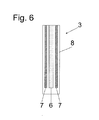
- Fig. 6 a section through a schematic probe unit
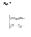
- Fig. 7 in each case a signal curve for the test signals applied to the probe unit.
- Fig. 1 is the basic structure of a capacitive measurement of the level of a medium 4, which is, for example, a liquid or a bulk material, shown in a container 5.
- an electronics unit 1 is provided, which acts here via a cable 2, the probe unit 3 with the drive signal or for the monitoring with the test signal or connects or floats with the appropriate potentials. This is preferably in each case an electrical alternating voltage.
- the electronics unit 1 the contact with ground or floats let controlled for monitoring.
- the probe unit 3 and the wall of the container 5 form a capacitor in conjunction with the medium 4 as a dielectric.
- a second probe unit is preferably provided. If a measuring signal is picked up by the electronic unit 1 from the probe unit 3, the capacitance of the capacitor formed by the probe unit 3, the container 5 and the medium 4 can be determined therefrom.
- the capacity is dependent on which level the medium 4 in the container 5 has. Thus, the determination or monitoring of the capacity allows the determination or monitoring of the level.
- Fig. 2 is the sectional view of the basic structure of a probe unit 3 shown.
- an additional electrode 7 is arranged to the probe electrode 6 coaxially.
- An insulation 8 is located between the additional electrode 7 and the probe electrode 6.
- a similar insulation 8 is also located outside the additional electrode 7.
- the additional electrode 7 is only partially insulated. In a further embodiment, it is a completely bare, or in an additional embodiment, a completely insulated additional electrode 7.
- the additional electrode 7 which can also be referred to here as a guard electrode, no additional capacitive effect, so that between the probe electrode 6 and the container wall or the second electrode directly the measuring capacitance Cmess can be measured. This then also the determination or monitoring of the level is possible.
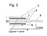
- Fig. 3 is another case of the application of the electrodes 6, 7 shown.
- the basic structure of the probe unit 3 differs from that in Fig. 2 not shown.
- the probe electrode 6 is acted upon by an alternating voltage signal as a test signal, wherein the additional electrode 7 is grounded.
- the guard of the probe unit is where is about the additional electrode 7, so to speak inactive and the measured capacitance is composed of the actual capacitance C measurement, which is a function of the medium, and the constant capacitance Cguard between the probe electrode 6 and additional electrode. 7
- the probe electrode 6 is given the excitation signal as a test signal and the auxiliary electrode 7 is left floating, i. she is not charged with a potential. This allows a normal measurement of the level at which the additional electrode 7 plays virtually no role.
- the excitation signal is given as a test signal and the auxiliary electrode 7 is connected to ground (shown in the Fig. 3 ).
- a capacitance value results which depends on the medium and an offset. This offset can be adjusted for example during production or during startup. In particular, it should be constant, so that a change is due to a deterioration of the probe unit.
- the excitation signal is given as a test signal and the additional electrode 7 is beat with a Guardsignal, ie on both electrodes 6, 7 is given the amplitude and in phase AC signal (shown in the Fig. 2 ). In this case results in functionally reliable probe unit 3 only the medium-dependent capacity.
- the probe electrode 6 is left floating and the excitation signal is applied to the auxiliary electrode 7 as a test signal.
- the additional electrode 7 acts as a measuring probe and from the corresponding measured from the additional electrode 7 measurement signal is determined as in a normal measurement of the level of the medium. This case thus corresponds to the above case 1.
- the probe electrode 6 is connected to ground, the Excitation signal is given as a test signal to the additional electrode 7.
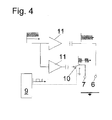
- FIG. 4 is a schematic diagram shown.
- a microprocessor 9 controls a switch 10 with a square wave signal and thus clocks the signal which is applied to the additional electrode 7.
- the probe electrode 6 is also acted upon by an amplifier 11 with the drive signal.
- the reference is given in each case mass, wherein the mass is given either by the additional electrode or by the wall of the container.
- a capacitor behind the amplifier 11 filters out the DC voltage component from the signals.
- a further embodiment of the probe unit 3 is shown, in which a ground electrode 12, the auxiliary electrode 7 and the probe electrode 6 coaxially.
- it is a proximity switch, in particular, the electrodes 6, 7, 12 ends flat.
- the probe unit 3 is substantially tubular, wherein the process or the medium-facing end of the probe unit 3 allows both access to the probe electrode 6, as well as on the additional electrode 7. Between the probe electrode 6 and the additional electrode 7 and the additional electrode 7 and the ground electrode 12 there is an insulation 8.
- a probe unit 3 is shown, which is rod-shaped.
- An alternative to this is a rope-shaped design.
- the probe electrode 6 is coaxially surrounded by the additional electrode 7 to its end.
- the design is rotationally symmetrical, so that the additional electrode 7 tubular is designed.
- An insulation 8 is also located between the probe electrode 6 and the additional electrode 7 or completely around the additional electrode 7.
- the insulation 8 also fulfills the goal of aggressive media, so that the probe unit 3 is thus protected from damage.
- the insulation also prevents, however, that a direct electrical connection between the probe unit 3 and the wall of the container 5 and the second electrode occurs.
- the additional electrode 7 is completely isolated here.
- the Fig. 7 shows the different signals with which, for example, in one embodiment, the probe electrode 6 and the additional electrode 7 are applied as test signals.
- a normal sinusoidal signal passes, wherein on the additional electrode 7 in the case shown here first an in phase, then a ground potential and then a phase-shifted by 180 ° electrical AC voltage signal is given.
- a test signal is applied to the probe electrode 6 and another test signal to the auxiliary electrode.
- a response signal from the probe electrode 6 is then tapped. This response signal is then evaluated in conjunction with a second response signal with respect to the state of the meter.
- Table 2 1 electronics unit 2 electric wire 3 probe unit 4 medium 5 container 6 probe electrode 7 additional electrode 8th isolation 9 microprocessor 10 switch 11 amplifier 12 ground electrode
Landscapes
- Physics & Mathematics (AREA)
- Fluid Mechanics (AREA)
- General Physics & Mathematics (AREA)
- Engineering & Computer Science (AREA)
- Power Engineering (AREA)
- Electromagnetism (AREA)
- Thermal Sciences (AREA)
- Measurement Of Levels Of Liquids Or Fluent Solid Materials (AREA)
- Measurement Of Resistance Or Impedance (AREA)
- Testing Of Short-Circuits, Discontinuities, Leakage, Or Incorrect Line Connections (AREA)
- Measuring Leads Or Probes (AREA)
- Investigating Or Analyzing Materials By The Use Of Electric Means (AREA)
Applications Claiming Priority (1)
| Application Number | Priority Date | Filing Date | Title |
|---|---|---|---|
| DE102007003887A DE102007003887A1 (de) | 2007-01-19 | 2007-01-19 | Verfahren zur Bedienung einer Vorrichtung zur kapazitiven Bestimmung und/oder Überwachung einer Prozessgröße |
Publications (3)
| Publication Number | Publication Date |
|---|---|
| EP1947429A2 true EP1947429A2 (fr) | 2008-07-23 |
| EP1947429A3 EP1947429A3 (fr) | 2011-01-26 |
| EP1947429B1 EP1947429B1 (fr) | 2013-04-03 |
Family
ID=39356617
Family Applications (1)
| Application Number | Title | Priority Date | Filing Date |
|---|---|---|---|
| EP07123857A Active EP1947429B1 (fr) | 2007-01-19 | 2007-12-20 | Procédé destiné à la commande d'un dispositif de détermination capacitive et/ou de surveillance d'une grandeur de processus |
Country Status (3)
| Country | Link |
|---|---|
| US (1) | US8044671B2 (fr) |
| EP (1) | EP1947429B1 (fr) |
| DE (1) | DE102007003887A1 (fr) |
Cited By (1)
| Publication number | Priority date | Publication date | Assignee | Title |
|---|---|---|---|---|
| DE102011007908A1 (de) | 2011-04-21 | 2012-10-25 | Endress+Hauser Meßtechnik GmbH+Co.KG | Verfahren und Vorrichtung zur Leckageerkennung von Molchen in Molchanlagen |
Families Citing this family (6)
| Publication number | Priority date | Publication date | Assignee | Title |
|---|---|---|---|---|
| DE102008035635B4 (de) * | 2008-07-31 | 2020-11-05 | Gerd Reime | Vorrichtung zur kapazitiven Messung eines Füllstands oder eines Pegels eines Mediums |
| DE102008043412A1 (de) | 2008-11-03 | 2010-05-06 | Endress + Hauser Gmbh + Co. Kg | Vorrichtung zur Bestimmung und/oder Überwachung einer Prozessgröße eines Mediums |
| DE102012022927A1 (de) * | 2012-11-24 | 2014-05-28 | Brose Fahrzeugteile Gmbh & Co. Kommanditgesellschaft, Hallstadt | Kapazitiver Näherungssensor |
| DE102013102055A1 (de) * | 2013-03-01 | 2014-09-18 | Endress + Hauser Gmbh + Co. Kg | Verfahren und Vorrichtung zur Überwachung eines vorgegebenen Füllstands eines Mediums in einem Behälter |
| DE102015004476A1 (de) * | 2015-04-07 | 2016-10-13 | Lucas Automotive Gmbh | Steuerungs-System und Verfahren zum Unterstützen eines sicheren Einscherens von Kraftfahrzeugen nach einem Überholvorgang |
| EP3457096B1 (fr) * | 2017-09-13 | 2021-07-07 | Intersens | Sonde améliorée pour dispositif limiteur de remplissage pour citerne de transport de carburant pétrolier et dispositif limiteur de remplissage correspondant |
Citations (2)
| Publication number | Priority date | Publication date | Assignee | Title |
|---|---|---|---|---|
| DE3212434C2 (de) | 1982-04-02 | 1984-06-14 | Endress U. Hauser Gmbh U. Co, 7867 Maulburg | Fuellstandsgrenzschalter fuer elektrisch leitende fuellgueter |
| DE102004050495A1 (de) | 2004-10-15 | 2006-04-27 | Endress + Hauser Gmbh + Co. Kg | Vorrichtung zur kapazitiven Füllstandsmessung |
Family Cites Families (12)
| Publication number | Priority date | Publication date | Assignee | Title |
|---|---|---|---|---|
| GB8602742D0 (en) * | 1986-02-04 | 1986-03-12 | Mestra Ag | Capacitive sensor circuit |
| US4806847A (en) * | 1986-12-09 | 1989-02-21 | Caterpillar Inc. | Dielectric liquid level sensor and method |
| US4831325A (en) * | 1987-04-01 | 1989-05-16 | General Signal Corporation | Capacitance measuring circuit |
| US5396803A (en) * | 1993-07-07 | 1995-03-14 | Tylan General, Inc. | Dual balanced capacitance manometers for suppressing vibration effects |
| DE19502195A1 (de) * | 1995-01-25 | 1996-08-01 | Grieshaber Vega Kg | Verfahren und Anordnung zur Auswertung der Signale eines kapazitiven Füllstandsensors |
| US6476620B2 (en) * | 1996-09-06 | 2002-11-05 | Ks Techno Co., Ltd. | Electrostatic capacity sensor |
| FR2780499B1 (fr) * | 1998-06-25 | 2000-08-18 | Schlumberger Services Petrol | Dispositifs de caracterisation de l'ecoulement d'un fluide polyphasique |
| DE19836770C1 (de) * | 1998-08-13 | 2000-04-20 | Siemens Ag | Verfahren zur kapazitiven Bilderfassung |
| DE19916979A1 (de) * | 1999-04-15 | 2000-11-02 | Sican Gmbh | Verfahren zur Füllstandsmessung und Füllstandssensor |
| JP4531469B2 (ja) * | 2004-07-15 | 2010-08-25 | 株式会社フジクラ | 静電容量式近接センサ |
| US7288945B2 (en) * | 2004-08-18 | 2007-10-30 | Southwest Research Institute | Systems and methods for detection of dielectric change in material and structure |
| US8050876B2 (en) * | 2005-07-18 | 2011-11-01 | Analog Devices, Inc. | Automatic environmental compensation of capacitance based proximity sensors |
-
2007
- 2007-01-19 DE DE102007003887A patent/DE102007003887A1/de not_active Withdrawn
- 2007-12-20 EP EP07123857A patent/EP1947429B1/fr active Active
-
2008
- 2008-01-18 US US12/010,011 patent/US8044671B2/en not_active Expired - Fee Related
Patent Citations (2)
| Publication number | Priority date | Publication date | Assignee | Title |
|---|---|---|---|---|
| DE3212434C2 (de) | 1982-04-02 | 1984-06-14 | Endress U. Hauser Gmbh U. Co, 7867 Maulburg | Fuellstandsgrenzschalter fuer elektrisch leitende fuellgueter |
| DE102004050495A1 (de) | 2004-10-15 | 2006-04-27 | Endress + Hauser Gmbh + Co. Kg | Vorrichtung zur kapazitiven Füllstandsmessung |
Cited By (1)
| Publication number | Priority date | Publication date | Assignee | Title |
|---|---|---|---|---|
| DE102011007908A1 (de) | 2011-04-21 | 2012-10-25 | Endress+Hauser Meßtechnik GmbH+Co.KG | Verfahren und Vorrichtung zur Leckageerkennung von Molchen in Molchanlagen |
Also Published As
| Publication number | Publication date |
|---|---|
| EP1947429B1 (fr) | 2013-04-03 |
| DE102007003887A1 (de) | 2008-07-24 |
| EP1947429A3 (fr) | 2011-01-26 |
| US8044671B2 (en) | 2011-10-25 |
| US20080297177A1 (en) | 2008-12-04 |
Similar Documents
| Publication | Publication Date | Title |
|---|---|---|
| EP1947429B1 (fr) | Procédé destiné à la commande d'un dispositif de détermination capacitive et/ou de surveillance d'une grandeur de processus | |
| EP2400275B1 (fr) | Mesure du niveau de remplissage de liquides sans contact | |
| EP3152530B1 (fr) | Procédé et dispositif de surveillance du niveau d'un milieu dans un récipient | |
| WO2012100873A1 (fr) | Dispositif et procédé pour la mesure capacitive d'un niveau de remplissage | |
| EP3390981B1 (fr) | Adaptateur de capteur | |
| DE2755517A1 (de) | Kapazitive vorrichtung zur messung eines fluessigkeitspegels | |
| WO2011080018A1 (fr) | Dispositif servant à détecter un niveau | |
| DE102010030362A1 (de) | Vorrichtung und Verfahren zur kapazitiven Bestimmung eines Füllstandes einer Flüssigkeit in einem Behälter | |
| EP3652508A1 (fr) | Procédé de mesure capacitive et dispositif de mesure de niveau | |
| DE4447295A1 (de) | Verfahren und Vorrichtung zur Bestimmung einer jeweiligen örtlichen Position eines Körpers durch kapazitive Abtastung | |
| EP2759812A1 (fr) | Procédé et dispositif de mesure capacitive du niveau de remplissage de liquides ou produits en vrac | |
| EP3449226B1 (fr) | Élément de couplage pour un appareil de mesure de niveau de remplissage capacitif | |
| EP2092279B1 (fr) | Dispositif pour déterminer et/ou surveiller une grandeur de traitement | |
| DE10256064A1 (de) | Verfahren und Vorrichtung zur Bestimmung des Wassergehalts und der Leitfähigkeit in Böden und Schüttgütern | |
| EP4134637B1 (fr) | Sonde capacitive de niveau de remplissage sans zone morte | |
| DE102011078369B4 (de) | Kapazitive Sensoreinrichtung sowie Verfahren zum Kalibrieren einer kapazitiven Sensoreinrichtung | |
| EP2118625A1 (fr) | Dispositif destine a determiner et/ou a surveiller un parametre de traitement | |
| EP0711978A2 (fr) | Procédé et dispositif pour déterminer la position réelle d'un objet par balayage capacitif | |
| EP2735851B1 (fr) | Procédé et dispositif de mesure du niveau de remplissage capacitif avec sonde à câble ou sonde à tige | |
| WO2007048739A1 (fr) | Dispositif de détermination capacitive et/ou de surveillance du niveau de remplissage d’un produit | |
| EP3665447B1 (fr) | Dispositif et procédé de mesure capacitive d'un niveau de remplissage d'un milieu de remplissage | |
| EP3444575B1 (fr) | Dispositif capteur destiné à la mesure potentiometrique d'une hauteur de niveau de remplissage dans un recipient | |
| EP2607932B1 (fr) | Procédé de mesure capacitif avec directivité commandable et capteur capacitif adapté pour l'usage industriel | |
| WO2009135757A1 (fr) | Procédé permettant de déterminer des valeurs de référence pour des valeurs de mesure d’une capacité à mesurer avec un appareil de mesure capacitif | |
| DE202018101917U1 (de) | Schutzvorrichtung für Sondeneinheit eines Feldgeräts |
Legal Events
| Date | Code | Title | Description |
|---|---|---|---|
| PUAI | Public reference made under article 153(3) epc to a published international application that has entered the european phase |
Free format text: ORIGINAL CODE: 0009012 |
|
| AK | Designated contracting states |
Kind code of ref document: A2 Designated state(s): AT BE BG CH CY CZ DE DK EE ES FI FR GB GR HU IE IS IT LI LT LU LV MC MT NL PL PT RO SE SI SK TR |
|
| AX | Request for extension of the european patent |
Extension state: AL BA HR MK RS |
|
| PUAL | Search report despatched |
Free format text: ORIGINAL CODE: 0009013 |
|
| AK | Designated contracting states |
Kind code of ref document: A3 Designated state(s): AT BE BG CH CY CZ DE DK EE ES FI FR GB GR HU IE IS IT LI LT LU LV MC MT NL PL PT RO SE SI SK TR |
|
| AX | Request for extension of the european patent |
Extension state: AL BA HR MK RS |
|
| 17P | Request for examination filed |
Effective date: 20110627 |
|
| AKX | Designation fees paid |
Designated state(s): AT BE BG CH CY CZ DE DK EE ES FI FR GB GR HU IE IS IT LI LT LU LV MC MT NL PL PT RO SE SI SK TR |
|
| GRAP | Despatch of communication of intention to grant a patent |
Free format text: ORIGINAL CODE: EPIDOSNIGR1 |
|
| GRAS | Grant fee paid |
Free format text: ORIGINAL CODE: EPIDOSNIGR3 |
|
| GRAA | (expected) grant |
Free format text: ORIGINAL CODE: 0009210 |
|
| AK | Designated contracting states |
Kind code of ref document: B1 Designated state(s): AT BE BG CH CY CZ DE DK EE ES FI FR GB GR HU IE IS IT LI LT LU LV MC MT NL PL PT RO SE SI SK TR |
|
| REG | Reference to a national code |
Ref country code: GB Ref legal event code: FG4D Free format text: NOT ENGLISH |
|
| REG | Reference to a national code |
Ref country code: CH Ref legal event code: EP Ref country code: AT Ref legal event code: REF Ref document number: 605009 Country of ref document: AT Kind code of ref document: T Effective date: 20130415 |
|
| REG | Reference to a national code |
Ref country code: IE Ref legal event code: FG4D Free format text: LANGUAGE OF EP DOCUMENT: GERMAN |
|
| REG | Reference to a national code |
Ref country code: DE Ref legal event code: R096 Ref document number: 502007011540 Country of ref document: DE Effective date: 20130529 |
|
| PG25 | Lapsed in a contracting state [announced via postgrant information from national office to epo] |
Ref country code: SI Free format text: LAPSE BECAUSE OF FAILURE TO SUBMIT A TRANSLATION OF THE DESCRIPTION OR TO PAY THE FEE WITHIN THE PRESCRIBED TIME-LIMIT Effective date: 20130403 |
|
| REG | Reference to a national code |
Ref country code: NL Ref legal event code: VDEP Effective date: 20130403 |
|
| REG | Reference to a national code |
Ref country code: LT Ref legal event code: MG4D |
|
| PG25 | Lapsed in a contracting state [announced via postgrant information from national office to epo] |
Ref country code: GR Free format text: LAPSE BECAUSE OF FAILURE TO SUBMIT A TRANSLATION OF THE DESCRIPTION OR TO PAY THE FEE WITHIN THE PRESCRIBED TIME-LIMIT Effective date: 20130704 Ref country code: FI Free format text: LAPSE BECAUSE OF FAILURE TO SUBMIT A TRANSLATION OF THE DESCRIPTION OR TO PAY THE FEE WITHIN THE PRESCRIBED TIME-LIMIT Effective date: 20130403 Ref country code: NL Free format text: LAPSE BECAUSE OF FAILURE TO SUBMIT A TRANSLATION OF THE DESCRIPTION OR TO PAY THE FEE WITHIN THE PRESCRIBED TIME-LIMIT Effective date: 20130403 Ref country code: SE Free format text: LAPSE BECAUSE OF FAILURE TO SUBMIT A TRANSLATION OF THE DESCRIPTION OR TO PAY THE FEE WITHIN THE PRESCRIBED TIME-LIMIT Effective date: 20130403 Ref country code: LT Free format text: LAPSE BECAUSE OF FAILURE TO SUBMIT A TRANSLATION OF THE DESCRIPTION OR TO PAY THE FEE WITHIN THE PRESCRIBED TIME-LIMIT Effective date: 20130403 Ref country code: IS Free format text: LAPSE BECAUSE OF FAILURE TO SUBMIT A TRANSLATION OF THE DESCRIPTION OR TO PAY THE FEE WITHIN THE PRESCRIBED TIME-LIMIT Effective date: 20130803 Ref country code: ES Free format text: LAPSE BECAUSE OF FAILURE TO SUBMIT A TRANSLATION OF THE DESCRIPTION OR TO PAY THE FEE WITHIN THE PRESCRIBED TIME-LIMIT Effective date: 20130714 Ref country code: PT Free format text: LAPSE BECAUSE OF FAILURE TO SUBMIT A TRANSLATION OF THE DESCRIPTION OR TO PAY THE FEE WITHIN THE PRESCRIBED TIME-LIMIT Effective date: 20130805 |
|
| PG25 | Lapsed in a contracting state [announced via postgrant information from national office to epo] |
Ref country code: CY Free format text: LAPSE BECAUSE OF FAILURE TO SUBMIT A TRANSLATION OF THE DESCRIPTION OR TO PAY THE FEE WITHIN THE PRESCRIBED TIME-LIMIT Effective date: 20130403 Ref country code: BG Free format text: LAPSE BECAUSE OF FAILURE TO SUBMIT A TRANSLATION OF THE DESCRIPTION OR TO PAY THE FEE WITHIN THE PRESCRIBED TIME-LIMIT Effective date: 20130703 Ref country code: LV Free format text: LAPSE BECAUSE OF FAILURE TO SUBMIT A TRANSLATION OF THE DESCRIPTION OR TO PAY THE FEE WITHIN THE PRESCRIBED TIME-LIMIT Effective date: 20130403 Ref country code: PL Free format text: LAPSE BECAUSE OF FAILURE TO SUBMIT A TRANSLATION OF THE DESCRIPTION OR TO PAY THE FEE WITHIN THE PRESCRIBED TIME-LIMIT Effective date: 20130403 |
|
| PG25 | Lapsed in a contracting state [announced via postgrant information from national office to epo] |
Ref country code: CZ Free format text: LAPSE BECAUSE OF FAILURE TO SUBMIT A TRANSLATION OF THE DESCRIPTION OR TO PAY THE FEE WITHIN THE PRESCRIBED TIME-LIMIT Effective date: 20130403 Ref country code: DK Free format text: LAPSE BECAUSE OF FAILURE TO SUBMIT A TRANSLATION OF THE DESCRIPTION OR TO PAY THE FEE WITHIN THE PRESCRIBED TIME-LIMIT Effective date: 20130403 Ref country code: SK Free format text: LAPSE BECAUSE OF FAILURE TO SUBMIT A TRANSLATION OF THE DESCRIPTION OR TO PAY THE FEE WITHIN THE PRESCRIBED TIME-LIMIT Effective date: 20130403 Ref country code: EE Free format text: LAPSE BECAUSE OF FAILURE TO SUBMIT A TRANSLATION OF THE DESCRIPTION OR TO PAY THE FEE WITHIN THE PRESCRIBED TIME-LIMIT Effective date: 20130403 |
|
| PLBE | No opposition filed within time limit |
Free format text: ORIGINAL CODE: 0009261 |
|
| STAA | Information on the status of an ep patent application or granted ep patent |
Free format text: STATUS: NO OPPOSITION FILED WITHIN TIME LIMIT |
|
| PG25 | Lapsed in a contracting state [announced via postgrant information from national office to epo] |
Ref country code: RO Free format text: LAPSE BECAUSE OF FAILURE TO SUBMIT A TRANSLATION OF THE DESCRIPTION OR TO PAY THE FEE WITHIN THE PRESCRIBED TIME-LIMIT Effective date: 20130403 |
|
| 26N | No opposition filed |
Effective date: 20140106 |
|
| REG | Reference to a national code |
Ref country code: DE Ref legal event code: R097 Ref document number: 502007011540 Country of ref document: DE Effective date: 20140106 |
|
| BERE | Be: lapsed |
Owner name: ENDRESS+HAUSER GMBH+CO. K.G. Effective date: 20131231 |
|
| REG | Reference to a national code |
Ref country code: CH Ref legal event code: PL |
|
| PG25 | Lapsed in a contracting state [announced via postgrant information from national office to epo] |
Ref country code: LU Free format text: LAPSE BECAUSE OF FAILURE TO SUBMIT A TRANSLATION OF THE DESCRIPTION OR TO PAY THE FEE WITHIN THE PRESCRIBED TIME-LIMIT Effective date: 20131220 Ref country code: MC Free format text: LAPSE BECAUSE OF FAILURE TO SUBMIT A TRANSLATION OF THE DESCRIPTION OR TO PAY THE FEE WITHIN THE PRESCRIBED TIME-LIMIT Effective date: 20130403 |
|
| REG | Reference to a national code |
Ref country code: IE Ref legal event code: MM4A |
|
| PG25 | Lapsed in a contracting state [announced via postgrant information from national office to epo] |
Ref country code: LI Free format text: LAPSE BECAUSE OF NON-PAYMENT OF DUE FEES Effective date: 20131231 Ref country code: IE Free format text: LAPSE BECAUSE OF NON-PAYMENT OF DUE FEES Effective date: 20131220 Ref country code: CH Free format text: LAPSE BECAUSE OF NON-PAYMENT OF DUE FEES Effective date: 20131231 Ref country code: BE Free format text: LAPSE BECAUSE OF NON-PAYMENT OF DUE FEES Effective date: 20131231 |
|
| REG | Reference to a national code |
Ref country code: AT Ref legal event code: MM01 Ref document number: 605009 Country of ref document: AT Kind code of ref document: T Effective date: 20131220 |
|
| PG25 | Lapsed in a contracting state [announced via postgrant information from national office to epo] |
Ref country code: AT Free format text: LAPSE BECAUSE OF NON-PAYMENT OF DUE FEES Effective date: 20131220 |
|
| PG25 | Lapsed in a contracting state [announced via postgrant information from national office to epo] |
Ref country code: TR Free format text: LAPSE BECAUSE OF FAILURE TO SUBMIT A TRANSLATION OF THE DESCRIPTION OR TO PAY THE FEE WITHIN THE PRESCRIBED TIME-LIMIT Effective date: 20130403 |
|
| PG25 | Lapsed in a contracting state [announced via postgrant information from national office to epo] |
Ref country code: HU Free format text: LAPSE BECAUSE OF FAILURE TO SUBMIT A TRANSLATION OF THE DESCRIPTION OR TO PAY THE FEE WITHIN THE PRESCRIBED TIME-LIMIT; INVALID AB INITIO Effective date: 20071220 |
|
| PG25 | Lapsed in a contracting state [announced via postgrant information from national office to epo] |
Ref country code: MT Free format text: LAPSE BECAUSE OF FAILURE TO SUBMIT A TRANSLATION OF THE DESCRIPTION OR TO PAY THE FEE WITHIN THE PRESCRIBED TIME-LIMIT Effective date: 20130403 |
|
| REG | Reference to a national code |
Ref country code: FR Ref legal event code: PLFP Year of fee payment: 9 |
|
| REG | Reference to a national code |
Ref country code: FR Ref legal event code: PLFP Year of fee payment: 10 |
|
| REG | Reference to a national code |
Ref country code: FR Ref legal event code: PLFP Year of fee payment: 11 |
|
| REG | Reference to a national code |
Ref country code: DE Ref legal event code: R081 Ref document number: 502007011540 Country of ref document: DE Owner name: ENDRESS+HAUSER SE+CO. KG, DE Free format text: FORMER OWNER: ENDRESS + HAUSER GMBH + CO. KG, 79689 MAULBURG, DE |
|
| PGFP | Annual fee paid to national office [announced via postgrant information from national office to epo] |
Ref country code: GB Payment date: 20201223 Year of fee payment: 14 |
|
| PGFP | Annual fee paid to national office [announced via postgrant information from national office to epo] |
Ref country code: IT Payment date: 20201224 Year of fee payment: 14 |
|
| PGFP | Annual fee paid to national office [announced via postgrant information from national office to epo] |
Ref country code: FR Payment date: 20211224 Year of fee payment: 15 |
|
| GBPC | Gb: european patent ceased through non-payment of renewal fee |
Effective date: 20211220 |
|
| PG25 | Lapsed in a contracting state [announced via postgrant information from national office to epo] |
Ref country code: GB Free format text: LAPSE BECAUSE OF NON-PAYMENT OF DUE FEES Effective date: 20211220 |
|
| PG25 | Lapsed in a contracting state [announced via postgrant information from national office to epo] |
Ref country code: IT Free format text: LAPSE BECAUSE OF NON-PAYMENT OF DUE FEES Effective date: 20211220 |
|
| P01 | Opt-out of the competence of the unified patent court (upc) registered |
Effective date: 20230601 |
|
| PG25 | Lapsed in a contracting state [announced via postgrant information from national office to epo] |
Ref country code: FR Free format text: LAPSE BECAUSE OF NON-PAYMENT OF DUE FEES Effective date: 20221231 |
|
| PGFP | Annual fee paid to national office [announced via postgrant information from national office to epo] |
Ref country code: DE Payment date: 20241210 Year of fee payment: 18 |