EP1947497A2 - Objectif compact très grand angle de type fisheye - Google Patents
Objectif compact très grand angle de type fisheye Download PDFInfo
- Publication number
- EP1947497A2 EP1947497A2 EP08000368A EP08000368A EP1947497A2 EP 1947497 A2 EP1947497 A2 EP 1947497A2 EP 08000368 A EP08000368 A EP 08000368A EP 08000368 A EP08000368 A EP 08000368A EP 1947497 A2 EP1947497 A2 EP 1947497A2
- Authority
- EP
- European Patent Office
- Prior art keywords
- lens
- imaging
- imaging lens
- focal length
- conditional expression
- Prior art date
- Legal status (The legal status is an assumption and is not a legal conclusion. Google has not performed a legal analysis and makes no representation as to the accuracy of the status listed.)
- Granted
Links
- 238000003384 imaging method Methods 0.000 claims abstract description 185
- 230000005499 meniscus Effects 0.000 claims abstract description 7
- 230000014509 gene expression Effects 0.000 claims description 65
- 230000003287 optical effect Effects 0.000 claims description 36
- 239000002131 composite material Substances 0.000 claims description 23
- 230000004075 alteration Effects 0.000 description 39
- 239000000463 material Substances 0.000 description 31
- 238000010586 diagram Methods 0.000 description 25
- 230000004907 flux Effects 0.000 description 6
- 239000011521 glass Substances 0.000 description 6
- 238000009877 rendering Methods 0.000 description 3
- 239000000919 ceramic Substances 0.000 description 2
- 239000006059 cover glass Substances 0.000 description 2
- 238000005336 cracking Methods 0.000 description 2
- 239000000428 dust Substances 0.000 description 2
- 238000012986 modification Methods 0.000 description 2
- 230000004048 modification Effects 0.000 description 2
- 239000000126 substance Substances 0.000 description 2
- 241001417524 Pomacanthidae Species 0.000 description 1
- 239000002253 acid Substances 0.000 description 1
- 201000009310 astigmatism Diseases 0.000 description 1
- 230000000295 complement effect Effects 0.000 description 1
- 239000012141 concentrate Substances 0.000 description 1
- 239000000470 constituent Substances 0.000 description 1
- 239000003599 detergent Substances 0.000 description 1
- 230000006866 deterioration Effects 0.000 description 1
- 230000001747 exhibiting effect Effects 0.000 description 1
- 238000004519 manufacturing process Methods 0.000 description 1
- 229910044991 metal oxide Inorganic materials 0.000 description 1
- 150000004706 metal oxides Chemical class 0.000 description 1
- 235000014593 oils and fats Nutrition 0.000 description 1
- 239000004065 semiconductor Substances 0.000 description 1
- 239000003981 vehicle Substances 0.000 description 1
- 230000003245 working effect Effects 0.000 description 1
Images


Classifications
-
- G—PHYSICS
- G02—OPTICS
- G02B—OPTICAL ELEMENTS, SYSTEMS OR APPARATUS
- G02B13/00—Optical objectives specially designed for the purposes specified below
- G02B13/06—Panoramic objectives; So-called "sky lenses" including panoramic objectives having reflecting surfaces
Definitions
- the present invention relates to an imaging lens and an imaging device equipped with the imaging lens, and more particularly to a wide angle imaging lens suitable for use in an onboard camera, a camera for a portable terminal, a surveillance camera, and the like, using an imaging element, such as a CCD (Charge-Coupled Device), CMOS (Complementary Metal Oxide Semiconductor), or the like, as well as to an imaging device equipped with the imaging lens.
- an imaging element such as a CCD (Charge-Coupled Device), CMOS (Complementary Metal Oxide Semiconductor), or the like, as well as to an imaging device equipped with the imaging lens.
- Imaging lenses described in US Patent No. 7,023,628 , Japanese Patent No.2599312 and JP-A-61-123810 been known as the imaging lens of the foregoing field.
- US Patent No. 7,023,628 describes a fisheye lens consisting of five-grouped six lenses.
- Japanese Patent No.2599312 describes a wide-angle lens which includes five-grouped six lenses or five-grouped seven lenses and which includes an aspheric lens.
- JP-A-61-123810 describes a wide-angle lens which is used for a compact camera of a surveillance camera and which consists of five-grouped six lenses or five-grouped seven lenses.
- US Patent No. 7,023,628 describes a bright lens having an F number of 2, but the lens frequently uses a glass material whose refractive index exceeds a value of 1.9 and hence has a drawback of high cost.
- the lens described in Japanese Patent No.2599312 uses an aspherical lens. When the lens is formed by using glass as a material, the lens also becomes expensive unfavorably. In addition to being insufficiently wide-angle and miniaturized, the lens described in JP-A-61-123810 forms a dark optical system having an F number of 2.8 to 4.
- An object of an illustrative, non-limiting embodiment of the invention is to provide an imaging lens which is compact, wide-angle, bright, and inexpensive and which also maintains superior optical performance, as well as providing an imaging device equipped with the imaging lens.
- an imaging lens including: in order from an object side of the imaging lens, a first lens having a negative refractive power and having a concave surface directed toward an image side of the imaging lens; a second lens that is one of a planoconcave lens having a flat surface directed toward the object side and a biconcave lens whose surface having a larger absolute value of radius of curvature is directed toward the object side; a third biconvex lens; a stop; a fourth lens whose surface having a smaller absolute value of radius of curvature is directed toward the image side, the fourth lens having a positive refractive power; and a cemented lens having a positive refractive power, the cemented lens including a fifth lens and a sixth lens, the fifth lens having a positive refractive power and having a biconvex shape, the sixth lens having a negative refractive power and having a meniscus shape.
- the first imaging lens has a simple configuration including five-grouped six lenses, but an attempt is made to achieve a reduction in size and a wider angle by means of the negative first lens and the negative second lens having the foregoing shapes.
- Various aberrations are well corrected by appropriately selecting the configuration of the positive third lens and the positive fourth lens which are to be arranged in the vicinity of the stop.
- Balanced chromatic aberration is achieved by arranging, on the image surface side, the cemented lens consisting of the negative lens and the positive lens.
- an imaging lens including: in order from an object side of the imaging lens, a first lens having a negative refractive power and having a concave surface directed toward an image side of the imaging lens; a second lens that is one of a planoconcave lens having a flat surface directed toward the object side and a biconcave lens whose surface having a larger absolute value of radius of curvature is directed toward the object side; a third biconvex lens; a stop; a fourth lens having a positive refractive power; and a cemented lens having a positive refractive power, the cemented lens including a fifth lens and a sixth lens, one of the fifth lens and the sixth lens having a positive refractive power and the other having a negative refractive power.
- the third lens satisfies conditional expressions (2) and (3) provided below in connection with an Abbe number ⁇ 3 at the d-line of the third lens and a refractive index N 3 at the d-line of the third lens; and the negative lens forming the cemented lens satisfies a conditional expression (4) provided below in connection with an Abbe number ⁇ n at a d-line of the negative lens: 25 ⁇ v 3 ⁇ 35 1.79 ⁇ N 3 ⁇ 1.87 v n ⁇ 25
- the second imaging lens has a simple configuration including five-grouped six lenses, but an attempt is made to achieve a reduction in size and a wider angle by means of the negative first lens and the negative second lens having the foregoing shapes.
- Various aberrations are well corrected by appropriately selecting the configuration of the positive third lens and the positive fourth lens which are to be arranged in the vicinity of the stop.
- Balanced chromatic aberration is achieved by arranging, on the image surface side, the cemented lens consisting of the negative lens and the positive lens; and appropriately selecting a material for the negative lens.
- either the positive lens or the negative lens may also be positioned on the object side without regard to the sequence of arrangement of the positive lens and the negative lens constituting the cemented lens.
- a refractive index N p at the d-line of the positive lens constituting the cemented lens, a refractive index N n at the d-line of the negative lens constituting the cemented lens, an Abbe number ⁇ p at the d-line of the positive lens constituting the cemented lens, and the Abbe number ⁇ n at the d-line of the negative lens constituting the cemented lens may satisfy conditional expressions (5) and (6) provided below: 0.05 ⁇ N n - N p ⁇ 0.45 1.5 ⁇ v p / v n ⁇ 5.5
- a composite focal length f 12 of the first lens and the second lens and the focal length f of the entire system preferably may satisfy a conditional expression (7) provided below 0.5 ⁇ f 12 / f ⁇ 2
- a composite focal length f 123 of the first lens, the second lens, and the third lens may satisfy a conditional expression (8) provided below f 123 ⁇ 0
- a composite focal length f 56 of the fifth lens and the sixth lens and the focal length f of the entire system may satisfy a conditional expression (9) provided below 3 ⁇ f 56 / f ⁇ 1
- a distance L, along the optical axis, from the object-side surface of the first lens to an image-side focal plane of the entire system and the focal length f of the entire system may satisfy a conditional expression (10) provided below 7 ⁇ L / f ⁇ 14
- an imaging device including: the above-described imaging lens; and an imaging element for converting an optical image formed by means of the imaging lens into an electric signal.
- an attempt can be made to achieve a reduction in size and a wider angle by means of appropriately selecting shapes of the lenses and a material for the lenses.
- a bright, inexpensive imaging lens and an imaging device equipped with the imaging lens can be provided.
- the imaging lens of the present embodiment can be used for an onboard camera, a camera for a portable terminal, a surveillance camera; and can be suitably used especially for an onboard camera which photographs views in the forward, side, and rear of an automobile, and the like.
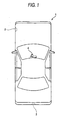
- Fig. 1 shows, as an example use, the imaging lens and the imaging device, both of which pertain to the present embodiment and which are mounted on an automobile 1.
- the automobile 1 has an external camera 2 for imaging a view in the range of a dead angle on the side of a front passenger seat; an external camera 3 for imaging a view in the range of a dead angel on the back side of the automobile 1; and an internal camera 4 mounted on the back of a rearview mirror for imaging the same field of view as that of a driver.
- the external camera 2, the external camera 3, and the internal camera 4 are imaging devices and each have an imaging lens 5 and an imaging element 6 for converting an optical image formed by the imaging lens 5 into an electric signal.
- Fig. 2 shows a cross-sectional view of an optical system which is an example configuration of the imaging lens 5 of the embodiment of the present invention.
- the example configuration shown in Fig. 2 corresponds to a lens configuration of a first example to be described later.
- the imaging lens 5 has five-grouped six lenses, in which a first lens L1, a second lens L2, a third lens L3, an aperture diaphragm St, a fourth lens L4, and a cemented lens L56 including a fifth lens L5 and a sixth lens L6 are arranged, in order from an object side along an optical axis Z.
- various flat optical members PP for example, cover glass for protecting an imaging plane, an infrared cut-off filter, and the like, are interposed between the imaging lens 5 and the imaging element 6.
- a light flux passing outside an effective aperture located between the first lens L 1 and the second L2 reaches the imaging plane as stray light, which may cause a ghost image.
- a light flux 7 shown in Fig. 1 is one which enters at the maximum angle of view. Since a light flux passing through the aperture further outside the location where the light flux 7 passes may turn into stray light, placing shielding means 11 between the first lens L1 and the second lens L2 to block stray light is desirable.
- An area of a surface of the first lens L1, facing the second lens L2, which is outside the effective aperture may be coated with opaque pain or provided with an opaque plate material as the shielding means 11.
- an opaque plate material may also be placed in an optical path between the first lens L1 and the second lens L2 for the light flux which may turn into stray light.
- the shielding means intended for this purpose may also be placed between other lenses, as required.
- Fig. 2 shows an example where shielding means 12 having the same configuration as that of the shielding means 11 is provided on an area of a surface of the second lens L2, facing the third lens L3, which is outside the effective aperture.
- the first lens L1 is a negative lens whose concave surface is directed toward an image side.
- the configuration enables narrowing of a light flux having exited the first lens L1 and miniaturization of the imaging lens.
- the first lens L1 is embodied as a negative lens of meniscus shape whose convex surface is directed toward an object side as in the case of an embodiment shown in Fig. 2 , a light ray of large incident angle can be captured on the object-side convex surface of the first lens L1, and hence the angle of the optical system can be made wider.
- a Petzval sum can be reduced, so that a field curvature can be corrected over a wide screen area.
- the first lens L1 is provided most closely to the object side, when the imaging lens is used in a severe environment as in the case of; for example, an onboard camera, a material which is resistant to surface deterioration caused by weather and temperature changes caused by direct sunlight and which is also resistant to chemicals such as oils and fats and a detergent; namely, a material exhibiting high waterproof, weather resistance, acid resistance, chemical resistance, and the like, can be used.
- a hard material resistant to cracking as a material of the first lens L1 is preferable.
- glass or ceramics can be used. Ceramics are higher in strength than ordinary glass and posses high heat resistance.
- the second lens L2 is a planoconcave lens whose flat surface is directed toward the object side or a biconcave lens whose surface having a larger absolute value of radius of curvature is directed toward the object side.
- the imaging lens of the present embodiment is used in an environment where the lens is susceptible to repeated vibration or physical impact, as in the case of; for example, an onboard camera
- dust may be generated as a result of chipping of contacted areas when both lenses are brought into edge contact with each other.
- a conceivable countermeasure is to insert a mechanical component between the first lens and the second lens, to thus avoid occurrence of edge contact, which will be a factor for an increase in cost.
- the third lens L3 is of biconvex shape, and a material is selected in such a manner that an Abbe number ⁇ 3 at d-line of the lens satisfies a relationship of v 3 ⁇ 43
- the third lens L3 is disposed in the vicinity of the location of the aperture diaphragm on which light rays densely concentrate, and acts on diverging rays exiting from the first lens L1 and the second lens L2, which are negative lenses, in a direction to cause the rays to converge.
- a curvature of field can be corrected well.
- the third lens L3 When the third lens L3 is formed into a convex lens whose surface having a larger absolute value of radius of curvature is directed toward the object side as in the case of the example shown in Fig. 2 , the field curvature can be corrected in a more superior manner. Moreover, a material for the third lens L3 is selected so as to satisfy the conditional expression (1), lateral chromatic aberration can be corrected well.
- the material can be selected in such a way that the Abbe number ⁇ 3 at the d-line of the third lens satisfies a relationship of v 3 ⁇ 37 In this case, the lateral chromatic aberration can be corrected well.
- the material can be selected in such a way that the Abbe number ⁇ 3 at the d-line of the third lens and a refractive index N 3 at the d-line satisfy a relationship of 25 ⁇ v 3 ⁇ 35 1.79 ⁇ N 3 ⁇ 1.87
- the third lens L3 may further satisfy the conditional expression (3).
- the conditional expression (3) when the lower limit of the conditional expression (3) is crossed, a field curvature becomes unfavorably greater. In contrast, when the upper limit of the conditional expression (3) is crossed, an available material becomes expensive, which unfavorably adds to cost.
- the material can be selected in such a way that the Abbe number ⁇ 3 at the d-line of the third lens and the refractive index N 3 at the d-line satisfy a relationship of 28 ⁇ v 3 ⁇ 35 1.79 ⁇ N 3 ⁇ 1.82 In this case, chromatic aberration and field curvature can be corrected much better.
- the fourth lens L4 has a positive refractive power, and a surface having a smaller absolute value of radius of curvature may be directed toward the image side.
- the fourth lens L4 may be formed into a planoconvex lens or a biconvex lens.
- the cemented lens L56 has entirely a positive refractive power and includes two lenses: one having a positive refractive power and the other having a negative refractive power.
- No limitations are imposed on the sequence of arrangement of the positive lens and the negative lens constituting the cemented lens L56, and either the positive lens or the negative lens may also be positioned on the object side.
- descriptions will be provided hereunder by reference to an example shown in Fig. 2 while a case-where the positive lens corresponds to the fifth lens L5 and where the negative lens corresponds to the six lens L6-is taken as an example.
- the positive fifth lens L5 may be a biconvex shape
- the negative sixth lens L6 may be a meniscus shape.
- a material for the sixth lens L6 that is the negative lens can be selected in such a way that an Abbe number ⁇ n at the d-line of the sixth lens satisfies a relationship of v n ⁇ 25
- a material for the positive lens constituting the cemented lens 56 namely, the fifth lens L5
- the material which is expensive and hard to machine in order to correct chromatic aberration well. Since the material becomes a factor for an increase in cost, crossing of the upper limit of the conditional expression (4) is not preferable.
- the material for the sixth lens L6 can be selected so as to satisfy a relationship of v n ⁇ 20
- a material having a larger Abbe number can be selected for the positive lens constituting the cemented lens L56; namely, the fifth lens L5, when compared with the case of the previously-described conditional expression (4).
- the refractive index Np at the d-line of the positive lens (the fifth lens L5 of the present embodiment) constituting the cemented lens 56, the refractive index N n the d-line of the negative lens (the sixth lens L6 of the present embodiment) constituting the cemented lens L56, an Abbe number ⁇ p at the d-line of the positive lens constituting the cemented lens L56, and the Abbe number ⁇ n at the d-line of the negative lens constituting the cemented lens 56 may satisfy conditional expressions (5) and (6) provided below: 0.05 ⁇ N n - N p ⁇ 0.45 1.5 ⁇ v p / v n ⁇ 5.5
- the cemented lens L56 may satisfy: 1.5 ⁇ v 5 / v 6 ⁇ 4.3
- the lower limit of the conditional expression (6-1) When the lower limit of the conditional expression (6-1) is crossed, difficulty is encountered in well correcting longitudinal chromatic aberration and lateral chromatic aberration.
- the upper limit of the conditional expression (6-1) When the upper limit of the conditional expression (6-1) is crossed, a material for the fifth lens L5 becomes expensive and difficult to machine. By confining the value of the Abbe number to the upper limit of the conditional expression (6-1), cost reduction can be pursued further.
- the cemented lens L56 is constituted by the positive fifth lens L5 and the negative sixth lens L6 and when no limitation is specifically imposed on shapes of these lenses, it is desirable that the following relationship be satisfied: 1.5 ⁇ v 5 / v 6
- a composite focal length f 12 of the first lens and the second lens and the focal length f of the entire system may satisfy a conditional expression (7) provided below: 0.5 ⁇ f 12 / f ⁇ 2
- a conditional expression (7) provided below: 0.5 ⁇ f 12 / f ⁇ 2
- a composite focal length f 123 of the first lens, the second lens, and the third lens may satisfy a conditional expression (8) provided below: f 123 ⁇ 0
- conditional expression (8) provided below: f 123 ⁇ 0
- a composite focal length f 56 of the fifth lens and the sixth lens and the focal length f of the entire system may satisfy a conditional expression (9) provided below: 3 ⁇ f 56 / f ⁇ 10
- a conditional expression (9) provided below: 3 ⁇ f 56 / f ⁇ 10
- a distance L from the object-side surface of the first lens to the image-side focal surface of the first lens along the optical axis Z and the focal length f of the entire system may satisfy: 7 ⁇ L / f ⁇ 14
- the lower limit of the conditional expression (10) is crossed, difficulty is encountered in rendering the lens wider-angle.
- the upper limit of the conditional expression (10) is crossed, the lens becomes bulky.
- a center thickness D1 of the first lens L1 and the focal length f of the entire system may satisfy: 0.55 ⁇ D ⁇ 1 / f
- the first lens L1 is required to have strength against various physical impacts.
- the lower limit of the conditional expression (11) is crossed, the first lens L1 becomes thin, to thus become vulnerable to cracking.
- the strength of the first lens against various physical impacts becomes weak.
- a composite focal length f 456 of the fourth lens L4, the fifth lens L5, and the sixth lens L6 and the focal length f of the entire system may satisfy: 1.7 ⁇ f 456 / f ⁇ 3.0
- an optical member PP such as cover glass, a filter, or the like
- a material for all of the lenses may be glass. Specifically, the material can be used over a wide temperature range from -40°C to 125°C. In order to inexpensively manufacture lenses, all of the lenses can be spherical lenses.
- the shapes and glass materials of the lenses are appropriately selected in relation to the simple configuration consisting of the five-grouped six lenses.
- an attempt can be made to achieve a wider angle and a reduction in size while superior optical performance is ensured, and an inexpensive lens can be embodied.
- there can be implemented compact, inexpensive, superior optical performance while satisfying specifications; namely, a bright F/number of 2.0 and a wide angle of 100° or more for a full angle of view.
- Table 1 shows values of specifications, design specifications, and focal lengths of the imaging lens of the first example.
- Nd7 designates a refractive index of the optical member PP, and vd7 designates an Abbe number of the optical member PP.
- Table 1 the unit of a radius of curvature and on-axis surface spacing is mm. The radius of curvature assumes a positive sign when the object-side surface is convex, as well as assuming a negative sign when the image-side surface is convex.
- L' designates a distance from the object-side surface of the first lens L1 to the image-side focal surface of the same along the optical axis Z when the optical member PP is interposed between the sixth lens L6 and the image surface;
- L designates a distance from the object-side surface of the first lens L1 to the image-side focal surface of the same along the optical axis Z (a distance corresponding to the optical member PP is converted into air);
- "f" designates a focal length of the entire system;
- f 12 designates a composite focal length consisting of the first lens L1 and the second lens L2;
- f 56 designates a composite focal length consisting of the fifth lens L5 and the sixth lens L6;
- f 123 designates a composite focal length of the first lens L1, the second lens L2, and the third lens L3; and
- f 456 designates a composite focal length of the fourth lens L4,
- FIG. 3 The block diagram of the lens of the first embodiment is shown in Fig. 3 .
- An aperture diaphragm St shown in Fig. 3 does not represent the shape and size of the diaphragm but the location of the diaphragm along the optical axis Z.
- Reference symbols in Table 1 and Fig. 3 are provided along with the aperture diaphragm St and the optical member PP.
- an imaging surface 6a of the imaging element 6 is illustrated as an image-formation surface.
- Example 1 Si Ri Di Ndj ⁇ dj L' 20.7 1 15.33 1.95 1.8348 42.7 L 20.6 2 3.76 2.16 FNo. 2.0 3 ⁇ 0.80 1.7725 49.6 2 ⁇ 177.0 4 2.78 1.01 f 1.8 5 17.21 2.69 1.8340 37.2 f 12 -1.9 6 -6.37 1.55 f 56 10.6 7 Aperture Diaphragm ⁇ 0.34 f 123 -9.4 8 ⁇ 3.00 1.7550 52.3 f 456 4.3 9 -5.22 0.24 10 7.10 2.80 1.7130 53.9 11 -2.86 1.31 1.9229 18.9 12 -13.18 2.18 13 ⁇ 0.40 1.5168 64.2 14 ⁇ 0.25 15 Imaging Surface ⁇
- Table 2 shows values of specifications of an imaging lens of a second example
- Fig. 4 shows a block diagram of the lens.
- reference symbols Ri and Di correspond to Ri and Di of Table 2.
- TABLE 2 Example 2
- Table 3 shows values of specifications of an imaging lens of a third example
- Fig. 5 shows a block diagram of the lens.
- reference symbols Ri and Di correspond to Ri and Di of Table 3.
- TABLE 3 Example 3
- Table 4 shows values of specifications of an imaging lens of a fourth example
- Fig. 6 shows a block diagram of the lens.
- reference symbols Ri and Di correspond to Ri and Di of Table 4.
- TABLE 4 Example 4 Si Ri Di Ndj ⁇ dj L' 21.2 1 20.00 1.40 1.5168 64.2 L 21.1 2 5.00 2.52 FNo.
- Table 5 shows values of specifications of an imaging lens of a fifth example
- Fig. 7 shows a block diagram of the lens.
- reference symbols Ri and Di correspond to Ri and Di of Table 5.
- Example 5 Si Ri Di Ndj ⁇ dj L' 20.0 1 18.99 1.55 1.8348 42.7 L 19.9 2 3.51 2.16 FNo.
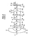
- Table 6 shows values of specifications of an imaging lens of a sixth example
- Fig. 8 shows a block diagram of the lens.
- reference symbols Ri and Di correspond to Ri and Di of Table 6.
- TABLE 6 Example 6
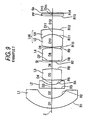
- Table 7 shows values of specifications of an imaging lens of a seventh example
- Fig. 9 shows a block diagram of the lens.
- reference symbols Ri and Di correspond to Ri and Di of Table 7.
- TABLE 7 Example 7 Si Ri Di Ndj ⁇ dj L' 21.2 1 7.73 2.22 2.0820 30.1 L 21.2 2 3.40 2.21 FNo.
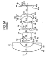
- Table 8 shows values of specifications of an imaging lens of an eighth example, and Fig. 10 shows a block diagram of the lens.
- reference symbols Ri and Di correspond to Ri and Di of Table 8.
- Example 8 Example 6 Si Ri Di Ndj ⁇ dj L' 21.6 1 13.52 2.17 1.8348 42.7 L 21.6 2 3.49 2.18 FNo.
- Table 9 shows values of specifications of an imaging lens of a ninth example, and Fig. 11 shows a block diagram of the lens.
- reference symbols Ri and Di correspond to Ri and Di of Table 9.
- Example 9 Si Ri Di Ndj ⁇ dj L' 20.8 1 20.84 1.66 1.8348 42.7 L 20.7 2 4.77 1.41 FNo.
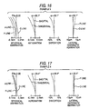
- each of the imaging lenses of the first through ninth example there are arranged the negative first lens L1 whose concave surface is directed toward the image side; the second lens L2 which is a planoconcave lens whose plane surface is directed toward the object side or a biconcave lens whose surface having a larger absolute value of radius of curvature is directed toward the object side; the third lens L3 assuming a biconvex shape; the aperture diaphragm St; the fourth lens L4 whose surface having a smaller absolute value of radius of curvature is directed toward the image side and which has positive refractive power; and the cemented lens L56 consisting of the positive fifth lens L5 assuming a biconvex shape and the meniscus negative sixth lens L6 having positive refractive power.
- the conditional expressions (1) and (3) through (12) are satisfied.
- the conditional expression (2) is also satisfied.
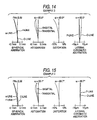
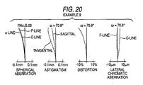
- Figs. 12 through 20 show aberration diagrams of a spherical aberration, astigmatism, distortion, and lateral chromatic aberration of the imaging lenses of the first through ninth examples.
- Each of the aberration diagrams shows an aberration acquired while the e-line (546.07 nm) is taken as a reference wavelength, and the spherical aberration diagram and the lateral chromatic aberration diagram also show aberrations achieved at the F-line (486.1 nm).
- the distortion diagram shows amounts of deviation from f ⁇ (a product of the focal length "f" of the entire system and a half angle of view ⁇ ) which is taken as an ideal height.
- F number of the vertical axis of the spherical aberration diagram shows an F value
- ⁇ of the vertical axes of the other aberration diagrams designate a half angle of view.
- the present invention is not limited to the application and can also be applied to; for example, a camera for a portable terminal, a surveillance camera, and the like.
Landscapes
- Physics & Mathematics (AREA)
- General Physics & Mathematics (AREA)
- Optics & Photonics (AREA)
- Lenses (AREA)
Applications Claiming Priority (1)
| Application Number | Priority Date | Filing Date | Title |
|---|---|---|---|
| JP2007011288A JP4949871B2 (ja) | 2007-01-22 | 2007-01-22 | 撮像レンズ、および該撮像レンズを備えた撮像装置 |
Publications (3)
| Publication Number | Publication Date |
|---|---|
| EP1947497A2 true EP1947497A2 (fr) | 2008-07-23 |
| EP1947497A3 EP1947497A3 (fr) | 2008-08-06 |
| EP1947497B1 EP1947497B1 (fr) | 2012-10-31 |
Family
ID=39186030
Family Applications (1)
| Application Number | Title | Priority Date | Filing Date |
|---|---|---|---|
| EP08000368A Not-in-force EP1947497B1 (fr) | 2007-01-22 | 2008-01-10 | Objectif compact très grand angle de type fisheye |
Country Status (4)
| Country | Link |
|---|---|
| US (1) | US7580205B2 (fr) |
| EP (1) | EP1947497B1 (fr) |
| JP (1) | JP4949871B2 (fr) |
| CN (1) | CN101231379B (fr) |
Cited By (7)
| Publication number | Priority date | Publication date | Assignee | Title |
|---|---|---|---|---|
| TWI485464B (zh) * | 2010-12-30 | 2015-05-21 | Largan Precision Co Ltd | 成像用光學鏡片組 |
| TWI490530B (zh) * | 2013-09-06 | 2015-07-01 | 玉晶光電股份有限公司 | 可攜式電子裝置與其光學成像鏡頭(一) |
| CN109212725A (zh) * | 2018-11-09 | 2019-01-15 | 歌尔股份有限公司 | 一种广角镜头 |
| TWI665486B (zh) * | 2016-04-29 | 2019-07-11 | 大陸商信泰光學(深圳)有限公司 | 廣角鏡頭(十一) |
| CN114217414A (zh) * | 2021-12-20 | 2022-03-22 | 中国科学院长春光学精密机械与物理研究所 | 一种微光物镜光学系统 |
| TWI828879B (zh) * | 2020-03-16 | 2024-01-11 | 揚明光學股份有限公司 | 鏡頭及其製造方法 |
| CN118567069A (zh) * | 2024-05-31 | 2024-08-30 | 福建福光天瞳光学有限公司 | 一种六片式8m前视主摄像头及成像方法 |
Families Citing this family (52)
| Publication number | Priority date | Publication date | Assignee | Title |
|---|---|---|---|---|
| CN101614864B (zh) * | 2009-06-09 | 2010-12-08 | 宁波舜宇车载光学技术有限公司 | 超广角百万像素车载镜头 |
| CN102053342B (zh) * | 2009-10-29 | 2013-05-29 | 比亚迪股份有限公司 | 一种超广角镜头 |
| CN101840057B (zh) * | 2010-05-12 | 2012-01-11 | 秦皇岛视听机械研究所 | 一种用于数字投影机的五组六片式鱼眼镜头基础结构 |
| CN102713718B (zh) | 2010-05-28 | 2013-07-17 | 奥林巴斯医疗株式会社 | 成像光学系统和摄像装置 |
| CN102455488B (zh) * | 2010-10-29 | 2014-07-09 | 鸿富锦精密工业(深圳)有限公司 | 超广角镜头 |
| KR101309423B1 (ko) | 2011-11-22 | 2013-09-23 | 삼성전기주식회사 | 초광각 렌즈 모듈 |
| CN102778745B (zh) * | 2012-08-24 | 2015-01-07 | 江西联创电子股份有限公司 | 高像素鱼眼镜头的透镜成像系统 |
| CN102830484B (zh) * | 2012-10-10 | 2015-11-11 | 金万平 | 一种波段可切换的宽谱段共焦探测光学系统 |
| JP5854966B2 (ja) * | 2012-10-23 | 2016-02-09 | 株式会社タムロン | レンズ系 |
| CN204807792U (zh) * | 2012-12-04 | 2015-11-25 | 富士胶片株式会社 | 广角透镜以及摄像装置 |
| JP6204676B2 (ja) * | 2013-03-29 | 2017-09-27 | キヤノン株式会社 | 撮像レンズ及びそれを有する撮像装置 |
| EP2990847A4 (fr) * | 2013-04-22 | 2016-11-30 | Olympus Corp | Système optique d'objectif grand-angulaire |
| TWI616679B (zh) * | 2013-05-28 | 2018-03-01 | Sony Corp | Camera lens, camera module and camera |
| CN103777320B (zh) | 2013-09-06 | 2016-08-10 | 玉晶光电(厦门)有限公司 | 可携式电子装置与其光学成像镜头 |
| TWI459027B (zh) | 2013-10-31 | 2014-11-01 | 玉晶光電股份有限公司 | 光學成像鏡頭及應用此鏡頭之電子裝置 |
| KR102180476B1 (ko) | 2013-12-17 | 2020-11-18 | 삼성전자주식회사 | 촬상 렌즈 시스템 및 이를 채용한 촬상 장치 |
| KR101547461B1 (ko) * | 2013-12-31 | 2015-08-27 | 주식회사 코렌 | 광학 렌즈계 |
| CN103852859A (zh) * | 2014-02-21 | 2014-06-11 | 襄阳锦翔光电科技股份有限公司 | 一种光学镜头组件 |
| US10386604B1 (en) | 2014-03-16 | 2019-08-20 | Navitar Industries, Llc | Compact wide field of view digital camera with stray light impact suppression |
| US10545314B1 (en) | 2014-03-16 | 2020-01-28 | Navitar Industries, Llc | Optical assembly for a compact wide field of view digital camera with low lateral chromatic aberration |
| US9316820B1 (en) * | 2014-03-16 | 2016-04-19 | Hyperion Development, LLC | Optical assembly for a wide field of view point action camera with low astigmatism |
| US9995910B1 (en) | 2014-03-16 | 2018-06-12 | Navitar Industries, Llc | Optical assembly for a compact wide field of view digital camera with high MTF |
| US9726859B1 (en) | 2014-03-16 | 2017-08-08 | Navitar Industries, Llc | Optical assembly for a wide field of view camera with low TV distortion |
| US9494772B1 (en) | 2014-03-16 | 2016-11-15 | Hyperion Development, LLC | Optical assembly for a wide field of view point action camera with low field curvature |
| US9316808B1 (en) | 2014-03-16 | 2016-04-19 | Hyperion Development, LLC | Optical assembly for a wide field of view point action camera with a low sag aspheric lens element |
| US10139595B1 (en) | 2014-03-16 | 2018-11-27 | Navitar Industries, Llc | Optical assembly for a compact wide field of view digital camera with low first lens diameter to image diagonal ratio |
| CN104090354B (zh) * | 2014-06-28 | 2016-09-07 | 青岛歌尔声学科技有限公司 | 一种无色差的头戴设备用广角内调焦镜头及头戴设备 |
| KR101681807B1 (ko) | 2014-07-08 | 2016-12-02 | 주식회사 나노포토닉스 | 어안 렌즈 |
| TWI631366B (zh) * | 2014-08-27 | 2018-08-01 | 佳能企業股份有限公司 | 光學鏡頭 |
| US11320633B2 (en) | 2014-11-04 | 2022-05-03 | Navitar Industries, Llc | Optical assembly for a compact wide field of view digital camera with low first lens diameter to image diagonal ratio |
| JP6459521B2 (ja) * | 2015-01-07 | 2019-01-30 | 株式会社リコー | 撮像光学系、カメラ装置及びステレオカメラ装置 |
| US10302918B2 (en) * | 2015-02-06 | 2019-05-28 | Sony Corporation | Imaging lens and imaging unit |
| CN104656252B (zh) * | 2015-02-13 | 2017-03-15 | 西安建筑科技大学 | 一种带有倾斜元件的大孔径红外成像装置 |
| CN104614843B (zh) * | 2015-03-09 | 2017-06-30 | 南阳新新光电科技有限公司 | 一种超广角成像镜头 |
| KR102508341B1 (ko) * | 2015-09-04 | 2023-03-10 | 삼성전자주식회사 | 초광곽 광학계 |
| CN105629438B (zh) * | 2016-01-19 | 2019-01-11 | 舜宇光学(中山)有限公司 | 一种高像素监控镜头 |
| US10151904B2 (en) | 2016-05-09 | 2018-12-11 | Young Optics Inc. | Optical imaging device |
| JP6798803B2 (ja) * | 2016-06-28 | 2020-12-09 | 天津欧菲光電有限公司Tianjin Ofilm Opto Electronics Co., Ltd | 撮像レンズおよび撮像装置 |
| TWI594010B (zh) | 2016-07-05 | 2017-08-01 | 大立光電股份有限公司 | 光學成像系統鏡組、取像裝置及電子裝置 |
| JP2019012196A (ja) * | 2017-06-30 | 2019-01-24 | 株式会社デンソー | 接合レンズ及び車載カメラ |
| JP6699949B2 (ja) * | 2017-08-09 | 2020-05-27 | カンタツ株式会社 | 撮像レンズ |
| WO2019131369A1 (fr) * | 2017-12-26 | 2019-07-04 | 日本電産サンキョー株式会社 | Objectif grand-angle |
| KR102071922B1 (ko) | 2018-01-23 | 2020-01-31 | 삼성전기주식회사 | 촬상 광학계 |
| CN109061842B (zh) * | 2018-09-21 | 2024-03-29 | 协益电子(苏州)有限公司 | 一种光学镜头及行车记录仪 |
| CN111812797B (zh) * | 2019-04-12 | 2022-07-12 | 信泰光学(深圳)有限公司 | 广角镜头 |
| CN110187471B (zh) * | 2019-05-10 | 2021-08-20 | 诚瑞光学(常州)股份有限公司 | 摄像光学镜头 |
| CN113267872B (zh) * | 2020-02-14 | 2024-03-08 | 宁波舜宇车载光学技术有限公司 | 光学镜头及电子设备 |
| CN111538143B (zh) * | 2020-05-29 | 2024-11-08 | 宁波锦辉光学科技有限公司 | 一种车载镜头 |
| CN111856726B (zh) * | 2020-07-29 | 2024-12-03 | 湖北华鑫光电股份有限公司 | 一种广角4百万像素穿戴执法仪高清光学镜头 |
| CN113433660B (zh) * | 2021-06-29 | 2022-08-05 | 天津欧菲光电有限公司 | 成像透镜组、摄像模组、电子设备及汽车 |
| CN113484988B (zh) * | 2021-07-14 | 2022-09-16 | 天津欧菲光电有限公司 | 光学成像系统、取像模组、电子设备和汽车 |
| JP2023107491A (ja) * | 2022-01-24 | 2023-08-03 | マクセル株式会社 | 撮像レンズ系、カメラモジュール、車載システム、移動体 |
Citations (4)
| Publication number | Priority date | Publication date | Assignee | Title |
|---|---|---|---|---|
| JPS61123810A (ja) | 1984-11-21 | 1986-06-11 | Konishiroku Photo Ind Co Ltd | 超広角レンズ |
| JP2599312B2 (ja) | 1991-02-21 | 1997-04-09 | 株式会社コパル | 超広角レンズ |
| US7023628B1 (en) | 2005-04-05 | 2006-04-04 | Alex Ning | Compact fisheye objective lens |
| JP2007011288A (ja) | 2005-03-28 | 2007-01-18 | Fujifilm Holdings Corp | 光量調整方法、画像記録方法及び装置 |
Family Cites Families (3)
| Publication number | Priority date | Publication date | Assignee | Title |
|---|---|---|---|---|
| JPH08234100A (ja) * | 1995-02-23 | 1996-09-13 | Matsushita Electric Ind Co Ltd | 超広角可変焦点レンズ及びそれを用いたボードカメラ |
| JP3753842B2 (ja) * | 1997-08-21 | 2006-03-08 | フジノン株式会社 | 超広角レンズ系 |
| JP2002098886A (ja) * | 2000-09-21 | 2002-04-05 | Matsushita Electric Ind Co Ltd | 単焦点レンズ及びそれに用いるガラス接合レンズ |
-
2007
- 2007-01-22 JP JP2007011288A patent/JP4949871B2/ja not_active Expired - Fee Related
-
2008
- 2008-01-10 US US11/972,445 patent/US7580205B2/en active Active
- 2008-01-10 CN CN2008100030209A patent/CN101231379B/zh active Active
- 2008-01-10 EP EP08000368A patent/EP1947497B1/fr not_active Not-in-force
Patent Citations (4)
| Publication number | Priority date | Publication date | Assignee | Title |
|---|---|---|---|---|
| JPS61123810A (ja) | 1984-11-21 | 1986-06-11 | Konishiroku Photo Ind Co Ltd | 超広角レンズ |
| JP2599312B2 (ja) | 1991-02-21 | 1997-04-09 | 株式会社コパル | 超広角レンズ |
| JP2007011288A (ja) | 2005-03-28 | 2007-01-18 | Fujifilm Holdings Corp | 光量調整方法、画像記録方法及び装置 |
| US7023628B1 (en) | 2005-04-05 | 2006-04-04 | Alex Ning | Compact fisheye objective lens |
Cited By (9)
| Publication number | Priority date | Publication date | Assignee | Title |
|---|---|---|---|---|
| TWI485464B (zh) * | 2010-12-30 | 2015-05-21 | Largan Precision Co Ltd | 成像用光學鏡片組 |
| TWI490530B (zh) * | 2013-09-06 | 2015-07-01 | 玉晶光電股份有限公司 | 可攜式電子裝置與其光學成像鏡頭(一) |
| TWI665486B (zh) * | 2016-04-29 | 2019-07-11 | 大陸商信泰光學(深圳)有限公司 | 廣角鏡頭(十一) |
| CN109212725A (zh) * | 2018-11-09 | 2019-01-15 | 歌尔股份有限公司 | 一种广角镜头 |
| CN109212725B (zh) * | 2018-11-09 | 2020-11-24 | 歌尔光学科技有限公司 | 一种广角镜头 |
| TWI828879B (zh) * | 2020-03-16 | 2024-01-11 | 揚明光學股份有限公司 | 鏡頭及其製造方法 |
| CN114217414A (zh) * | 2021-12-20 | 2022-03-22 | 中国科学院长春光学精密机械与物理研究所 | 一种微光物镜光学系统 |
| CN114217414B (zh) * | 2021-12-20 | 2023-03-21 | 中国科学院长春光学精密机械与物理研究所 | 一种微光物镜光学系统 |
| CN118567069A (zh) * | 2024-05-31 | 2024-08-30 | 福建福光天瞳光学有限公司 | 一种六片式8m前视主摄像头及成像方法 |
Also Published As
| Publication number | Publication date |
|---|---|
| EP1947497A3 (fr) | 2008-08-06 |
| JP4949871B2 (ja) | 2012-06-13 |
| JP2008176183A (ja) | 2008-07-31 |
| US7580205B2 (en) | 2009-08-25 |
| EP1947497B1 (fr) | 2012-10-31 |
| CN101231379A (zh) | 2008-07-30 |
| CN101231379B (zh) | 2010-12-08 |
| US20080174887A1 (en) | 2008-07-24 |
Similar Documents
| Publication | Publication Date | Title |
|---|---|---|
| EP1947497B1 (fr) | Objectif compact très grand angle de type fisheye | |
| JP5042767B2 (ja) | 撮像レンズおよび撮像装置 | |
| EP2056151B1 (fr) | Appareil de lentille d'imagerie et de capture d'image | |
| JP5006118B2 (ja) | 超広角撮像レンズおよび撮像装置 | |
| EP2012162B1 (fr) | Lentille d'imagerie et dispositif d'imagerie | |
| JP5065159B2 (ja) | 撮像レンズおよび撮像装置 | |
| EP1903368B1 (fr) | Objectif d'imagerie grand-angle, dispositif d'imagerie et module de caméra | |
| JP5620607B2 (ja) | 撮像レンズおよびこれを備えた撮像装置 | |
| JP5393276B2 (ja) | 撮像レンズおよび撮像装置 | |
| JP5224455B2 (ja) | 撮像レンズおよび撮像装置 | |
| JP5143595B2 (ja) | 撮像レンズおよび撮像装置 | |
| EP1906223B1 (fr) | Objectif grand angle compact avec trois lentilles simples | |
| JP5479702B2 (ja) | 撮像レンズおよび撮像装置 | |
| JP5015657B2 (ja) | 撮像レンズ、および該撮像レンズを備えた撮像装置 | |
| US8508862B2 (en) | Image pickup lens and image pickup apparatus | |
| EP2037306A1 (fr) | Lentille d'imagerie et appareil d'imagerie | |
| EP2073048A2 (fr) | Système de lentille d'imagerie et appareil d'imagerie | |
| JP2009092798A (ja) | 撮像レンズおよび撮像装置 | |
| JP2009098322A (ja) | 撮像レンズおよび撮像装置 | |
| JP2011237750A (ja) | 撮像レンズおよび撮像装置 | |
| JP2009086644A (ja) | 撮像レンズおよび撮像装置 |
Legal Events
| Date | Code | Title | Description |
|---|---|---|---|
| PUAI | Public reference made under article 153(3) epc to a published international application that has entered the european phase |
Free format text: ORIGINAL CODE: 0009012 |
|
| PUAL | Search report despatched |
Free format text: ORIGINAL CODE: 0009013 |
|
| 17P | Request for examination filed |
Effective date: 20080110 |
|
| AK | Designated contracting states |
Kind code of ref document: A2 Designated state(s): AT BE BG CH CY CZ DE DK EE ES FI FR GB GR HR HU IE IS IT LI LT LU LV MC MT NL NO PL PT RO SE SI SK TR |
|
| AX | Request for extension of the european patent |
Extension state: AL BA MK RS |
|
| AK | Designated contracting states |
Kind code of ref document: A3 Designated state(s): AT BE BG CH CY CZ DE DK EE ES FI FR GB GR HR HU IE IS IT LI LT LU LV MC MT NL NO PL PT RO SE SI SK TR |
|
| AX | Request for extension of the european patent |
Extension state: AL BA MK RS |
|
| 17Q | First examination report despatched |
Effective date: 20090317 |
|
| AKX | Designation fees paid |
Designated state(s): AT BE BG CH CY CZ DE DK EE ES FI FR GB GR HR HU IE IS IT LI LT LU LV MC MT NL NO PL PT RO SE SI SK TR |
|
| RAP1 | Party data changed (applicant data changed or rights of an application transferred) |
Owner name: FUJIFILM CORPORATION |
|
| GRAP | Despatch of communication of intention to grant a patent |
Free format text: ORIGINAL CODE: EPIDOSNIGR1 |
|
| GRAS | Grant fee paid |
Free format text: ORIGINAL CODE: EPIDOSNIGR3 |
|
| GRAA | (expected) grant |
Free format text: ORIGINAL CODE: 0009210 |
|
| AK | Designated contracting states |
Kind code of ref document: B1 Designated state(s): AT BE BG CH CY CZ DE DK EE ES FI FR GB GR HR HU IE IS IT LI LT LU LV MC MT NL NO PL PT RO SE SI SK TR |
|
| REG | Reference to a national code |
Ref country code: GB Ref legal event code: FG4D Ref country code: CH Ref legal event code: EP |
|
| REG | Reference to a national code |
Ref country code: AT Ref legal event code: REF Ref document number: 582309 Country of ref document: AT Kind code of ref document: T Effective date: 20121115 |
|
| REG | Reference to a national code |
Ref country code: IE Ref legal event code: FG4D |
|
| REG | Reference to a national code |
Ref country code: DE Ref legal event code: R096 Ref document number: 602008019708 Country of ref document: DE Effective date: 20121227 |
|
| REG | Reference to a national code |
Ref country code: AT Ref legal event code: MK05 Ref document number: 582309 Country of ref document: AT Kind code of ref document: T Effective date: 20121031 |
|
| REG | Reference to a national code |
Ref country code: LT Ref legal event code: MG4D |
|
| REG | Reference to a national code |
Ref country code: NL Ref legal event code: VDEP Effective date: 20121031 |
|
| PG25 | Lapsed in a contracting state [announced via postgrant information from national office to epo] |
Ref country code: NL Free format text: LAPSE BECAUSE OF FAILURE TO SUBMIT A TRANSLATION OF THE DESCRIPTION OR TO PAY THE FEE WITHIN THE PRESCRIBED TIME-LIMIT Effective date: 20121031 Ref country code: FI Free format text: LAPSE BECAUSE OF FAILURE TO SUBMIT A TRANSLATION OF THE DESCRIPTION OR TO PAY THE FEE WITHIN THE PRESCRIBED TIME-LIMIT Effective date: 20121031 Ref country code: NO Free format text: LAPSE BECAUSE OF FAILURE TO SUBMIT A TRANSLATION OF THE DESCRIPTION OR TO PAY THE FEE WITHIN THE PRESCRIBED TIME-LIMIT Effective date: 20130131 Ref country code: SE Free format text: LAPSE BECAUSE OF FAILURE TO SUBMIT A TRANSLATION OF THE DESCRIPTION OR TO PAY THE FEE WITHIN THE PRESCRIBED TIME-LIMIT Effective date: 20121031 Ref country code: ES Free format text: LAPSE BECAUSE OF FAILURE TO SUBMIT A TRANSLATION OF THE DESCRIPTION OR TO PAY THE FEE WITHIN THE PRESCRIBED TIME-LIMIT Effective date: 20130211 Ref country code: LT Free format text: LAPSE BECAUSE OF FAILURE TO SUBMIT A TRANSLATION OF THE DESCRIPTION OR TO PAY THE FEE WITHIN THE PRESCRIBED TIME-LIMIT Effective date: 20121031 Ref country code: IS Free format text: LAPSE BECAUSE OF FAILURE TO SUBMIT A TRANSLATION OF THE DESCRIPTION OR TO PAY THE FEE WITHIN THE PRESCRIBED TIME-LIMIT Effective date: 20130228 Ref country code: HR Free format text: LAPSE BECAUSE OF FAILURE TO SUBMIT A TRANSLATION OF THE DESCRIPTION OR TO PAY THE FEE WITHIN THE PRESCRIBED TIME-LIMIT Effective date: 20121031 |
|
| PG25 | Lapsed in a contracting state [announced via postgrant information from national office to epo] |
Ref country code: LV Free format text: LAPSE BECAUSE OF FAILURE TO SUBMIT A TRANSLATION OF THE DESCRIPTION OR TO PAY THE FEE WITHIN THE PRESCRIBED TIME-LIMIT Effective date: 20121031 Ref country code: SI Free format text: LAPSE BECAUSE OF FAILURE TO SUBMIT A TRANSLATION OF THE DESCRIPTION OR TO PAY THE FEE WITHIN THE PRESCRIBED TIME-LIMIT Effective date: 20121031 Ref country code: PL Free format text: LAPSE BECAUSE OF FAILURE TO SUBMIT A TRANSLATION OF THE DESCRIPTION OR TO PAY THE FEE WITHIN THE PRESCRIBED TIME-LIMIT Effective date: 20121031 Ref country code: CY Free format text: LAPSE BECAUSE OF FAILURE TO SUBMIT A TRANSLATION OF THE DESCRIPTION OR TO PAY THE FEE WITHIN THE PRESCRIBED TIME-LIMIT Effective date: 20121031 Ref country code: PT Free format text: LAPSE BECAUSE OF FAILURE TO SUBMIT A TRANSLATION OF THE DESCRIPTION OR TO PAY THE FEE WITHIN THE PRESCRIBED TIME-LIMIT Effective date: 20130228 Ref country code: GR Free format text: LAPSE BECAUSE OF FAILURE TO SUBMIT A TRANSLATION OF THE DESCRIPTION OR TO PAY THE FEE WITHIN THE PRESCRIBED TIME-LIMIT Effective date: 20130201 Ref country code: BE Free format text: LAPSE BECAUSE OF FAILURE TO SUBMIT A TRANSLATION OF THE DESCRIPTION OR TO PAY THE FEE WITHIN THE PRESCRIBED TIME-LIMIT Effective date: 20121031 |
|
| PG25 | Lapsed in a contracting state [announced via postgrant information from national office to epo] |
Ref country code: AT Free format text: LAPSE BECAUSE OF FAILURE TO SUBMIT A TRANSLATION OF THE DESCRIPTION OR TO PAY THE FEE WITHIN THE PRESCRIBED TIME-LIMIT Effective date: 20121031 |
|
| PG25 | Lapsed in a contracting state [announced via postgrant information from national office to epo] |
Ref country code: CZ Free format text: LAPSE BECAUSE OF FAILURE TO SUBMIT A TRANSLATION OF THE DESCRIPTION OR TO PAY THE FEE WITHIN THE PRESCRIBED TIME-LIMIT Effective date: 20121031 Ref country code: SK Free format text: LAPSE BECAUSE OF FAILURE TO SUBMIT A TRANSLATION OF THE DESCRIPTION OR TO PAY THE FEE WITHIN THE PRESCRIBED TIME-LIMIT Effective date: 20121031 Ref country code: BG Free format text: LAPSE BECAUSE OF FAILURE TO SUBMIT A TRANSLATION OF THE DESCRIPTION OR TO PAY THE FEE WITHIN THE PRESCRIBED TIME-LIMIT Effective date: 20130131 Ref country code: EE Free format text: LAPSE BECAUSE OF FAILURE TO SUBMIT A TRANSLATION OF THE DESCRIPTION OR TO PAY THE FEE WITHIN THE PRESCRIBED TIME-LIMIT Effective date: 20121031 Ref country code: DK Free format text: LAPSE BECAUSE OF FAILURE TO SUBMIT A TRANSLATION OF THE DESCRIPTION OR TO PAY THE FEE WITHIN THE PRESCRIBED TIME-LIMIT Effective date: 20121031 |
|
| PG25 | Lapsed in a contracting state [announced via postgrant information from national office to epo] |
Ref country code: IT Free format text: LAPSE BECAUSE OF FAILURE TO SUBMIT A TRANSLATION OF THE DESCRIPTION OR TO PAY THE FEE WITHIN THE PRESCRIBED TIME-LIMIT Effective date: 20121031 Ref country code: RO Free format text: LAPSE BECAUSE OF FAILURE TO SUBMIT A TRANSLATION OF THE DESCRIPTION OR TO PAY THE FEE WITHIN THE PRESCRIBED TIME-LIMIT Effective date: 20121031 Ref country code: MC Free format text: LAPSE BECAUSE OF NON-PAYMENT OF DUE FEES Effective date: 20130131 |
|
| REG | Reference to a national code |
Ref country code: CH Ref legal event code: PL |
|
| PLBE | No opposition filed within time limit |
Free format text: ORIGINAL CODE: 0009261 |
|
| STAA | Information on the status of an ep patent application or granted ep patent |
Free format text: STATUS: NO OPPOSITION FILED WITHIN TIME LIMIT |
|
| GBPC | Gb: european patent ceased through non-payment of renewal fee |
Effective date: 20130131 |
|
| 26N | No opposition filed |
Effective date: 20130801 |
|
| REG | Reference to a national code |
Ref country code: IE Ref legal event code: MM4A |
|
| PG25 | Lapsed in a contracting state [announced via postgrant information from national office to epo] |
Ref country code: LI Free format text: LAPSE BECAUSE OF NON-PAYMENT OF DUE FEES Effective date: 20130131 Ref country code: CH Free format text: LAPSE BECAUSE OF NON-PAYMENT OF DUE FEES Effective date: 20130131 |
|
| REG | Reference to a national code |
Ref country code: DE Ref legal event code: R097 Ref document number: 602008019708 Country of ref document: DE Effective date: 20130801 |
|
| PG25 | Lapsed in a contracting state [announced via postgrant information from national office to epo] |
Ref country code: GB Free format text: LAPSE BECAUSE OF NON-PAYMENT OF DUE FEES Effective date: 20130131 |
|
| PG25 | Lapsed in a contracting state [announced via postgrant information from national office to epo] |
Ref country code: IE Free format text: LAPSE BECAUSE OF NON-PAYMENT OF DUE FEES Effective date: 20130110 |
|
| PGFP | Annual fee paid to national office [announced via postgrant information from national office to epo] |
Ref country code: FR Payment date: 20140108 Year of fee payment: 7 |
|
| PG25 | Lapsed in a contracting state [announced via postgrant information from national office to epo] |
Ref country code: MT Free format text: LAPSE BECAUSE OF FAILURE TO SUBMIT A TRANSLATION OF THE DESCRIPTION OR TO PAY THE FEE WITHIN THE PRESCRIBED TIME-LIMIT Effective date: 20121031 |
|
| PG25 | Lapsed in a contracting state [announced via postgrant information from national office to epo] |
Ref country code: TR Free format text: LAPSE BECAUSE OF FAILURE TO SUBMIT A TRANSLATION OF THE DESCRIPTION OR TO PAY THE FEE WITHIN THE PRESCRIBED TIME-LIMIT Effective date: 20121031 |
|
| PG25 | Lapsed in a contracting state [announced via postgrant information from national office to epo] |
Ref country code: HU Free format text: LAPSE BECAUSE OF FAILURE TO SUBMIT A TRANSLATION OF THE DESCRIPTION OR TO PAY THE FEE WITHIN THE PRESCRIBED TIME-LIMIT; INVALID AB INITIO Effective date: 20080110 Ref country code: LU Free format text: LAPSE BECAUSE OF NON-PAYMENT OF DUE FEES Effective date: 20130110 |
|
| REG | Reference to a national code |
Ref country code: FR Ref legal event code: ST Effective date: 20150930 |
|
| PG25 | Lapsed in a contracting state [announced via postgrant information from national office to epo] |
Ref country code: FR Free format text: LAPSE BECAUSE OF NON-PAYMENT OF DUE FEES Effective date: 20150202 |
|
| REG | Reference to a national code |
Ref country code: DE Ref legal event code: R082 Ref document number: 602008019708 Country of ref document: DE Representative=s name: MANITZ FINSTERWALD PATENT- UND RECHTSANWALTSPA, DE Ref country code: DE Ref legal event code: R082 Ref document number: 602008019708 Country of ref document: DE Representative=s name: KLUNKER IP PATENTANWAELTE PARTG MBB, DE |
|
| REG | Reference to a national code |
Ref country code: DE Ref legal event code: R082 Ref document number: 602008019708 Country of ref document: DE Representative=s name: MANITZ FINSTERWALD PATENT- UND RECHTSANWALTSPA, DE Ref country code: DE Ref legal event code: R081 Ref document number: 602008019708 Country of ref document: DE Owner name: NANCHANG O-FILM OPTICAL-ELECTRONIC TECH CO., L, CN Free format text: FORMER OWNER: FUJIFILM CORPORATION, TOKYO, JP Ref country code: DE Ref legal event code: R081 Ref document number: 602008019708 Country of ref document: DE Owner name: TIANJIN O-FILM OPTO ELECTRONICS CO., LTD., CN Free format text: FORMER OWNER: FUJIFILM CORPORATION, TOKYO, JP |
|
| REG | Reference to a national code |
Ref country code: DE Ref legal event code: R082 Ref document number: 602008019708 Country of ref document: DE Representative=s name: MANITZ FINSTERWALD PATENT- UND RECHTSANWALTSPA, DE Ref country code: DE Ref legal event code: R081 Ref document number: 602008019708 Country of ref document: DE Owner name: TIANJIN O-FILM OPTO ELECTRONICS CO., LTD., CN Free format text: FORMER OWNER: NANCHANG O-FILM OPTICAL-ELECTRONIC TECH CO., LTD., JIANGXI, CN |
|
| PGFP | Annual fee paid to national office [announced via postgrant information from national office to epo] |
Ref country code: DE Payment date: 20220119 Year of fee payment: 15 |
|
| REG | Reference to a national code |
Ref country code: DE Ref legal event code: R119 Ref document number: 602008019708 Country of ref document: DE |
|
| PG25 | Lapsed in a contracting state [announced via postgrant information from national office to epo] |
Ref country code: DE Free format text: LAPSE BECAUSE OF NON-PAYMENT OF DUE FEES Effective date: 20230801 |