EP1947741A2 - Elektrischer Schalterkörper mit ausladenden Balken zum Niederhalten des Endgeräts - Google Patents
Elektrischer Schalterkörper mit ausladenden Balken zum Niederhalten des Endgeräts Download PDFInfo
- Publication number
- EP1947741A2 EP1947741A2 EP08100148A EP08100148A EP1947741A2 EP 1947741 A2 EP1947741 A2 EP 1947741A2 EP 08100148 A EP08100148 A EP 08100148A EP 08100148 A EP08100148 A EP 08100148A EP 1947741 A2 EP1947741 A2 EP 1947741A2
- Authority
- EP
- European Patent Office
- Prior art keywords
- hold
- terminal
- connector body
- projection
- electrical connector
- Prior art date
- Legal status (The legal status is an assumption and is not a legal conclusion. Google has not performed a legal analysis and makes no representation as to the accuracy of the status listed.)
- Granted
Links
- 230000014759 maintenance of location Effects 0.000 claims abstract description 41
- 239000011521 glass Substances 0.000 claims description 16
- 239000000463 material Substances 0.000 claims description 11
- 230000009977 dual effect Effects 0.000 claims description 4
- 239000011213 glass-filled polymer Substances 0.000 claims description 4
- 229920000728 polyester Polymers 0.000 claims description 4
- 238000004519 manufacturing process Methods 0.000 claims description 2
- 230000000977 initiatory effect Effects 0.000 claims 2
- 238000000034 method Methods 0.000 claims 1
- 238000000465 moulding Methods 0.000 claims 1
- 238000000605 extraction Methods 0.000 description 3
- 229920001707 polybutylene terephthalate Polymers 0.000 description 3
- 230000006978 adaptation Effects 0.000 description 2
- 238000012986 modification Methods 0.000 description 2
- 230000004048 modification Effects 0.000 description 2
- 239000004020 conductor Substances 0.000 description 1
- 238000003780 insertion Methods 0.000 description 1
- 230000037431 insertion Effects 0.000 description 1
- 239000012811 non-conductive material Substances 0.000 description 1
- 238000005192 partition Methods 0.000 description 1
- -1 polybutylene terephthalate Polymers 0.000 description 1
- 230000002787 reinforcement Effects 0.000 description 1
- 239000000126 substance Substances 0.000 description 1
Images
Classifications
-
- A—HUMAN NECESSITIES
- A44—HABERDASHERY; JEWELLERY
- A44B—BUTTONS, PINS, BUCKLES, SLIDE FASTENERS, OR THE LIKE
- A44B11/00—Buckles; Similar fasteners for interconnecting straps or the like, e.g. for safety belts
- A44B11/001—Ornamental buckles
-
- H—ELECTRICITY
- H01—ELECTRIC ELEMENTS
- H01R—ELECTRICALLY-CONDUCTIVE CONNECTIONS; STRUCTURAL ASSOCIATIONS OF A PLURALITY OF MUTUALLY-INSULATED ELECTRICAL CONNECTING ELEMENTS; COUPLING DEVICES; CURRENT COLLECTORS
- H01R13/00—Details of coupling devices of the kinds covered by groups H01R12/70 or H01R24/00 - H01R33/00
- H01R13/46—Bases; Cases
- H01R13/50—Bases; Cases formed as an integral body
- H01R13/501—Bases; Cases formed as an integral body comprising an integral hinge or a frangible part
-
- H—ELECTRICITY
- H01—ELECTRIC ELEMENTS
- H01R—ELECTRICALLY-CONDUCTIVE CONNECTIONS; STRUCTURAL ASSOCIATIONS OF A PLURALITY OF MUTUALLY-INSULATED ELECTRICAL CONNECTING ELEMENTS; COUPLING DEVICES; CURRENT COLLECTORS
- H01R13/00—Details of coupling devices of the kinds covered by groups H01R12/70 or H01R24/00 - H01R33/00
- H01R13/40—Securing contact members in or to a base or case; Insulating of contact members
- H01R13/42—Securing in a demountable manner
- H01R13/422—Securing in resilient one-piece base or case, e.g. by friction; One-piece base or case formed with resilient locking means
- H01R13/4223—Securing in resilient one-piece base or case, e.g. by friction; One-piece base or case formed with resilient locking means comprising integral flexible contact retaining fingers
- H01R13/4226—Securing in resilient one-piece base or case, e.g. by friction; One-piece base or case formed with resilient locking means comprising integral flexible contact retaining fingers comprising two or more integral flexible retaining fingers acting on a single contact
-
- H—ELECTRICITY
- H01—ELECTRIC ELEMENTS
- H01R—ELECTRICALLY-CONDUCTIVE CONNECTIONS; STRUCTURAL ASSOCIATIONS OF A PLURALITY OF MUTUALLY-INSULATED ELECTRICAL CONNECTING ELEMENTS; COUPLING DEVICES; CURRENT COLLECTORS
- H01R43/00—Apparatus or processes specially adapted for manufacturing, assembling, maintaining, or repairing of line connectors or current collectors or for joining electric conductors
- H01R43/18—Apparatus or processes specially adapted for manufacturing, assembling, maintaining, or repairing of line connectors or current collectors or for joining electric conductors for manufacturing bases or cases for contact members
-
- A—HUMAN NECESSITIES
- A44—HABERDASHERY; JEWELLERY
- A44C—PERSONAL ADORNMENTS, e.g. JEWELLERY; COINS
- A44C25/00—Miscellaneous fancy ware for personal wear, e.g. pendants, crosses, crucifixes, charms
-
- Y—GENERAL TAGGING OF NEW TECHNOLOGICAL DEVELOPMENTS; GENERAL TAGGING OF CROSS-SECTIONAL TECHNOLOGIES SPANNING OVER SEVERAL SECTIONS OF THE IPC; TECHNICAL SUBJECTS COVERED BY FORMER USPC CROSS-REFERENCE ART COLLECTIONS [XRACs] AND DIGESTS
- Y10—TECHNICAL SUBJECTS COVERED BY FORMER USPC
- Y10T—TECHNICAL SUBJECTS COVERED BY FORMER US CLASSIFICATION
- Y10T29/00—Metal working
- Y10T29/49—Method of mechanical manufacture
- Y10T29/49002—Electrical device making
- Y10T29/49117—Conductor or circuit manufacturing
- Y10T29/49174—Assembling terminal to elongated conductor
- Y10T29/49176—Assembling terminal to elongated conductor with molding of electrically insulating material
Definitions
- This invention relates generally to electrical connectors and more particularly to electrical connectors including terminal hold-down elements.
- An electrical connector typically includes a conductive terminal for terminating a wire or other electrical element, and a non-conductive connector body for carrying the terminal.
- the connector body usually includes laterally opposed sidewalls and vertically opposed transversely extending walls between the sidewalls.
- the sidewalls and transversely extending walls generally define a terminal cavity for receiving the terminal.
- One of the transverse walls is a rigid retention wall including a lock nib projecting into the terminal cavity, and the terminal includes a lock edge that engages the lock nib to retain the terminal in the terminal cavity.
- the other of the transverse walls is a flexible hold-down beam having a protuberance projecting into the terminal cavity and contacting the terminal to bias the terminal into engagement with the lock nib.
- the typical two-piece connector includes a body and an intermediate engagement member carried by the body.
- the intermediate engagement member may be a terminal position assurance (TPA) device, a primary lock reinforcement (PLR), or the like. But such designs can increase complexity and cost of small connectors.
- This invention provides an electrical connector body including a rear face, a front face, and a terminal cavity longitudinally extending substantially between the rear and front faces. Also, the connector body includes a rigid retention wall longitudinally extending at least partially between the rear and front faces and including a terminal retention feature. Finally, the body further includes at least two cantilevered hold-down beams substantially opposed from the rigid retention wall and, preferably, providing a combined terminal hold-down force and enabling the body to be composed of a glass-filled material.
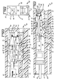
- FIG. 1 is a partial cross-sectional view of a connector including an electrical terminal disposed in a connector body, according to an exemplary embodiment of the present invention
- FIG. 2 is an end view of the connector of FIG. 1 ;
- FIG. 3 is a partial cross-sectional view of the connector of FIG. 1 , illustrating insertion of the electrical terminal into the connector body;
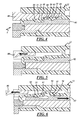
- FIG. 4 is a partial cross-sectional view of the connector body of FIG. 1 , as molded using mold tooling;
- FIG. 5 is a partial cross-sectional view illustrating initial retraction of the mold tooling from the connector body of FIG. 4 ;
- FIG. 6 is a partial cross-sectional view illustrating continued retraction of the mold tooling from the connector body of FIG. 5 .
- an electrical connector 10 includes a connector body 12 having one or more terminal cavities 14 formed therein.
- the connector body 12 includes a front face 16 and a rear face 18.
- the front face 16 has one or more front openings 20 and the rear face 18 has one or more rear openings 21, each corresponding with respective terminal cavities 14, which extend front to rear in a longitudinal direction.
- the illustrated terminal cavity 14 is defined in part by rigid walls 22, 23, 24 and opposed sidewalls 26, and extends substantially between the front and rear faces 16, 18.
- the rigid walls 22, 23, 24 are attached along their edges to other portions of the connector body 12. More specifically, the walls 22, 23, 24 are attached along at least portions of at least two of their edges and preferably along all four of their edges to prevent movement or flexing of the rigid walls 22, 23, 24.
- the rigid walls 22, 23, 24 can be end walls or partition walls of the connector body 12. It is also contemplated that one or more of the walls 22, 23, 24, could be attached along less than all four of their edges, such that the walls 22, 23, 24 are beams or the like. It is further contemplated that wall 23 and wall 24 could be integrated into a single combined wall.
- the rigid walls 22, 23, 24 can longitudinally extend at least partially between the front and rear faces 16, 18.
- the rigid wall 22 extends forward from the rear face 18 and is connected by a bridge portion to another rigid wall 23.
- the other rigid wall 24 extends forward from the rear face 18 to the front face 16 and is preferably a rigid retention wall 24 carrying a rigid, terminal retention feature 28 that extends into the terminal cavity 14.
- the retention feature 28 can be a rigid lock nib that includes a sloped surface 30 that starts nearest the rear face 18 of the connector body and terminates at a lock shoulder 32 on the retention feature 28 formed nearest the front face 16.
- Cantilevered hold-down beams 33, 35 are disposed substantially opposite with respect to the rigid retention wall 24.
- the hold-down beams 33, 35 are two in number, generally opposed to one another, flexible, and attached at their fixed ends 34, 38 to other portions of the connector body 12.
- the rigid retention wall 24 carries longitudinal retention forces
- the hold-down beams 33, 35 preferably act in concert as a hold-down spring.
- a space S is provided between another rigid wall 23 and the hold-down beams 33, 35 to facilitate movement or deflection of the hold-down beams 33, 35.
- the hold-down beams 33, 35 include a first hold-down beam 33, and a second hold-down beam 35.
- the first hold-down beam 33 is preferably attached at a fixed end 34 to one of the rigid walls 22, and is cantilevered therefrom in a forward longitudinal direction to terminate in a free end 36.
- the second hold-down beam 35 is preferably attached at a fixed end 38 to the front face 16 and is cantilevered therefrom in a rearward longitudinal direction to terminate in a free end 40.
- a terminal hold-down projection 42 may be provided on the second hold-down beam 35 and extends toward the rigid retention wall 24 at a location generally opposite the retention feature 28.
- the projection 42 may be stepped, and may also include an axially rearward projection 43 to engage the first hold-down beam 33.
- the connector body 12 is constructed and arranged for receiving an electrical terminal 44 in each of the terminal cavities 14.
- the connector body 12 is preferably composed of any suitable electrically non-conductive material, whereas the electrical terminal 44 is composed of any suitable electrically conductive material.
- the electrical terminal 44 may be any suitable type of terminal and, as shown, can be a female terminal.
- the terminal 44 may include a contact portion 46 and a crimp portion 48, and an intermediate body portion 50.
- the contact portion 46 can be open, for example to receive a male terminal, and the crimp portion 48 is constructed for attachment to a wire W.
- the terminal 44 has a first surface 54 for contact with a portion of the second hold-down beam 35, and a second surface 56 also for contact with another portion of the second hold-down beam 35.
- the terminal 44 has a relief 58, such as a recess or an aperture, for receiving the retention feature 28, and a rigid lock edge 60 associated with the relief 58 for engaging the lock shoulder 32 of the retention feature 28.
- the contact portion 46 of the terminal 44 is inserted through the rear opening 21 in the rear face 18 and into the terminal cavity 14. As best shown in FIG. 3 , an angled surface of the contact portion 46 of the terminal 44 engages the retention feature 28 and the terminal 44 rides up the sloped surface 30 thereof to lift the terminal 44 generally away from the rigid retention wall 24 and toward the hold-down beams 33, 35. As the terminal 44 rides up the sloped surface 30 of the retention feature 28, the second surface 56 of the terminal 44 engages the stepped projection 42 and the second hold-down beam 35 flexes. The second hold-down beam 35 flexes such that the rearward projection 43 thereof engages the first hold-down beam 33, which also flexes. Accordingly, there is a sliding and lifting action between the rearward projection 43 and a corresponding portion of the first hold-down beam 33.
- the hold-down beams 33, 35 are resilient such that they tend to recover their rest position under their own inherent resilient bias force. Thus, the second hold-down beam 35 flexes during terminal engagement and then engages the first hold-down beam 33.
- the inherent resilient bias forces of the hold-down beams 33, 35 result in a combined hold-down force F 2 . Both beams 33, 35 flex into the space S to accommodate the movement of the terminal 44 over the retention feature 28.
- the terminal 44 is pushed forward until the rigid lock edge 60 snaps in front of the retention feature 28 at which point the terminal 44 is forced against the rigid retention wall 24 by the combined resilient force F 2 of the hold-down beams 33, 35 such that the recess or aperture 58 overlies the retention feature 28.
- one or both of the hold-down beams 33, 35 apply a sufficient hold-down force F 1 to hold the terminal 44 in engagement with the retention feature 28 of the rigid retention wall 24 and to maintain the rigid lock edge 60 against the lock shoulder 32 of the retention feature 28, thereby preventing inadvertent dislocation and rearward withdrawal of the terminal 44 from the cavity 14.
- the stepped projection 42 rests against the front end 46 and the body 50 of the terminal 44.
- the free end 36 of the first hold-down beam 33 can rest against the free end 40 of the second hold-down beam 35 or, as shown, there can be a slight clearance therebetween. In either case, if the terminal 44 moves away from the rigid retention wall 24 and toward the other rigid walls 22, 23 the hold-down force F 2 of the one or both of the hold-down beams 33, 35 tends to keep the terminal 44 seated and engaged in the terminal cavity 14.
- the dual beams 33, 35 enable the connector body 12 to be composed of any suitable glass-filled material.
- connector bodies for small terminals for example about 0.64 to 1.2 mm, can be composed of glass-filled material to achieve desired terminal retention specifications.
- the connector body 12 can be composed of any suitable glass-filled material such as a glass-filled polyester, such as glass-filled polybutylene terephthalate (PBT).
- PBT polybutylene terephthalate
- the material may include any suitable amount of glass material and, for example, may be a 20% glass-filled PBT material. Because the dual cantilevered hold-down beams 33, 35 each undergo less strain than would a single simple beam, the present invention enables lower strain levels than conventional connector bodies with a single simple flexible hold-down beam.
- the hold-down beams 33, 35 impose at least as much force on the terminal 44 as a conventional single simple beam, but with considerably less strain thereon. Accordingly, the terminal 44 can be inserted and removed from the connector body 12 without fracturing the hold-down beams 33, 35.
- a stop 62 such as an inside surface of the front face 16, can be provided in the connector body 12 to prevent the terminal 44 from moving too far in a forward direction.
- a male terminal blade (not shown) may be inserted through the opening 20 in the front face 16 of the connector body 12 and into the open end 46 of the female terminal 44.
- Another opening 64 may be provided in the front face 16 of the connector body 12 so that a tool (not shown) may be inserted therethrough to lift the electrical terminal 44 so that the lock edge 60 can clear the retention feature 28 to allow the female terminal 44 to be removed through the rear opening 21 in the rear face 18.
- FIGS. 4 through 6 a portion of the connector body 12 is shown as molded, using mold tooling T shown in its mold fill position.
- the mold tooling T is designed and its movement timed to eliminate a die lock condition, and the connector body 12 is designed to allow the hold-down beams 33, 35 to deflect during retraction of the mold tooling T.
- the mold tooling T includes a forward core 80 between the hold-down beams 33, 35 and the rigid wall 23, and a rearward core 82 between the hold-down beams 33, 35 and the rigid retention wall 24.
- the forward core 80 includes a first surface 84 partially defining a portion of the first hold-down beam 33, a second surface 86 partially defining a portion the second hold-down beam 35, and a step 88 therebetween.
- the rearward core 82 includes a projection 90 that partially defines a portion of the free end 36 of the first hold-down beam 33, and a portion of the free end 40 of the second hold-down beam 35.
- the step 88 of the forward core 80 and the projection 90 of the rearward core 82 may be slightly spaced apart to allow connector material to fill and possibly temporarily connect the free ends 36, 40 of the hold-down beams 33, 35 to one another.
- the connector body 12 is molded with the forward and rearward cores 80, 82 in their mold-fill positions.
- extraction of the forward core 80 is initiated before extraction of the rearward core 82 is initiated. Accordingly, the forward core 80 is shown being moved from its mold fill position, while the rearward core 82 is shown stationary in its mold fill position.
- the forward core 80 is shown moved even further away from its mold fill position, while the rearward core 82 is shown in an initial extraction stage, being moved from its mold fill position.
- retraction of the forward core 80 is initiated and, then, after a predetermined delay, retraction of the rearward core 82 is initiated.
- the hold-down beams 33, 35 deflect into the space S between the beams 33, 35 and wall 23 to allow the rearward core 82 to move relative thereto, thereby avoiding a die lock condition.
- the hold-down beams 33, 35 deflect as the projection 90 of the rearward core 82 engages a projection 70 of the first hold-down beam 33 and a forward portion 92 of the rearward core 82 engages the stepped projection 42 of the second hold-down beam 35.
- the projection 70 of the first hold-down beam may be provided to guide the terminal 44 under the second hold-down beam 35 such that the terminal 44 does not catch or hang up on the second hold-down beam 35.
- the electrical connector body according to the present invention has a relatively low profile, is simple in design, easy to manufacture, provides a sufficient hold-down force on an electrical terminal, yet can be composed of any suitable glass-filled material, all of which heretofore has been absent in prior art designs.
Landscapes
- Engineering & Computer Science (AREA)
- Manufacturing & Machinery (AREA)
- Connector Housings Or Holding Contact Members (AREA)
- Switch Cases, Indication, And Locking (AREA)
Applications Claiming Priority (1)
| Application Number | Priority Date | Filing Date | Title |
|---|---|---|---|
| US11/654,823 US7384309B1 (en) | 2007-01-18 | 2007-01-18 | Electrical connector body having cantilevered terminal hold-down beams |
Publications (3)
| Publication Number | Publication Date |
|---|---|
| EP1947741A2 true EP1947741A2 (de) | 2008-07-23 |
| EP1947741A3 EP1947741A3 (de) | 2009-12-09 |
| EP1947741B1 EP1947741B1 (de) | 2011-06-15 |
Family
ID=39323061
Family Applications (1)
| Application Number | Title | Priority Date | Filing Date |
|---|---|---|---|
| EP08100148A Not-in-force EP1947741B1 (de) | 2007-01-18 | 2008-01-07 | Elektrischer Schalterkörper mit ausladenden Balken zum Niederhalten des Endgeräts |
Country Status (5)
| Country | Link |
|---|---|
| US (1) | US7384309B1 (de) |
| EP (1) | EP1947741B1 (de) |
| KR (1) | KR20080068549A (de) |
| CN (1) | CN101232135B (de) |
| AT (1) | ATE513335T1 (de) |
Cited By (1)
| Publication number | Priority date | Publication date | Assignee | Title |
|---|---|---|---|---|
| TWI750343B (zh) * | 2017-04-14 | 2021-12-21 | 日商太谷電子日本合同公司 | 電連接器 |
Families Citing this family (12)
| Publication number | Priority date | Publication date | Assignee | Title |
|---|---|---|---|---|
| US7658645B1 (en) | 2008-08-12 | 2010-02-09 | Delphi Technologies, Inc. | Electrical connector |
| US7780485B2 (en) * | 2008-08-12 | 2010-08-24 | Delphi Technologies, Inc. | Electrical connector |
| US7635286B1 (en) | 2008-10-14 | 2009-12-22 | Delphi Technologies, Inc. | Electrical connector |
| US7811126B1 (en) * | 2010-01-06 | 2010-10-12 | Aimmet Industrial Co., Ltd. | Locking connector |
| JP5508927B2 (ja) | 2010-04-22 | 2014-06-04 | 日本航空電子工業株式会社 | コネクタ及び防水コネクタ |
| US8882528B2 (en) * | 2010-12-15 | 2014-11-11 | Sumitomo Wiring Systems, Ltd. | Connector |
| US8651901B2 (en) * | 2011-05-04 | 2014-02-18 | Tyco Electronics Corporation | Electrical connector having terminal position assurance |
| US9130311B2 (en) | 2012-02-01 | 2015-09-08 | Fci Americas Technology, Llc | Electrical connector |
| JP6141612B2 (ja) * | 2012-09-21 | 2017-06-07 | 矢崎総業株式会社 | コネクタ |
| US9071016B2 (en) | 2013-10-03 | 2015-06-30 | Delphi Technologies, Inc. | Electrical connector with a sliding flexible cantilever beam terminal retainer |
| DE112016004047B4 (de) * | 2015-09-07 | 2023-09-21 | Yazaki Corporation | Verbinder |
| DE102020207331A1 (de) * | 2020-06-12 | 2021-12-16 | Aptiv Technologies Limited | Verbindergehäuse und verbinderanordnung für abgedichtete ringanschlüsse |
Citations (1)
| Publication number | Priority date | Publication date | Assignee | Title |
|---|---|---|---|---|
| US4714437A (en) | 1987-01-20 | 1987-12-22 | Ford Motor Company | Electrical connector |
Family Cites Families (10)
| Publication number | Priority date | Publication date | Assignee | Title |
|---|---|---|---|---|
| JPS5924140Y2 (ja) * | 1980-01-17 | 1984-07-17 | 平河電線株式会社 | Acアウトレツト |
| GB8827756D0 (en) * | 1988-11-28 | 1988-12-29 | Amp Great Britain | Electrical connector housing assembly |
| JPH0637581Y2 (ja) * | 1990-02-08 | 1994-09-28 | 矢崎総業株式会社 | コネクタにおける端子金具の係止機構 |
| JP2813620B2 (ja) * | 1993-08-06 | 1998-10-22 | 矢崎総業株式会社 | 防水コネクタ |
| JP3218139B2 (ja) * | 1994-02-28 | 2001-10-15 | タイコエレクトロニクスアンプ株式会社 | コネクタ |
| US5980318A (en) | 1997-06-25 | 1999-11-09 | General Motors Corporation | Connector with a flexible beam for holding a terminal down and in position |
| US5989066A (en) * | 1997-12-18 | 1999-11-23 | The Whitaker Corporation | Electrical connector with dual position latched terminal position assurance |
| US6354873B1 (en) | 1999-01-29 | 2002-03-12 | Delphi Technologies, Inc. | Snap rail and connector body combination |
| US6733306B2 (en) * | 2002-02-28 | 2004-05-11 | Tyco Electronics Corporation | Electronic module assembly apparatus, methods and articles of manufacture |
| US7048584B1 (en) | 2005-06-23 | 2006-05-23 | Delphi Technologies, Inc. | Electrical connector |
-
2007
- 2007-01-18 US US11/654,823 patent/US7384309B1/en active Active
-
2008
- 2008-01-07 EP EP08100148A patent/EP1947741B1/de not_active Not-in-force
- 2008-01-07 AT AT08100148T patent/ATE513335T1/de not_active IP Right Cessation
- 2008-01-14 KR KR1020080003711A patent/KR20080068549A/ko not_active Ceased
- 2008-01-17 CN CN2008100012840A patent/CN101232135B/zh not_active Expired - Fee Related
Patent Citations (1)
| Publication number | Priority date | Publication date | Assignee | Title |
|---|---|---|---|---|
| US4714437A (en) | 1987-01-20 | 1987-12-22 | Ford Motor Company | Electrical connector |
Cited By (1)
| Publication number | Priority date | Publication date | Assignee | Title |
|---|---|---|---|---|
| TWI750343B (zh) * | 2017-04-14 | 2021-12-21 | 日商太谷電子日本合同公司 | 電連接器 |
Also Published As
| Publication number | Publication date |
|---|---|
| CN101232135B (zh) | 2011-10-05 |
| US7384309B1 (en) | 2008-06-10 |
| ATE513335T1 (de) | 2011-07-15 |
| KR20080068549A (ko) | 2008-07-23 |
| EP1947741B1 (de) | 2011-06-15 |
| CN101232135A (zh) | 2008-07-30 |
| EP1947741A3 (de) | 2009-12-09 |
Similar Documents
| Publication | Publication Date | Title |
|---|---|---|
| US7384309B1 (en) | Electrical connector body having cantilevered terminal hold-down beams | |
| JP5754412B2 (ja) | コネクタ | |
| EP2530787B1 (de) | Steckverbinder und Montageverfahren dafür | |
| US7556539B2 (en) | Connector | |
| EP1923962B1 (de) | Stecker und Vormontageverfahren dafür | |
| EP2779317A1 (de) | Verbinder | |
| JP4555223B2 (ja) | 接続端子 | |
| EP2437357A1 (de) | Steckverbinder | |
| CN110635292B (zh) | 连接器 | |
| JP3763574B2 (ja) | コネクタ | |
| EP0954060A3 (de) | Elektrischer Verbinder mit ablenkbarem sekundären Verriegelungselement | |
| US9960517B2 (en) | Electrical contact terminal having a spring element to support a contact beam | |
| EP0978905A2 (de) | Verbinder | |
| US6817901B2 (en) | Connector | |
| JP4254482B2 (ja) | コネクタ | |
| EP2051573A2 (de) | Containerbox, elektrischer Anschlusskasten mit Containerbox und Verfahren zum Formen der Containerbox | |
| EP3503306A1 (de) | Buchsensteckergehäuse mit niederhalterippen | |
| CN115084915A (zh) | 连接器 | |
| CN105244650A (zh) | 连接器 | |
| EP1916746A2 (de) | Verbinder | |
| JP3988424B2 (ja) | コネクタ | |
| KR101424545B1 (ko) | 커넥터 | |
| JP4844153B2 (ja) | コネクタ | |
| JP2005158418A (ja) | コネクタ | |
| US20020068479A1 (en) | Tangless terminal fixed lock |
Legal Events
| Date | Code | Title | Description |
|---|---|---|---|
| PUAI | Public reference made under article 153(3) epc to a published international application that has entered the european phase |
Free format text: ORIGINAL CODE: 0009012 |
|
| AK | Designated contracting states |
Kind code of ref document: A2 Designated state(s): AT BE BG CH CY CZ DE DK EE ES FI FR GB GR HR HU IE IS IT LI LT LU LV MC MT NL NO PL PT RO SE SI SK TR |
|
| AX | Request for extension of the european patent |
Extension state: AL BA MK RS |
|
| PUAL | Search report despatched |
Free format text: ORIGINAL CODE: 0009013 |
|
| AK | Designated contracting states |
Kind code of ref document: A3 Designated state(s): AT BE BG CH CY CZ DE DK EE ES FI FR GB GR HR HU IE IS IT LI LT LU LV MC MT NL NO PL PT RO SE SI SK TR |
|
| AX | Request for extension of the european patent |
Extension state: AL BA MK RS |
|
| 17P | Request for examination filed |
Effective date: 20100609 |
|
| AKX | Designation fees paid |
Designated state(s): AT BE BG CH CY CZ DE DK EE ES FI FR GB GR HR HU IE IS IT LI LT LU LV MC MT NL NO PL PT RO SE SI SK TR |
|
| 17Q | First examination report despatched |
Effective date: 20100730 |
|
| GRAP | Despatch of communication of intention to grant a patent |
Free format text: ORIGINAL CODE: EPIDOSNIGR1 |
|
| GRAS | Grant fee paid |
Free format text: ORIGINAL CODE: EPIDOSNIGR3 |
|
| GRAA | (expected) grant |
Free format text: ORIGINAL CODE: 0009210 |
|
| AK | Designated contracting states |
Kind code of ref document: B1 Designated state(s): AT BE BG CH CY CZ DE DK EE ES FI FR GB GR HR HU IE IS IT LI LT LU LV MC MT NL NO PL PT RO SE SI SK TR |
|
| REG | Reference to a national code |
Ref country code: GB Ref legal event code: FG4D Ref country code: CH Ref legal event code: EP |
|
| REG | Reference to a national code |
Ref country code: IE Ref legal event code: FG4D |
|
| REG | Reference to a national code |
Ref country code: DE Ref legal event code: R096 Ref document number: 602008007551 Country of ref document: DE Effective date: 20110804 |
|
| REG | Reference to a national code |
Ref country code: NL Ref legal event code: VDEP Effective date: 20110615 |
|
| PG25 | Lapsed in a contracting state [announced via postgrant information from national office to epo] |
Ref country code: NO Free format text: LAPSE BECAUSE OF FAILURE TO SUBMIT A TRANSLATION OF THE DESCRIPTION OR TO PAY THE FEE WITHIN THE PRESCRIBED TIME-LIMIT Effective date: 20110915 Ref country code: SE Free format text: LAPSE BECAUSE OF FAILURE TO SUBMIT A TRANSLATION OF THE DESCRIPTION OR TO PAY THE FEE WITHIN THE PRESCRIBED TIME-LIMIT Effective date: 20110615 Ref country code: LT Free format text: LAPSE BECAUSE OF FAILURE TO SUBMIT A TRANSLATION OF THE DESCRIPTION OR TO PAY THE FEE WITHIN THE PRESCRIBED TIME-LIMIT Effective date: 20110615 Ref country code: HR Free format text: LAPSE BECAUSE OF FAILURE TO SUBMIT A TRANSLATION OF THE DESCRIPTION OR TO PAY THE FEE WITHIN THE PRESCRIBED TIME-LIMIT Effective date: 20110615 |
|
| PG25 | Lapsed in a contracting state [announced via postgrant information from national office to epo] |
Ref country code: SI Free format text: LAPSE BECAUSE OF FAILURE TO SUBMIT A TRANSLATION OF THE DESCRIPTION OR TO PAY THE FEE WITHIN THE PRESCRIBED TIME-LIMIT Effective date: 20110615 Ref country code: LV Free format text: LAPSE BECAUSE OF FAILURE TO SUBMIT A TRANSLATION OF THE DESCRIPTION OR TO PAY THE FEE WITHIN THE PRESCRIBED TIME-LIMIT Effective date: 20110615 Ref country code: AT Free format text: LAPSE BECAUSE OF FAILURE TO SUBMIT A TRANSLATION OF THE DESCRIPTION OR TO PAY THE FEE WITHIN THE PRESCRIBED TIME-LIMIT Effective date: 20110615 Ref country code: FI Free format text: LAPSE BECAUSE OF FAILURE TO SUBMIT A TRANSLATION OF THE DESCRIPTION OR TO PAY THE FEE WITHIN THE PRESCRIBED TIME-LIMIT Effective date: 20110615 Ref country code: GR Free format text: LAPSE BECAUSE OF FAILURE TO SUBMIT A TRANSLATION OF THE DESCRIPTION OR TO PAY THE FEE WITHIN THE PRESCRIBED TIME-LIMIT Effective date: 20110916 Ref country code: CY Free format text: LAPSE BECAUSE OF FAILURE TO SUBMIT A TRANSLATION OF THE DESCRIPTION OR TO PAY THE FEE WITHIN THE PRESCRIBED TIME-LIMIT Effective date: 20110615 |
|
| PG25 | Lapsed in a contracting state [announced via postgrant information from national office to epo] |
Ref country code: NL Free format text: LAPSE BECAUSE OF FAILURE TO SUBMIT A TRANSLATION OF THE DESCRIPTION OR TO PAY THE FEE WITHIN THE PRESCRIBED TIME-LIMIT Effective date: 20110615 Ref country code: BE Free format text: LAPSE BECAUSE OF FAILURE TO SUBMIT A TRANSLATION OF THE DESCRIPTION OR TO PAY THE FEE WITHIN THE PRESCRIBED TIME-LIMIT Effective date: 20110615 |
|
| PG25 | Lapsed in a contracting state [announced via postgrant information from national office to epo] |
Ref country code: EE Free format text: LAPSE BECAUSE OF FAILURE TO SUBMIT A TRANSLATION OF THE DESCRIPTION OR TO PAY THE FEE WITHIN THE PRESCRIBED TIME-LIMIT Effective date: 20110615 Ref country code: PT Free format text: LAPSE BECAUSE OF FAILURE TO SUBMIT A TRANSLATION OF THE DESCRIPTION OR TO PAY THE FEE WITHIN THE PRESCRIBED TIME-LIMIT Effective date: 20111017 Ref country code: CZ Free format text: LAPSE BECAUSE OF FAILURE TO SUBMIT A TRANSLATION OF THE DESCRIPTION OR TO PAY THE FEE WITHIN THE PRESCRIBED TIME-LIMIT Effective date: 20110615 Ref country code: IS Free format text: LAPSE BECAUSE OF FAILURE TO SUBMIT A TRANSLATION OF THE DESCRIPTION OR TO PAY THE FEE WITHIN THE PRESCRIBED TIME-LIMIT Effective date: 20111015 |
|
| PG25 | Lapsed in a contracting state [announced via postgrant information from national office to epo] |
Ref country code: PL Free format text: LAPSE BECAUSE OF FAILURE TO SUBMIT A TRANSLATION OF THE DESCRIPTION OR TO PAY THE FEE WITHIN THE PRESCRIBED TIME-LIMIT Effective date: 20110615 Ref country code: SK Free format text: LAPSE BECAUSE OF FAILURE TO SUBMIT A TRANSLATION OF THE DESCRIPTION OR TO PAY THE FEE WITHIN THE PRESCRIBED TIME-LIMIT Effective date: 20110615 Ref country code: RO Free format text: LAPSE BECAUSE OF FAILURE TO SUBMIT A TRANSLATION OF THE DESCRIPTION OR TO PAY THE FEE WITHIN THE PRESCRIBED TIME-LIMIT Effective date: 20110615 |
|
| PLBE | No opposition filed within time limit |
Free format text: ORIGINAL CODE: 0009261 |
|
| STAA | Information on the status of an ep patent application or granted ep patent |
Free format text: STATUS: NO OPPOSITION FILED WITHIN TIME LIMIT |
|
| 26N | No opposition filed |
Effective date: 20120316 |
|
| PG25 | Lapsed in a contracting state [announced via postgrant information from national office to epo] |
Ref country code: DK Free format text: LAPSE BECAUSE OF FAILURE TO SUBMIT A TRANSLATION OF THE DESCRIPTION OR TO PAY THE FEE WITHIN THE PRESCRIBED TIME-LIMIT Effective date: 20110615 |
|
| REG | Reference to a national code |
Ref country code: DE Ref legal event code: R097 Ref document number: 602008007551 Country of ref document: DE Effective date: 20120316 |
|
| PG25 | Lapsed in a contracting state [announced via postgrant information from national office to epo] |
Ref country code: MC Free format text: LAPSE BECAUSE OF NON-PAYMENT OF DUE FEES Effective date: 20120131 |
|
| REG | Reference to a national code |
Ref country code: CH Ref legal event code: PL |
|
| GBPC | Gb: european patent ceased through non-payment of renewal fee |
Effective date: 20120107 |
|
| REG | Reference to a national code |
Ref country code: IE Ref legal event code: MM4A |
|
| PG25 | Lapsed in a contracting state [announced via postgrant information from national office to epo] |
Ref country code: LI Free format text: LAPSE BECAUSE OF NON-PAYMENT OF DUE FEES Effective date: 20120131 Ref country code: GB Free format text: LAPSE BECAUSE OF NON-PAYMENT OF DUE FEES Effective date: 20120107 Ref country code: CH Free format text: LAPSE BECAUSE OF NON-PAYMENT OF DUE FEES Effective date: 20120131 |
|
| PG25 | Lapsed in a contracting state [announced via postgrant information from national office to epo] |
Ref country code: IE Free format text: LAPSE BECAUSE OF NON-PAYMENT OF DUE FEES Effective date: 20120107 |
|
| PG25 | Lapsed in a contracting state [announced via postgrant information from national office to epo] |
Ref country code: ES Free format text: LAPSE BECAUSE OF FAILURE TO SUBMIT A TRANSLATION OF THE DESCRIPTION OR TO PAY THE FEE WITHIN THE PRESCRIBED TIME-LIMIT Effective date: 20110926 |
|
| PG25 | Lapsed in a contracting state [announced via postgrant information from national office to epo] |
Ref country code: BG Free format text: LAPSE BECAUSE OF FAILURE TO SUBMIT A TRANSLATION OF THE DESCRIPTION OR TO PAY THE FEE WITHIN THE PRESCRIBED TIME-LIMIT Effective date: 20110915 |
|
| PG25 | Lapsed in a contracting state [announced via postgrant information from national office to epo] |
Ref country code: MT Free format text: LAPSE BECAUSE OF FAILURE TO SUBMIT A TRANSLATION OF THE DESCRIPTION OR TO PAY THE FEE WITHIN THE PRESCRIBED TIME-LIMIT Effective date: 20110615 |
|
| PG25 | Lapsed in a contracting state [announced via postgrant information from national office to epo] |
Ref country code: TR Free format text: LAPSE BECAUSE OF FAILURE TO SUBMIT A TRANSLATION OF THE DESCRIPTION OR TO PAY THE FEE WITHIN THE PRESCRIBED TIME-LIMIT Effective date: 20110615 |
|
| PG25 | Lapsed in a contracting state [announced via postgrant information from national office to epo] |
Ref country code: LU Free format text: LAPSE BECAUSE OF NON-PAYMENT OF DUE FEES Effective date: 20120107 |
|
| PG25 | Lapsed in a contracting state [announced via postgrant information from national office to epo] |
Ref country code: HU Free format text: LAPSE BECAUSE OF FAILURE TO SUBMIT A TRANSLATION OF THE DESCRIPTION OR TO PAY THE FEE WITHIN THE PRESCRIBED TIME-LIMIT Effective date: 20080107 |
|
| REG | Reference to a national code |
Ref country code: FR Ref legal event code: PLFP Year of fee payment: 9 |
|
| REG | Reference to a national code |
Ref country code: FR Ref legal event code: PLFP Year of fee payment: 10 |
|
| REG | Reference to a national code |
Ref country code: FR Ref legal event code: PLFP Year of fee payment: 11 |
|
| REG | Reference to a national code |
Ref country code: DE Ref legal event code: R081 Ref document number: 602008007551 Country of ref document: DE Owner name: APTIV TECHNOLOGIES LIMITED, BB Free format text: FORMER OWNER: DELPHI TECHNOLOGIES, INC., TROY, MICH., US |
|
| PGFP | Annual fee paid to national office [announced via postgrant information from national office to epo] |
Ref country code: DE Payment date: 20220124 Year of fee payment: 15 |
|
| PGFP | Annual fee paid to national office [announced via postgrant information from national office to epo] |
Ref country code: IT Payment date: 20220125 Year of fee payment: 15 Ref country code: FR Payment date: 20220121 Year of fee payment: 15 |
|
| REG | Reference to a national code |
Ref country code: DE Ref legal event code: R119 Ref document number: 602008007551 Country of ref document: DE |
|
| PG25 | Lapsed in a contracting state [announced via postgrant information from national office to epo] |
Ref country code: DE Free format text: LAPSE BECAUSE OF NON-PAYMENT OF DUE FEES Effective date: 20230801 |
|
| PG25 | Lapsed in a contracting state [announced via postgrant information from national office to epo] |
Ref country code: FR Free format text: LAPSE BECAUSE OF NON-PAYMENT OF DUE FEES Effective date: 20230131 |
|
| PG25 | Lapsed in a contracting state [announced via postgrant information from national office to epo] |
Ref country code: IT Free format text: LAPSE BECAUSE OF NON-PAYMENT OF DUE FEES Effective date: 20230107 |