EP1947746A2 - Modulares Verfahren und System zum Anschluss eines isolierten Buskabelbaums - Google Patents
Modulares Verfahren und System zum Anschluss eines isolierten Buskabelbaums Download PDFInfo
- Publication number
- EP1947746A2 EP1947746A2 EP08100751A EP08100751A EP1947746A2 EP 1947746 A2 EP1947746 A2 EP 1947746A2 EP 08100751 A EP08100751 A EP 08100751A EP 08100751 A EP08100751 A EP 08100751A EP 1947746 A2 EP1947746 A2 EP 1947746A2
- Authority
- EP
- European Patent Office
- Prior art keywords
- assembly
- bridge
- insulative
- cable harness
- bus bars
- Prior art date
- Legal status (The legal status is an assumption and is not a legal conclusion. Google has not performed a legal analysis and makes no representation as to the accuracy of the status listed.)
- Withdrawn
Links
- 238000000034 method Methods 0.000 title description 6
- 230000000712 assembly Effects 0.000 claims abstract description 32
- 238000000429 assembly Methods 0.000 claims abstract description 32
- 239000000463 material Substances 0.000 claims abstract description 9
- 239000004033 plastic Substances 0.000 claims description 6
- 238000003780 insertion Methods 0.000 description 5
- 230000037431 insertion Effects 0.000 description 5
- PXHVJJICTQNCMI-UHFFFAOYSA-N Nickel Chemical compound [Ni] PXHVJJICTQNCMI-UHFFFAOYSA-N 0.000 description 4
- 239000004020 conductor Substances 0.000 description 4
- 239000007787 solid Substances 0.000 description 4
- 238000009434 installation Methods 0.000 description 3
- 229920006104 Amodel® Polymers 0.000 description 2
- RYGMFSIKBFXOCR-UHFFFAOYSA-N Copper Chemical compound [Cu] RYGMFSIKBFXOCR-UHFFFAOYSA-N 0.000 description 2
- 229910000881 Cu alloy Inorganic materials 0.000 description 2
- KDLHZDBZIXYQEI-UHFFFAOYSA-N Palladium Chemical compound [Pd] KDLHZDBZIXYQEI-UHFFFAOYSA-N 0.000 description 2
- 229910052802 copper Inorganic materials 0.000 description 2
- 239000010949 copper Substances 0.000 description 2
- 229910052759 nickel Inorganic materials 0.000 description 2
- 239000012811 non-conductive material Substances 0.000 description 2
- BASFCYQUMIYNBI-UHFFFAOYSA-N platinum Chemical compound [Pt] BASFCYQUMIYNBI-UHFFFAOYSA-N 0.000 description 2
- BQCADISMDOOEFD-UHFFFAOYSA-N Silver Chemical compound [Ag] BQCADISMDOOEFD-UHFFFAOYSA-N 0.000 description 1
- ATJFFYVFTNAWJD-UHFFFAOYSA-N Tin Chemical compound [Sn] ATJFFYVFTNAWJD-UHFFFAOYSA-N 0.000 description 1
- 239000000956 alloy Substances 0.000 description 1
- PCHJSUWPFVWCPO-UHFFFAOYSA-N gold Chemical compound [Au] PCHJSUWPFVWCPO-UHFFFAOYSA-N 0.000 description 1
- 229910052737 gold Inorganic materials 0.000 description 1
- 239000010931 gold Substances 0.000 description 1
- 238000004519 manufacturing process Methods 0.000 description 1
- 238000002844 melting Methods 0.000 description 1
- 230000008018 melting Effects 0.000 description 1
- 238000012986 modification Methods 0.000 description 1
- 230000004048 modification Effects 0.000 description 1
- 229910052763 palladium Inorganic materials 0.000 description 1
- 229910052697 platinum Inorganic materials 0.000 description 1
- 238000000926 separation method Methods 0.000 description 1
- 229910052709 silver Inorganic materials 0.000 description 1
- 239000004332 silver Substances 0.000 description 1
Images





Classifications
-
- H—ELECTRICITY
- H01—ELECTRIC ELEMENTS
- H01R—ELECTRICALLY-CONDUCTIVE CONNECTIONS; STRUCTURAL ASSOCIATIONS OF A PLURALITY OF MUTUALLY-INSULATED ELECTRICAL CONNECTING ELEMENTS; COUPLING DEVICES; CURRENT COLLECTORS
- H01R25/00—Coupling parts adapted for simultaneous co-operation with two or more identical counterparts, e.g. for distributing energy to two or more circuits
- H01R25/16—Rails or bus-bars provided with a plurality of discrete connecting locations for counterparts
- H01R25/161—Details
- H01R25/162—Electrical connections between or with rails or bus-bars
-
- H—ELECTRICITY
- H01—ELECTRIC ELEMENTS
- H01R—ELECTRICALLY-CONDUCTIVE CONNECTIONS; STRUCTURAL ASSOCIATIONS OF A PLURALITY OF MUTUALLY-INSULATED ELECTRICAL CONNECTING ELEMENTS; COUPLING DEVICES; CURRENT COLLECTORS
- H01R25/00—Coupling parts adapted for simultaneous co-operation with two or more identical counterparts, e.g. for distributing energy to two or more circuits
- H01R25/16—Rails or bus-bars provided with a plurality of discrete connecting locations for counterparts
- H01R25/168—Rails or bus-bars provided with a plurality of discrete connecting locations for counterparts the connecting locations being situated away from the rail or bus-bar
-
- Y—GENERAL TAGGING OF NEW TECHNOLOGICAL DEVELOPMENTS; GENERAL TAGGING OF CROSS-SECTIONAL TECHNOLOGIES SPANNING OVER SEVERAL SECTIONS OF THE IPC; TECHNICAL SUBJECTS COVERED BY FORMER USPC CROSS-REFERENCE ART COLLECTIONS [XRACs] AND DIGESTS
- Y10—TECHNICAL SUBJECTS COVERED BY FORMER USPC
- Y10T—TECHNICAL SUBJECTS COVERED BY FORMER US CLASSIFICATION
- Y10T29/00—Metal working
- Y10T29/53—Means to assemble or disassemble
- Y10T29/5313—Means to assemble electrical device
Definitions
- the present invention is directed to a modular solution of bringing power into a panel assembly bus bar while being insulated and also accommodate multiple different configurations of the number of bus bars to be jumpered between.
- Panel assembly bus bars typically are installed such that the entire length of the bus bar is exposed and not protected.
- the exposed bus bar creates the opportunity for a foreign object to fall across the multiple bars and cause a short circuit, thereby damaging the bus bars as well as the panel assembly and other electrical equipment supported by the panel assembly.
- One current system for preventing outside objects from contacting the bus bars is to place a covering across the entire panel. However, this covering does not prevent any objects from within the panel system from falling onto the bus bars and causing a short.
- the problem to be solved is a need for a type of protection for the bus bars that will prevent objects from contacting the bus bars, while providing a secure contact and adequate conductivity of the bars.
- the solution is provided by an apparatus for terminating a bus bar assembly having a cable harness assembly with an insulative harness component, a plurality of conductive wires partially recessed within the insulative harness component, the wires having terminals on a bottom of the insulative harness component and extending from at least one side of the insulative harness component, a plurality of first apertures disposed along a top surface of the cable harness assembly for receiving a plurality of fasteners.
- the apparatus also includes at least one bridge assembly having an insulative bridge component, a plurality of first apertures along a top surface of the at least one bridge assembly for receiving fasteners, a plurality of insulative protrusions extending away from the at least one bridge assembly, a plurality of bus bars disposed on a bottom of the at least one insulative bridge component, the plurality of insulative protrusions securing the plurality of bus bars along the bottom of the at least one insulative bridge component.
- the at least one bridge assembly partially covers the plurality of bus bars and the cable harness assembly is configured to cover an exposed portion of the plurality of bus bars, wherein the plurality of bus bars contacts the terminals on the bottom of the insulative harness component to create an electrically conductive connection.
- An advantage of the present invention is the ability to provide power to a panel through a modular system.
- Yet another advantage of the present invention is a provision of multiple bus bar assembly, depending upon need.
- Still another advantage of the present invention is that it permits use of overmolded cable harnesses to provide easy bolt-in assemblies.
- Yet another advantage of the present invention is the ability to construct the bridges from either side of the assembly without damaging the wires.
- Another advantage of the present invention is the variety of multiple positions made available.
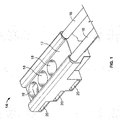
- Figure 1 illustrates the cable harness of the present invention.
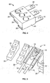
- FIG. 2 illustrates the bridge assembly of the present invention.
- Figure 3 illustrates the cable harness disposed on a board-mounted connector.
- Figure 4 illustrates the bridge assembly and the cable harness of the present invention.
- Figure 5 illustrates the bridge assembly as partially assembled to the cable harness of the present invention.
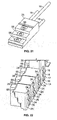
- Figure 6 illustrates a multiple bus bar termination of one embodiment of the present invention.
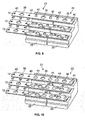
- Figure 7 illustrates a 4-position Bus Bar with molded bridges shifted left.
- Figure 8 illustrates a 4-position bus bar with molded bridges shifted right.
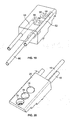
- Figure 9 illustrates a 3-position bus bar assembly prior to the heat stake.
- Figure 10 illustrates the 3-position bus bar assembly of Figure 9 after the heat stake.
- Figure 11 illustrates the installation method of the bus bar assemblies.
- Figure 12 illustrates the installation method of the bus bar assemblies where the cable harness assembly is installed.
- Figure 13 illustrates the cable harness as installed to the right of the bridge assemblies.
- Figure 14 illustrates the cable harness as installed to the left of the bridge assemblies.
- Figure 15 is a view of the bus bar assembly from the view of the PC board.
- Figure 16 is the left wire contact used in the cable harness assembly of the present invention.
- Figure 17 is the center wire contact used in the cable harness assembly of the present invention.
- Figure 18 is the right wire contact used in the cable harness assembly of the present invention.
- Figure 19 illustrates the three cable assemblies as assembled in the cable harness assembly.
- Figure 20 illustrates the top view of the cable harness assembly.
- Figure 21 illustrates the bottom view of the cable harness assembly.
- Figure 22 illustrates the molded extensions on the present invention.
- Figure 23 illustrates a cable harness assembly disposed between multiple bridge assemblies.
- Bus bar assemblies can be used to conduct single phase or three-phase power to various electrical components.
- the present invention may be used with any application that requires the use of bus bar assemblies.
- bus bar assemblies are exposed to foreign objects that may contact them and short the electrical connection and cause damage to the bus bars, and other equipment that is electrically connected to or in contact with them. None is used to protect the bus bars from contacting an object and causing an electrical short.
- Figure 1 illustrates a portion of one embodiment of the present invention that protects the bus bar 12 from being contacted by an extraneous object and causing an electrical short when assembled.
- the cable harness assembly 14 is configured with an insulative component 17 and wires 16 secured with a connection to terminals (not shown) inside the cable harness 14.
- the cable harness 14 has three apertures 18 which accommodate the insertion of screws (not shown) or other hardware.
- Three other apertures 20 are disposed along the side of the cable harness 14 that accommodate the insertion of the bus bars of the bridge assembly 22 illustrated in Figure 2 .
- the bridge assembly 22 also contains three apertures 24 that accommodate the insertion of screws (not shown) or other hardware.
- bus bars 12 protrude from the bridge assembly 22, which mount into the apertures 20 along the side of the cable harness 14 ( Figure 1 ).
- the bridge assembly 22 also has apertures 26 along the opposite side of the bus bars 12 which accommodate the insertion of bus bars 12 from another bridge assembly 22, if necessary.
- the cable harness 14 ( Figure 1 ) and the bridge assembly 22 completely encapsulate the bus bars 12 and protect the bus bars 12 from contacting any foreign object that may cause an electrical short.
- Both the cable harness 14 ( Figure 1 ) and the bridge assembly 22 overmolds are manufactured from a non-conductive material capable of enduring high temperatures.
- Figure 3 illustrates the cable harness 14 as disposed on a portion of the board-mounted connector 28.
- the cable harness 14 is designed to lie on conductive members of the board-mounted connector 28 such that the apertures 30 in the connector 28 align with the screw apertures 18 of the cable harness 14.
- the method of application of the cable harness 14 and bridge assembly 22 to the connector 28 shown in Figures 5 and 6 includes placing the cable harness 14 on the connector 28 ( Figure 3 ) and inserting the bus bars 12 of the first bridge assembly 22 into the side apertures 20 of the cable assembly 14 ( Figure 4 ). As the bus bars 12 are inserted into the side apertures 20 of the cable assembly 14, apertures 38 of the bus bars 12 align with the apertures 18 of the cable assembly 14 ( Figure 5 ).
- a second bridge assembly 22 is inserted into the first bridge assembly 22 as shown in Figure 6 .
- This insertion is performed in the same manner as the first bridge assembly 22 was inserted into the cable harness 14 in Figures 4 and 5 .
- the bus bars 12 of the second bridge assembly 22 are inserted into the apertures 26 of the first bridge assembly 22 until the bus bar apertures 38 align with the screw apertures 24.
- a screw (not shown) or other tool is inserted into the aperture to secure the bridge assemblies 22 in place.
- Figure 6 shows a maximum of three bridge assemblies 22 connected to one cable harness 14, any number of multiple bridge assemblies 22 may be used in connection with one another. Further, as Figure 6 shows, as few as one bridge assembly 22 may be used in connection with one cable harness 14, or a cable harness 14 may be used alone without a bridge assembly 22.
- the cable harness 14 and bridge assembly 22 shown in Figures 1-6 preferably accommodate the use of up to six terminal connections, but are not limited to six connections.
- three bus bars 12 are shown in all Figures, however as few as one bus bar 12 may be used, and an infinite amount of a plurality of bus bars 12 may be used as well, subject to the limitations discussed above.
- the preferred application is for a three-phase, AC electrical application, however, a single phase, DC electrical application may also apply, as well as having multiple bus bars carrying different levels of current. For example, one bus bar may carry ten amperes, the second may carry twenty amperes, and the third may carry thirty amperes, however any configuration may be used.
- the screw apertures are preferably designed to accommodate a screw, in which the screw head is recessed below the top surface of the cable harness 14 or bridge assembly 22.
- any type of tool or equipment capable of being conductive and fitting into the apertures 18, 24 may be used.
- the terminals 56 ( Figures 16-18 ) are welded to the wires 16 and are preferably constructed of a copper alloy or C110 copper material, however, any type of electrically conductive material may be used for the terminals 56 or the wires 16 in the cable harness 14. After the wire terminal assemblies are assembled, they are overmolded, encapsulating them in a non-conductive material as discussed previously.
- FIG. 7 and 8 A preferred embodiment of the present invention is illustrated in Figures 7 and 8 .
- This embodiment includes bus bars 12 that are not fully encompassed by a plastic enclosure as in the first embodiment.
- An insulative bridge component 25 is used that has three screw apertures 34 that align with the apertures 38 of the bus bar 12.
- the insulative bridge component is manufactures from a plastic or other suitable insulative material.
- Amodel ® plastic manufactured by Solvey Advanced Plymers is used.
- Figures 7 and 8 illustrate the use of three bridge components 25 and three bus bars 12 to make a bridge assembly 23, as few as one bridge 25 may be used.
- one to five bridge components 25 are used in an application, however, any number of bridge components 25 may be used.
- Figures 7 and 8 illustrate that the bridge components 25 may be assembled where the first bridge 25 is placed to the left-most end of the bus bar 12. The other remaining bridge 25 are then assembled to the right of the first bridge 25.
- Figure 8 illustrates a bridge assembly 23 where the first bridge is placed to the right-most end of the bus bar 12. The other remaining bridges 25 are then assembled to the left of the first bridge 25.
- the preferred embodiment permits the arrangement of the bridge components 25 where the bridges 25 can be shifted either to the left, right or end positions as required, for maximum flexibility of the installation where the open position would accept a cable assembly 14.
- FIG 9 illustrates an underside view of the bridge assembly 23 prior to the final assembly of the present invention.
- the bus bars 12 are stamped having screw apertures 38 and protrusion apertures 40.
- the screw apertures 38 are sized such that a screw (not shown) or other fastener may fit through the aperture 38 to enable mounting in the application.
- the protrusion apertures 40 are sized such that the protrusions 42 on the bridge components 25 may fit through the apertures 40.
- the protrusions 42 are molded features of the bridge components 25 and are part of the unitary device of the bridge components 25, which is made from the same Amodel ® plastic or other suitable insulative material as the bridge components 25.
- the protrusions 42 fit through the protrusion apertures 40 locating the bus bars 12 until a heat stake process is applied to the protrusions 42. During the heat stake, the portion of the protrusions 42 that rise above the bus bar 12 are formed into caps 44 that secure the bus bar 12 to the bridge components 25, thereby creating the bridge assembly 23, as shown in Figure 10 .
- Figure 11 illustrates a bridge assembly 23 as it rests on the board-mounted connectors 28.
- Figure 11 illustrates a four-hole bridge assembly 23, comprised of three four-hole bus bars 12, and three bridge components 25, it is understood however, that any number of bridge components 25 and bus bars 12 can be used.
- Figure 11 also illustrates the method in which the bridge assemblies 23 are assembled. The bridge assembly 23 is placed on the board-mounted connectors first, and then the screws (not shown) or other equipment are secured in the screw apertures 34. Next, as shown in Figure 12 , the cable harness 14 is placed on the remaining exposed portion 48 ( Figure 11 ) of the bus bar 12.
- Screws (not shown) or other equipment are placed in the screw apertures 34, which secure the cable harness 14 in place to the board-mounted connectors 28 and make an electrical connection between the terminals 56 of the cable assembly 14 and the bus bar 12.
- the screw heads (not shown) are recessed into the bridge components 25 and the cable harness 14 to ensure that no foreign objects can contact the screw heads to short out the electrical connection and cause damage to any portion of the apparatus.
- This arrangement of the cable harness 14 and bridge assembly 23 can be arranged and structured so that the cable harness 14 can be secured to the right of the bridge components 25 as shown in Figure 13 , or such that the cable harness 14 is secured to the left of the bridge components 25, as shown in Figure 14 , or somewhere in the middle, with bridge components 25 to either side of an open position 48 as shown in Figure 23 .
- Figure 15 illustrates a board view of the assembly 50.
- the board has been removed to illustrate the arrangement.
- Figure 15 specifically illustrates a four-position assembly, however it is understood that any numbered position of assembly may be used.
- the screw apertures 38 of bus bars 12 are aligned with the screw apertures 30 of the board-mounted connectors 28.
- the caps 44 of the protrusions 42 can be seen between the board-mounted connectors 28, and are securing the bus bars 12 to the bridge components 25.
- Figures 16, 17 and 18 illustrate the cable assemblies used within the cable harness (not shown).
- Figure 16 illustrates the left cable assembly 54, which includes a wire 16 and a terminal 56.
- the terminal 56 is configured such that the wire 16 is to the left of the terminal 56.
- Figure 17 illustrates the center cable assembly 60, which includes a wire 16 and a terminal 56 also.
- the terminal 56 is configured such that the wire 16 extends directly from the terminal 56.
- Figure 18 illustrates the right cable assembly 62, which includes a wire 16 and a terminal 56.
- the terminal 56 is configured such that the wire is disposed to the right of the terminal 56.
- Each terminal 56 has an aperture 58, which is configured such that a screw or other equipment can fit through.
- the aperture 58 of the terminal 56 fits in alignment with the screw aperture 18 of the cable harness 14.
- Each terminal 56 is stamped from a suitable conductive material, preferably copper or a copper alloy material.
- the terminal 56 is then preferably plated with any other suitable conductive material, or combination of materials such as gold, silver, platinum, palladium, or nickel, although tin over nickel is preferred.
- Figure 19 illustrates the cable assemblies 54, 60, 62 as arranged and disposed in the cable harness assembly 14.
- the right cable assembly 62 is disposed furthest back and in line with the first screw aperture 18.
- the wire 16 exits the cable harness 14 at a different elevation, but substantially parallel with respect to the other wires 16.
- the left assembly 54 is disposed in line with the second screw aperture 18.
- the wire 16 exits the cable harness below the wire 16 from the right cable assembly 62, but above the wire 16 from the center cable assembly 60.
- the left cable assembly 54 and the right cable assembly 62 may be reversed, where the left cable assembly 54 is placed furthest back and in line with the first screw aperture and the right cable assembly 62 is placed in line with the second screw aperture 18.
- the center assembly 60 is disposed within the cable harness 14 in line with the third screw aperture 18.
- the wire 16 exits the cable harness below both the wires 16 from the right and left assemblies 62, 54. All three assemblies 54, 60, 62 are secured in their relative positions by overmolding insulative material around the assemblies 54, 60, 62, creating a cable harness 14.
- a screw not shown
- the screw forces contact between the terminals 56, and the bus bars 12 to create an electrical connection, and secures the cable harness 14 to the board-mounted connectors 28.
- Figure 20 illustrates the cable harness assembly 14 in top view where the terminals 56 are shown being disposed in line with the screw aperture 18.
- the terminals 56 are exposed at the bottom of the screw aperture 18 having a rim 64 that allows a screw (not shown) or other equipment to make a solid electrical connection when in place.
- Figure 21 illustrates the bottom view of the cable harness assembly 14.
- the terminals 56 of cable assemblies 54, 60, 62 are exposed on the bottom of the harness 14 to allow a solid electrical connection with the bus bars 12 that the harness 14 will rest upon when assembled to a bridge assembly.
- the bottom of the harness 14 is shaped with steps in order to receive the shape of some board-mounted connectors (not shown) and to make solid connections with the bus bars (not shown). In other embodiments, steps may not be present.
- the bottom of the harness 14 rests either on the bus bars (not shown) that are lying on the board (not shown) or, in the case where a cable harness 14 is assembled to a single board-mounted connector 28 without being connected to a bridge assembly 23, terminals 56 of cable harness 14 will rest directly on, and be secured to the conductive members of board-mounted connector 28.
- the exposed terminals 56 are forced to make a solid connection with the bus bars (not shown) or conductive member of the board-mounted connector by virtue of the screw or other fastening device.
- the screw (not shown) or other equipment fits through the apertures 18 ( Figure 20 ), through the apertures 58 in the terminals 56 and through the bus bars (not shown) and into the conductive members of the board-mounted connectors (not shown). Not only does the screw (not shown) secure the harness 14 to the board-mounted connectors (not shown), but since the screw is electrically conductive, it also provides another means to electrically connect the bus bars (not shown) to the terminals 56, and therefore the wires 16. However, a non-conductive fastener could be substituted as long as a reliable connection between the bus bar and exposed portion of the plug assembly (shown in Figure 21 ) is maintained by securing harness 14 to the bus bar.
- Figure 22 illustrates an alternate embodiment of the present invention.
- a small gap is present between adjacent bridge components 25 and cable harnesses 14 to allow for assembly tolerances and potential thermal expansion. Though it is not likely, small pieces of conductive material could pass through the gap, contact the bus bar assembly and cause an electrical short.
- the cable harness 14 and the bridge assemblies 23 may be constructed to have molded extensions 66 at the bottom to further eliminate any foreign object contact with the bus bars that are partially exposed on the underside of the bridge assemblies 23 and cable harness 14 or from entering the small gaps between the adjacent bridge assemblies 23 and cable harness 14.
- the molded extensions 66 extend past the board-mounted connectors 28 and create a shield or protection that prevents any foreign objects from being trapped between the board 46 and the bottom side of the bridge assembly 23 or cable harness 14. With the extensions, both the top and the bottom of the bus bars 12 are protected from foreign objects making contact and causing a short or other damage.
- the bridge and cable harness assemblies preferably are molded out of inexpensive plastic or other similar insulative material that is capable of sustaining heat generated by the bus bars without melting or deforming. They are easily assembled into place and easily replaced or removed as necessary. Thus, the bridge assembly and cable harness are inexpensive for manufacturing costs as well as assembly and replacement costs.
Landscapes
- Connections By Means Of Piercing Elements, Nuts, Or Screws (AREA)
- Coupling Device And Connection With Printed Circuit (AREA)
Applications Claiming Priority (1)
| Application Number | Priority Date | Filing Date | Title |
|---|---|---|---|
| US11/625,633 US7497711B2 (en) | 2007-01-22 | 2007-01-22 | Modular method and system for insulated bus bar cable harness termination concept |
Publications (2)
| Publication Number | Publication Date |
|---|---|
| EP1947746A2 true EP1947746A2 (de) | 2008-07-23 |
| EP1947746A3 EP1947746A3 (de) | 2010-04-07 |
Family
ID=39226848
Family Applications (1)
| Application Number | Title | Priority Date | Filing Date |
|---|---|---|---|
| EP08100751A Withdrawn EP1947746A3 (de) | 2007-01-22 | 2008-01-22 | Modulares Verfahren und System zum Anschluss eines isolierten Buskabelbaums |
Country Status (2)
| Country | Link |
|---|---|
| US (1) | US7497711B2 (de) |
| EP (1) | EP1947746A3 (de) |
Families Citing this family (11)
| Publication number | Priority date | Publication date | Assignee | Title |
|---|---|---|---|---|
| ITBG20060035A1 (it) * | 2006-07-06 | 2008-01-07 | Abb Service Srl | Elemento di isolamento di barre conduttrici e dispositivo di isolamento e supporto di barre conduttrici comprendente tale elemento. |
| US20110017506A1 (en) * | 2009-07-22 | 2011-01-27 | Selvin Kao | Modular over-mold harness |
| CA2858865C (en) * | 2011-12-14 | 2016-07-12 | Dula-Werke Dustmann & Co. Gmbh | Device for supplying electrical energy to a load and system therefor |
| USD697032S1 (en) * | 2012-02-09 | 2014-01-07 | Sumitomo Electric Industries, Ltd. | Relay bus bar with built-in current sensor |
| US8608496B2 (en) * | 2012-04-25 | 2013-12-17 | Pratt & Whitney Canada Corp. | Connector for multi-phase conductors |
| US10461483B2 (en) * | 2017-11-04 | 2019-10-29 | Architectural busSTRUT Corporation | Strut end condition, end block, and connector |
| KR102177694B1 (ko) * | 2017-11-06 | 2020-11-11 | 주식회사 엘지화학 | 버스바 어셈블리를 포함하는 배터리 모듈 |
| FR3082140B1 (fr) | 2018-06-06 | 2021-07-02 | Latelec | Outillage de surmoulage modulaire de toron de cables et procede de gainage utilisant un tel outillage |
| CN109149194A (zh) * | 2018-10-17 | 2019-01-04 | 上海思方电气技术有限公司 | 一种预埋式固定桥接电连接器 |
| US11095055B2 (en) * | 2019-12-20 | 2021-08-17 | Raytheon Company | Terminal block and terminal block assembly for medium to high voltage applications |
| CN112484001B (zh) * | 2020-11-30 | 2026-03-31 | 赛尔富电子有限公司 | 一种嵌入式货架取电系统 |
Family Cites Families (11)
| Publication number | Priority date | Publication date | Assignee | Title |
|---|---|---|---|---|
| FR2682824B1 (fr) * | 1991-10-16 | 1993-11-19 | Normabarre | Element modulaire de canalisation de distribution d'energie electrique. |
| US5197903A (en) * | 1992-03-02 | 1993-03-30 | Amp Incorporated | Firewall connector |
| US5292257A (en) * | 1992-07-23 | 1994-03-08 | Henry Milan | Modular outlet strip |
| FR2715775B1 (fr) * | 1994-01-28 | 1996-04-12 | Mecelec Ind | Dispositif de raccordement électrique de type modulaire. |
| US6191948B1 (en) * | 1998-01-29 | 2001-02-20 | Ellenberger & Poensgen Gmbh | Power supply device |
| FR2779279B1 (fr) * | 1998-05-26 | 2000-07-07 | Cahors App Elec | Barre de distribution d'energie electrique |
| US6045399A (en) * | 1998-11-18 | 2000-04-04 | Yu; Tsung-I | Combination outlet strip |
| FR2818024A1 (fr) * | 2000-12-08 | 2002-06-14 | Seifel Sa | Connecteur electrique destine a etre utilise dans la distribution du courant basse tension d'un reseau electrique |
| FR2818023B1 (fr) * | 2000-12-08 | 2003-02-14 | Seifel Sa | Platine de raccordement electrique destinee a etre utilisee dans la distribution du courant basse tension d'un reseau electrique |
| US20070072476A1 (en) * | 2005-08-24 | 2007-03-29 | Henry Milan | Universal serial bus hub |
| US7607928B2 (en) * | 2006-01-27 | 2009-10-27 | Schriefer Tavis D | Expanding space saving power strip |
-
2007
- 2007-01-22 US US11/625,633 patent/US7497711B2/en active Active
-
2008
- 2008-01-22 EP EP08100751A patent/EP1947746A3/de not_active Withdrawn
Also Published As
| Publication number | Publication date |
|---|---|
| EP1947746A3 (de) | 2010-04-07 |
| US20080173479A1 (en) | 2008-07-24 |
| US7497711B2 (en) | 2009-03-03 |
Similar Documents
| Publication | Publication Date | Title |
|---|---|---|
| US7497711B2 (en) | Modular method and system for insulated bus bar cable harness termination concept | |
| US7663466B1 (en) | Corner-mounted battery fuse | |
| RU2547454C2 (ru) | Система для подключения электрических токопроводящих дорожек к полюсным разъемам совместно подключенных элементов | |
| RU2195752C2 (ru) | Соединительная клемма для электропроводов | |
| CN101114737B (zh) | 包括编码装置的端子板 | |
| RU2139615C1 (ru) | Модуль ввода/вывода для шины данных | |
| US20090221191A1 (en) | Electrical terminal block | |
| US12142881B2 (en) | Charging socket with interface | |
| US5032092A (en) | Power distribution block | |
| WO2008127555A2 (en) | Devices, systems, and methods for coupling electrical conductors | |
| CN103038948A (zh) | 电连接母线 | |
| JP6581958B2 (ja) | 電圧検出構造および電圧検出モジュール | |
| WO2011126140A1 (en) | Fuse unit | |
| US10797452B2 (en) | Electrical device and grounding method for such a device | |
| WO2010146525A1 (en) | Low cost clamp for connection of electric wires or cables on printed circuits | |
| CN104521075B (zh) | 用于车辆装置的互连组件以及互连方法 | |
| US6899562B1 (en) | Grounding apparatus for an electronic module | |
| RU2007105133A (ru) | Вставное устройство защиты от перенапряжений | |
| KR100594909B1 (ko) | 분,배전반용 주차단기와 모선부스바의 접속장치 | |
| GB1584638A (en) | Multiway connector and screening partition | |
| WO2026061789A1 (en) | Auxiliary device with various installation options | |
| US12230903B2 (en) | Connecting element for mounting an electrical circuit board to a flat electrical conductor | |
| EP2250709B1 (de) | Netzstecker | |
| EP3817163B1 (de) | Leiteranordnung für ein stromverteilungssystem | |
| US20250132531A1 (en) | Contact insert for an industrial connector |
Legal Events
| Date | Code | Title | Description |
|---|---|---|---|
| PUAI | Public reference made under article 153(3) epc to a published international application that has entered the european phase |
Free format text: ORIGINAL CODE: 0009012 |
|
| AK | Designated contracting states |
Kind code of ref document: A2 Designated state(s): AT BE BG CH CY CZ DE DK EE ES FI FR GB GR HR HU IE IS IT LI LT LU LV MC MT NL NO PL PT RO SE SI SK TR |
|
| AX | Request for extension of the european patent |
Extension state: AL BA MK RS |
|
| PUAL | Search report despatched |
Free format text: ORIGINAL CODE: 0009013 |
|
| AK | Designated contracting states |
Kind code of ref document: A3 Designated state(s): AT BE BG CH CY CZ DE DK EE ES FI FR GB GR HR HU IE IS IT LI LT LU LV MC MT NL NO PL PT RO SE SI SK TR |
|
| AX | Request for extension of the european patent |
Extension state: AL BA MK RS |
|
| AKY | No designation fees paid | ||
| REG | Reference to a national code |
Ref country code: DE Ref legal event code: 8566 |
|
| STAA | Information on the status of an ep patent application or granted ep patent |
Free format text: STATUS: THE APPLICATION IS DEEMED TO BE WITHDRAWN |
|
| 18D | Application deemed to be withdrawn |
Effective date: 20101008 |