EP1947794A1 - Dispositif et procede de reception de signal de multiplexage a division de frequence orthogonale - Google Patents
Dispositif et procede de reception de signal de multiplexage a division de frequence orthogonale Download PDFInfo
- Publication number
- EP1947794A1 EP1947794A1 EP06746260A EP06746260A EP1947794A1 EP 1947794 A1 EP1947794 A1 EP 1947794A1 EP 06746260 A EP06746260 A EP 06746260A EP 06746260 A EP06746260 A EP 06746260A EP 1947794 A1 EP1947794 A1 EP 1947794A1
- Authority
- EP
- European Patent Office
- Prior art keywords
- symbol
- interpolation
- timing
- generated
- time
- Prior art date
- Legal status (The legal status is an assumption and is not a legal conclusion. Google has not performed a legal analysis and makes no representation as to the accuracy of the status listed.)
- Withdrawn
Links
Images


Classifications
-
- H—ELECTRICITY
- H04—ELECTRIC COMMUNICATION TECHNIQUE
- H04L—TRANSMISSION OF DIGITAL INFORMATION, e.g. TELEGRAPHIC COMMUNICATION
- H04L25/00—Baseband systems
- H04L25/02—Details ; arrangements for supplying electrical power along data transmission lines
- H04L25/0202—Channel estimation
- H04L25/0224—Channel estimation using sounding signals
- H04L25/0228—Channel estimation using sounding signals with direct estimation from sounding signals
- H04L25/023—Channel estimation using sounding signals with direct estimation from sounding signals with extension to other symbols
- H04L25/0232—Channel estimation using sounding signals with direct estimation from sounding signals with extension to other symbols by interpolation between sounding signals
-
- H—ELECTRICITY
- H04—ELECTRIC COMMUNICATION TECHNIQUE
- H04L—TRANSMISSION OF DIGITAL INFORMATION, e.g. TELEGRAPHIC COMMUNICATION
- H04L27/00—Modulated-carrier systems
- H04L27/26—Systems using multi-frequency codes
- H04L27/2601—Multicarrier modulation systems
- H04L27/2647—Arrangements specific to the receiver only
- H04L27/2655—Synchronisation arrangements
- H04L27/2662—Symbol synchronisation
- H04L27/2665—Fine synchronisation, e.g. by positioning the FFT window
-
- H—ELECTRICITY
- H04—ELECTRIC COMMUNICATION TECHNIQUE
- H04L—TRANSMISSION OF DIGITAL INFORMATION, e.g. TELEGRAPHIC COMMUNICATION
- H04L27/00—Modulated-carrier systems
- H04L27/26—Systems using multi-frequency codes
- H04L27/2601—Multicarrier modulation systems
- H04L27/2647—Arrangements specific to the receiver only
- H04L27/2655—Synchronisation arrangements
- H04L27/2668—Details of algorithms
- H04L27/2673—Details of algorithms characterised by synchronisation parameters
- H04L27/2675—Pilot or known symbols
-
- H—ELECTRICITY
- H04—ELECTRIC COMMUNICATION TECHNIQUE
- H04L—TRANSMISSION OF DIGITAL INFORMATION, e.g. TELEGRAPHIC COMMUNICATION
- H04L27/00—Modulated-carrier systems
- H04L27/26—Systems using multi-frequency codes
- H04L27/2601—Multicarrier modulation systems
- H04L27/2602—Signal structure
- H04L27/261—Details of reference signals
Definitions
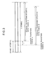
- the Fourier transform timing is offset forward of timing A. If the Fourier transform timing is in the guard interval that precedes timing A, and the Fourier transform can be carried out and the transmit data can be demodulated without inter-symbol interference.
- the Fourier transform is carried out (started) at the timing represented by reference character B, the resulting Fourier transform output can be represented as in the following equation (9) based on the difference ⁇ between the Fourier transform timings A and B, and the carrier frequency spacing f 0 .
- r m , n h m , n ⁇ c m , n ⁇ exp j ⁇ 2 ⁇ ⁇ nf 0 ⁇ ⁇
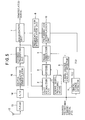
- FIG. 1 is a block diagram showing a receiving apparatus according to a first embodiment of this invention.
- the illustrated receiving apparatus which receives an orthogonal frequency division multiplexed signal in which pilot signals with known values (amplitude and phase) have been inserted, has a known signal providing means 11, a tuner 13 connected to an antenna 12, an A/D converter 14, a digital quadrature demodulator 15, a Fourier transform unit 1, a pilot extraction unit 2, a divider 3, a time-direction interpolation unit 4, a timing change detector 5, a frequency-direction interpolation unit 6, and an equalization unit 7; the outputs of the equalization unit 7 are the demodulated signals of the carriers.
- the pilot extraction unit 2 receives the output from the Fourier transform unit 1 as input, extracts the pilot signals inserted at the transmitter, and outputs the extracted signals.
- the output from the pilot extraction unit 2 is input to the divider 3.
- the timing change detector 5 receives the Fourier transform timing signal FTS as input, detects whether or not the timing of the Fourier transform has changed, generates a signal TCC indicating the detected result, generates a control signal TCD indicating, in the symbols used by the time-direction interpolation unit 4, the locations of the symbol boundaries at which the Fourier transform timing was changed, and outputs these signals TCC and TCD to the time-direction interpolation unit 4.
- the time-direction interpolation unit performs interpolation by using, from among the temporally preceding and following original data, original data generated using a pilot signal included in a symbol that was Fourier-transformed with the same timing as the symbol in which the interpolated data to be generated by interpolation are included, without using original data generated using a pilot signal included in a symbol that was Fourier-transformed with a different timing from the symbol in which the interpolated data to be generated by interpolation are included.
- the time-direction interpolation unit generates the interpolated data by performing interpolation using both the original data most closely preceding and the original data most closely following the interpolated data to be generated by interpolation when these two original data were generated using pilot symbols included in symbols that were Fourier-transformed with mutually identical timings, and generates (the value of) the interpolated data, when one of the original data most closely preceding and the original data most closely following the interpolated data to be generated by interpolation was generated using a pilot signal included in a symbol that was Fourier-transformed with a timing differing from that of the symbol in which the interpolated data to be generated by interpolation are included and another one of the two original data was generated using a pilot signal included in a symbol that was Fourier-transformed with the same timing as that of the symbol in which the interpolated data to be generated by interpolation are included, by selecting as the interpolated data the original data generated using the pilot signal included in the symbol that was Fourier-transformed with the same timing.
- This method of interpolation is referred to in this specification as 'interpolation by selection of neighboring points', or simply 'selection'.
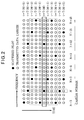
- the pilot signals that provide the original data for interpolation in the time direction are found from the M -6th symbol to the M th symbol, of which the M -6th to M -1st symbols were Fourier-transformed with Fourier transform timing A.
- Interpolation between the pilot signals included in the M -6th and M -2nd symbols (interpolation using these signals as original data) and interpolation between the pilot signals included in the M -5th and M -1st symbols are therefore carried out by conventional linear interpolation.
- Channel characteristic values for the pilot signals included in the M -3rd symbol are output from the divider 3, so interpolation processing is unnecessary; the unaltered outputs of the divider 3 (the original data) are used. Interpolation is not performed between the pilot signals included in the M -4th and Mth symbols because of their differing Fourier transform timings; the output of the divider 3 for the pilot signal included in the M -4th symbol is used as the output of the time-direction interpolation unit 4, because the same Fourier transform timing was used for it as for the M -3rd symbol, which is the symbol for which an estimate of the channel characteristic value is being made (the symbol for which the channel characteristic value is to be calculated).
- the N th carrier in the M th symbol is a scattered pilot s M,N and that its estimated channel characteristic value is h' M,N .
- S M-2,N+6 is a scattered pilot.
- the channel characteristic value of the N +6th carrier is accordingly output from the divider 3 with no need for interpolation, and the unaltered output of the divider 3 is used as the output of the time-direction interpolation unit 4.
- linear interpolation is carried out using the pilot signals included in the M -5th and M -1st symbols as in the following equation (13).
- h ⁇ M - 2 , N + 9 1 / 4 ⁇ h ⁇ M - 5 , N + 9 + 3 / 4 ⁇ h ⁇ M - 1 , N + 9
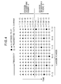
- the pilot signals that provide the original data for interpolation in the time direction are found from the M -4th symbol to the M +2nd symbol, of which the M -4th to M -1st symbols were Fourier-transformed with Fourier transform timing A.
- Channel characteristic values for the pilot signals included in the M -1st symbol are output from the divider 3, so interpolation processing is unnecessary; the unaltered outputs of the divider 3 are used.
- the Nth carrier in the M th symbol is a scattered pilot s M,N and that its estimated channel characteristic value is h' M,N .
- s M-1,N+9 is a scattered pilot.
- the channel characteristic value of the N +9th carrier is accordingly output from the divider 3 with no need for interpolation, and the unaltered output of the divider 3 is used as the output of the time-direction interpolation unit 4.
- the unaltered output of the divider 3 for the N +3rd carrier in the M -3rd symbol is used as the output of the time-direction interpolation unit 4 as in the following equation (17).
- h ⁇ M - 1 , N + 3 h ⁇ M - 3 , N + 3
- the unaltered output of the divider 3 for the N +3rd carrier in the M +1st symbol is used as the output of the time-direction interpolation unit 4 as in the following equation (19).
- h ⁇ M , N + 3 h ⁇ M + 1 , N + 3
- the unaltered output of the divider 3 for the N +6th carrier in the M +2nd symbol is used as the output of the time-direction interpolation unit 4 as in the following equation (20).
- h ⁇ M , N + 6 h ⁇ M + 2 , N + 6
- Values are obtained for one out of every three carriers in the M th symbol by interpolation in the time direction or selection of the outputs of the divider 3 by the same method as above to produce the output of the time-direction interpolation unit 4.
- the N th carrier in the M th symbol is a scattered pilot S M,N and that its estimated channel characteristic value is h' M,N .
- the channel characteristic value of the N +3rd carrier is accordingly output from the divider 3 with no need for interpolation, and the unaltered output of the divider 3 is used as the output of the time-direction interpolation unit 4.
- linear interpolation is carried out using pilot signals included in the M th and M +4th symbols as shown in the following equation (22).
- h ⁇ M + 1 , N 3 / 4 ⁇ h ⁇ M , N + 1 / 4 ⁇ h ⁇ M + 4 , N
- the unaltered output of the divider 3 for the N +9th carrier in the M +3rd symbol is used as the output of the time-direction interpolation unit 4 as in the following equation (24).
- h ⁇ M + 1 , N + 9 h ⁇ M + 3 , N + 9
- the seven consecutive symbols include symbols that have been Fourier-transformed with Fourier transform timing A and symbols that have been Fourier-transformed with Fourier transform timing B. Accordingly, when the pilot signals inserted in these symbols are used for interpolation in the time direction, if time-direction interpolation were to be carried out using pilot signals that had been Fourier-transformed with different Fourier transform timings, incorrect interpolation results would be calculated.
Landscapes
- Engineering & Computer Science (AREA)
- Computer Networks & Wireless Communication (AREA)
- Signal Processing (AREA)
- Power Engineering (AREA)
- Digital Transmission Methods That Use Modulated Carrier Waves (AREA)
- Cable Transmission Systems, Equalization Of Radio And Reduction Of Echo (AREA)
Applications Claiming Priority (2)
| Application Number | Priority Date | Filing Date | Title |
|---|---|---|---|
| JP2005323474A JP3841819B1 (ja) | 2005-11-08 | 2005-11-08 | 直交周波数分割多重信号の受信装置および受信方法 |
| PCT/JP2006/309451 WO2007055042A1 (fr) | 2005-11-08 | 2006-05-11 | Dispositif et procede de reception de signal de multiplexage a division de frequence orthogonale |
Publications (2)
| Publication Number | Publication Date |
|---|---|
| EP1947794A1 true EP1947794A1 (fr) | 2008-07-23 |
| EP1947794A4 EP1947794A4 (fr) | 2013-07-10 |
Family
ID=37477991
Family Applications (1)
| Application Number | Title | Priority Date | Filing Date |
|---|---|---|---|
| EP06746260.6A Withdrawn EP1947794A4 (fr) | 2005-11-08 | 2006-05-11 | Dispositif et procede de reception de signal de multiplexage a division de frequence orthogonale |
Country Status (5)
| Country | Link |
|---|---|
| US (1) | US8077781B2 (fr) |
| EP (1) | EP1947794A4 (fr) |
| JP (1) | JP3841819B1 (fr) |
| CN (1) | CN101243633B (fr) |
| WO (1) | WO2007055042A1 (fr) |
Families Citing this family (13)
| Publication number | Priority date | Publication date | Assignee | Title |
|---|---|---|---|---|
| JP4762186B2 (ja) * | 2007-03-27 | 2011-08-31 | 日本放送協会 | Ofdm受信装置 |
| JP4655241B2 (ja) * | 2008-09-30 | 2011-03-23 | ソニー株式会社 | 受信装置、受信方法、およびプログラム |
| US20110110442A1 (en) * | 2009-11-10 | 2011-05-12 | Industrial Technology Research Institute | Systems, Devices, And Methods For Generating Pilot Patterns For Use In Communications |
| US8675749B2 (en) * | 2010-05-28 | 2014-03-18 | SiTune Corporation | Channel estimation in OFDM transmission system and method |
| JP5577884B2 (ja) * | 2010-06-28 | 2014-08-27 | ソニー株式会社 | 受信装置、及び、受信方法、並びに、受信システム |
| JP5755503B2 (ja) * | 2011-05-30 | 2015-07-29 | 富士通セミコンダクター株式会社 | 受信装置および受信方法 |
| JP5767899B2 (ja) * | 2011-08-23 | 2015-08-26 | 株式会社日立国際電気 | 受信装置 |
| US8718210B2 (en) * | 2011-09-20 | 2014-05-06 | Qualcomm Incorporated | Channel impulse response estimation for wireless receiver |
| US10245420B2 (en) | 2012-06-26 | 2019-04-02 | PicoLife Technologies | Medicament distribution systems and related methods of use |
| GB2513677B (en) * | 2013-10-17 | 2015-09-02 | Imagination Tech Ltd | Channel impulse response |
| JP6286272B2 (ja) * | 2014-04-24 | 2018-02-28 | ソニーセミコンダクタソリューションズ株式会社 | 信号処理装置および信号処理方法、並びにプログラム |
| JP2017046109A (ja) * | 2015-08-25 | 2017-03-02 | 株式会社東芝 | ベースバンド集積回路及び無線通信装置 |
| US20240356781A1 (en) * | 2021-09-30 | 2024-10-24 | Nec Corporation | Wireless communication device, system, method, and non-transitory computer-readable medium |
Family Cites Families (20)
| Publication number | Priority date | Publication date | Assignee | Title |
|---|---|---|---|---|
| CN1980215A (zh) * | 1997-07-01 | 2007-06-13 | 松下电器产业株式会社 | 发送方法、接收方法、发送装置、接收装置 |
| US6618352B1 (en) * | 1998-05-26 | 2003-09-09 | Matsushita Electric Industrial Co., Ltd. | Modulator, demodulator, and transmission system for use in OFDM transmission |
| JP3335933B2 (ja) | 1998-11-30 | 2002-10-21 | 株式会社東芝 | Ofdm復調装置 |
| JP3084368B1 (ja) * | 1999-03-30 | 2000-09-04 | 株式会社次世代デジタルテレビジョン放送システム研究所 | Ofdm用受信装置 |
| JP2001292122A (ja) | 2000-04-07 | 2001-10-19 | Sony Corp | 復調装置及び復調方法 |
| JP4774160B2 (ja) * | 2000-07-13 | 2011-09-14 | パナソニック株式会社 | Ofdm受信装置 |
| TW200401522A (en) * | 2002-05-17 | 2004-01-16 | Matsushita Electric Industrial Co Ltd | Receiving device and receiving method and transmission path characteristic measurement device |
| JP3740468B2 (ja) * | 2003-01-22 | 2006-02-01 | 株式会社東芝 | Ofdm受信装置及びデータ復調方法 |
| US7580466B2 (en) * | 2003-05-12 | 2009-08-25 | Mitsubishi Denki Kabushiki Kaisha | Demodulation device and demodulation method |
| JP4149328B2 (ja) | 2003-07-24 | 2008-09-10 | 日本放送協会 | Ofdm信号のキャリアデータ等化器、およびofdm信号受信装置 |
| US7433433B2 (en) * | 2003-11-13 | 2008-10-07 | Telefonaktiebolaget L M Ericsson (Publ) | Channel estimation by adaptive interpolation |
| JP4314099B2 (ja) * | 2003-11-19 | 2009-08-12 | パナソニック株式会社 | Ofdm受信装置 |
| GB2412551A (en) * | 2004-03-26 | 2005-09-28 | Sony Uk Ltd | Receiver |
| GB2412552A (en) * | 2004-03-26 | 2005-09-28 | Sony Uk Ltd | Receiver |
| JP2006042025A (ja) * | 2004-07-28 | 2006-02-09 | Casio Comput Co Ltd | Ofdm信号復調回路及びofdm信号復調方法 |
| US7474611B2 (en) * | 2005-04-21 | 2009-01-06 | Telefonaktiebolaget L M Ericsson (Publ) | Reduced complexity channel estimation in OFDM systems |
| JP2007202081A (ja) * | 2006-01-30 | 2007-08-09 | Sony Corp | Ofdm復調装置及び方法 |
| JP4664234B2 (ja) * | 2006-05-24 | 2011-04-06 | 富士通セミコンダクター株式会社 | Ofdm受信機 |
| JP4816353B2 (ja) * | 2006-09-12 | 2011-11-16 | ソニー株式会社 | Ofdm受信装置及びofdm信号受信方法 |
| US8098567B2 (en) * | 2007-03-05 | 2012-01-17 | Qualcomm Incorporated | Timing adjustments for channel estimation in a multi carrier system |
-
2005
- 2005-11-08 JP JP2005323474A patent/JP3841819B1/ja not_active Expired - Lifetime
-
2006
- 2006-05-11 EP EP06746260.6A patent/EP1947794A4/fr not_active Withdrawn
- 2006-05-11 US US11/792,345 patent/US8077781B2/en not_active Expired - Fee Related
- 2006-05-11 CN CN2006800301411A patent/CN101243633B/zh not_active Expired - Fee Related
- 2006-05-11 WO PCT/JP2006/309451 patent/WO2007055042A1/fr not_active Ceased
Non-Patent Citations (2)
| Title |
|---|
| See also references of WO2007055042A1 * |
| SPETH M ET AL: "Optimum receiver design for OFDM-based broadband transmission.II. A case study", IEEE TRANSACTIONS ON COMMUNICATIONS, IEEE SERVICE CENTER, PISCATAWAY, NJ. USA, vol. 49, no. 4, 1 April 2001 (2001-04-01), pages 571-578, XP002255287, ISSN: 0090-6778, DOI: 10.1109/26.917759 * |
Also Published As
| Publication number | Publication date |
|---|---|
| EP1947794A4 (fr) | 2013-07-10 |
| CN101243633A (zh) | 2008-08-13 |
| JP3841819B1 (ja) | 2006-11-08 |
| US20080123757A1 (en) | 2008-05-29 |
| JP2007134783A (ja) | 2007-05-31 |
| WO2007055042A1 (fr) | 2007-05-18 |
| US8077781B2 (en) | 2011-12-13 |
| CN101243633B (zh) | 2012-05-23 |
Similar Documents
| Publication | Publication Date | Title |
|---|---|---|
| US8179986B2 (en) | Multicarrier modulation scheme as well as transmission apparatus and reception apparatus using the scheme | |
| EP1580951B1 (fr) | Récepteur | |
| EP0827655B1 (fr) | Procede et appareil permettant d'evaluer simultanement un decalage de frequence et un defaut de synchronisation d'un systeme de modulation a multiples porteuses | |
| US9948436B2 (en) | Receiver and method of receiving | |
| US7133479B2 (en) | Frequency synchronization apparatus and method for OFDM systems | |
| US6449245B1 (en) | Signal receiving apparatus and method and providing medium | |
| US8542774B2 (en) | Receiver and method | |
| EP2264921B1 (fr) | Appareil de réception, procédé de réception, circuit intégré, récepteur de télévision numérique et programme | |
| US20050213679A1 (en) | Receiver | |
| US9847900B2 (en) | Receiver and method of receiving | |
| US9942076B2 (en) | Device and method for detecting and recovering payload data from a signal | |
| EP2204958B1 (fr) | Procédé et système pour la récupération de la temporisation du symbole ofdm | |
| US20090185630A1 (en) | Method and apparatus for estimating the channel impulse response of multi-carrier communicating systems | |
| US8077781B2 (en) | Apparatus and method for receiving an orthogonal frequency division multiplexed signal | |
| US6876672B1 (en) | Method of transmitting data on multiple carriers from a transmitter to a receiver and receiver designed to implement the said method | |
| US10476725B2 (en) | Receiver and method of receiving | |
| JP5175761B2 (ja) | Ofdm受信装置 | |
| JP4285845B2 (ja) | 受信装置 | |
| KR19990079224A (ko) | 직교 주파수 분할 다중 방식에서의 주파수 오프셋 정정장치 | |
| JP4362955B2 (ja) | 復調装置及び復調方法 | |
| JP2002344411A (ja) | Ofdm復調装置及び方法 | |
| JP3907574B2 (ja) | デジタル放送受信機における復調装置 | |
| WO2006018034A1 (fr) | Dispositif de filtre et procede de filtrage de domaine frequentiel | |
| JP2008187652A (ja) | 受信装置及び通信方法 |
Legal Events
| Date | Code | Title | Description |
|---|---|---|---|
| PUAI | Public reference made under article 153(3) epc to a published international application that has entered the european phase |
Free format text: ORIGINAL CODE: 0009012 |
|
| 17P | Request for examination filed |
Effective date: 20070531 |
|
| AK | Designated contracting states |
Kind code of ref document: A1 Designated state(s): DE GB IT SE |
|
| DAX | Request for extension of the european patent (deleted) | ||
| RBV | Designated contracting states (corrected) |
Designated state(s): DE GB IT SE |
|
| A4 | Supplementary search report drawn up and despatched |
Effective date: 20130611 |
|
| RIC1 | Information provided on ipc code assigned before grant |
Ipc: H04L 27/26 20060101ALI20130605BHEP Ipc: H04J 11/00 20060101AFI20130605BHEP Ipc: H04L 25/02 20060101ALI20130605BHEP |
|
| 17Q | First examination report despatched |
Effective date: 20140304 |
|
| GRAP | Despatch of communication of intention to grant a patent |
Free format text: ORIGINAL CODE: EPIDOSNIGR1 |
|
| STAA | Information on the status of an ep patent application or granted ep patent |
Free format text: STATUS: GRANT OF PATENT IS INTENDED |
|
| INTG | Intention to grant announced |
Effective date: 20170529 |
|
| GRAJ | Information related to disapproval of communication of intention to grant by the applicant or resumption of examination proceedings by the epo deleted |
Free format text: ORIGINAL CODE: EPIDOSDIGR1 |
|
| STAA | Information on the status of an ep patent application or granted ep patent |
Free format text: STATUS: EXAMINATION IS IN PROGRESS |
|
| INTC | Intention to grant announced (deleted) | ||
| GRAP | Despatch of communication of intention to grant a patent |
Free format text: ORIGINAL CODE: EPIDOSNIGR1 |
|
| STAA | Information on the status of an ep patent application or granted ep patent |
Free format text: STATUS: GRANT OF PATENT IS INTENDED |
|
| INTG | Intention to grant announced |
Effective date: 20180508 |
|
| RAP1 | Party data changed (applicant data changed or rights of an application transferred) |
Owner name: MITSUBISHI ELECTRIC CORPORATION |
|
| STAA | Information on the status of an ep patent application or granted ep patent |
Free format text: STATUS: THE APPLICATION IS DEEMED TO BE WITHDRAWN |
|
| 18D | Application deemed to be withdrawn |
Effective date: 20180919 |