EP1948092B1 - Implantat, insbesondere teilimplantat für den ulnakopf - Google Patents
Implantat, insbesondere teilimplantat für den ulnakopf Download PDFInfo
- Publication number
- EP1948092B1 EP1948092B1 EP06820882.6A EP06820882A EP1948092B1 EP 1948092 B1 EP1948092 B1 EP 1948092B1 EP 06820882 A EP06820882 A EP 06820882A EP 1948092 B1 EP1948092 B1 EP 1948092B1
- Authority
- EP
- European Patent Office
- Prior art keywords
- head
- implant
- ulna
- implant according
- transverse
- Prior art date
- Legal status (The legal status is an assumption and is not a legal conclusion. Google has not performed a legal analysis and makes no representation as to the accuracy of the status listed.)
- Active
Links
Images


Classifications
-
- A—HUMAN NECESSITIES
- A61—MEDICAL OR VETERINARY SCIENCE; HYGIENE
- A61F—FILTERS IMPLANTABLE INTO BLOOD VESSELS; PROSTHESES; DEVICES PROVIDING PATENCY TO, OR PREVENTING COLLAPSING OF, TUBULAR STRUCTURES OF THE BODY, e.g. STENTS; ORTHOPAEDIC, NURSING OR CONTRACEPTIVE DEVICES; FOMENTATION; TREATMENT OR PROTECTION OF EYES OR EARS; BANDAGES, DRESSINGS OR ABSORBENT PADS; FIRST-AID KITS
- A61F2/00—Filters implantable into blood vessels; Prostheses, i.e. artificial substitutes or replacements for parts of the body; Appliances for connecting them with the body; Devices providing patency to, or preventing collapsing of, tubular structures of the body, e.g. stents
- A61F2/02—Prostheses implantable into the body
- A61F2/30—Joints
- A61F2/42—Joints for wrists or ankles; for hands, e.g. fingers; for feet, e.g. toes
- A61F2/4261—Joints for wrists or ankles; for hands, e.g. fingers; for feet, e.g. toes for wrists
-
- A—HUMAN NECESSITIES
- A61—MEDICAL OR VETERINARY SCIENCE; HYGIENE
- A61F—FILTERS IMPLANTABLE INTO BLOOD VESSELS; PROSTHESES; DEVICES PROVIDING PATENCY TO, OR PREVENTING COLLAPSING OF, TUBULAR STRUCTURES OF THE BODY, e.g. STENTS; ORTHOPAEDIC, NURSING OR CONTRACEPTIVE DEVICES; FOMENTATION; TREATMENT OR PROTECTION OF EYES OR EARS; BANDAGES, DRESSINGS OR ABSORBENT PADS; FIRST-AID KITS
- A61F2/00—Filters implantable into blood vessels; Prostheses, i.e. artificial substitutes or replacements for parts of the body; Appliances for connecting them with the body; Devices providing patency to, or preventing collapsing of, tubular structures of the body, e.g. stents
- A61F2/02—Prostheses implantable into the body
- A61F2/30—Joints
- A61F2002/30001—Additional features of subject-matter classified in A61F2/28, A61F2/30 and subgroups thereof
- A61F2002/30316—The prosthesis having different structural features at different locations within the same prosthesis; Connections between prosthetic parts; Special structural features of bone or joint prostheses not otherwise provided for
- A61F2002/30329—Connections or couplings between prosthetic parts, e.g. between modular parts; Connecting elements
- A61F2002/30331—Connections or couplings between prosthetic parts, e.g. between modular parts; Connecting elements made by longitudinally pushing a protrusion into a complementarily-shaped recess, e.g. held by friction fit
-
- A—HUMAN NECESSITIES
- A61—MEDICAL OR VETERINARY SCIENCE; HYGIENE
- A61F—FILTERS IMPLANTABLE INTO BLOOD VESSELS; PROSTHESES; DEVICES PROVIDING PATENCY TO, OR PREVENTING COLLAPSING OF, TUBULAR STRUCTURES OF THE BODY, e.g. STENTS; ORTHOPAEDIC, NURSING OR CONTRACEPTIVE DEVICES; FOMENTATION; TREATMENT OR PROTECTION OF EYES OR EARS; BANDAGES, DRESSINGS OR ABSORBENT PADS; FIRST-AID KITS
- A61F2/00—Filters implantable into blood vessels; Prostheses, i.e. artificial substitutes or replacements for parts of the body; Appliances for connecting them with the body; Devices providing patency to, or preventing collapsing of, tubular structures of the body, e.g. stents
- A61F2/02—Prostheses implantable into the body
- A61F2/30—Joints
- A61F2002/30001—Additional features of subject-matter classified in A61F2/28, A61F2/30 and subgroups thereof
- A61F2002/30316—The prosthesis having different structural features at different locations within the same prosthesis; Connections between prosthetic parts; Special structural features of bone or joint prostheses not otherwise provided for
- A61F2002/30329—Connections or couplings between prosthetic parts, e.g. between modular parts; Connecting elements
- A61F2002/30331—Connections or couplings between prosthetic parts, e.g. between modular parts; Connecting elements made by longitudinally pushing a protrusion into a complementarily-shaped recess, e.g. held by friction fit
- A61F2002/30362—Connections or couplings between prosthetic parts, e.g. between modular parts; Connecting elements made by longitudinally pushing a protrusion into a complementarily-shaped recess, e.g. held by friction fit with possibility of relative movement between the protrusion and the recess
- A61F2002/30369—Limited lateral translation of the protrusion within a larger recess
-
- A—HUMAN NECESSITIES
- A61—MEDICAL OR VETERINARY SCIENCE; HYGIENE
- A61F—FILTERS IMPLANTABLE INTO BLOOD VESSELS; PROSTHESES; DEVICES PROVIDING PATENCY TO, OR PREVENTING COLLAPSING OF, TUBULAR STRUCTURES OF THE BODY, e.g. STENTS; ORTHOPAEDIC, NURSING OR CONTRACEPTIVE DEVICES; FOMENTATION; TREATMENT OR PROTECTION OF EYES OR EARS; BANDAGES, DRESSINGS OR ABSORBENT PADS; FIRST-AID KITS
- A61F2/00—Filters implantable into blood vessels; Prostheses, i.e. artificial substitutes or replacements for parts of the body; Appliances for connecting them with the body; Devices providing patency to, or preventing collapsing of, tubular structures of the body, e.g. stents
- A61F2/02—Prostheses implantable into the body
- A61F2/30—Joints
- A61F2002/30001—Additional features of subject-matter classified in A61F2/28, A61F2/30 and subgroups thereof
- A61F2002/30316—The prosthesis having different structural features at different locations within the same prosthesis; Connections between prosthetic parts; Special structural features of bone or joint prostheses not otherwise provided for
- A61F2002/30535—Special structural features of bone or joint prostheses not otherwise provided for
- A61F2002/30563—Special structural features of bone or joint prostheses not otherwise provided for having elastic means or damping means, different from springs, e.g. including an elastomeric core or shock absorbers
-
- A—HUMAN NECESSITIES
- A61—MEDICAL OR VETERINARY SCIENCE; HYGIENE
- A61F—FILTERS IMPLANTABLE INTO BLOOD VESSELS; PROSTHESES; DEVICES PROVIDING PATENCY TO, OR PREVENTING COLLAPSING OF, TUBULAR STRUCTURES OF THE BODY, e.g. STENTS; ORTHOPAEDIC, NURSING OR CONTRACEPTIVE DEVICES; FOMENTATION; TREATMENT OR PROTECTION OF EYES OR EARS; BANDAGES, DRESSINGS OR ABSORBENT PADS; FIRST-AID KITS
- A61F2/00—Filters implantable into blood vessels; Prostheses, i.e. artificial substitutes or replacements for parts of the body; Appliances for connecting them with the body; Devices providing patency to, or preventing collapsing of, tubular structures of the body, e.g. stents
- A61F2/02—Prostheses implantable into the body
- A61F2/30—Joints
- A61F2/42—Joints for wrists or ankles; for hands, e.g. fingers; for feet, e.g. toes
- A61F2/4261—Joints for wrists or ankles; for hands, e.g. fingers; for feet, e.g. toes for wrists
- A61F2002/4269—Joints for wrists or ankles; for hands, e.g. fingers; for feet, e.g. toes for wrists for distal radio-ulnar joints, i.e. DRU joints
-
- A—HUMAN NECESSITIES
- A61—MEDICAL OR VETERINARY SCIENCE; HYGIENE
- A61F—FILTERS IMPLANTABLE INTO BLOOD VESSELS; PROSTHESES; DEVICES PROVIDING PATENCY TO, OR PREVENTING COLLAPSING OF, TUBULAR STRUCTURES OF THE BODY, e.g. STENTS; ORTHOPAEDIC, NURSING OR CONTRACEPTIVE DEVICES; FOMENTATION; TREATMENT OR PROTECTION OF EYES OR EARS; BANDAGES, DRESSINGS OR ABSORBENT PADS; FIRST-AID KITS
- A61F2220/00—Fixations or connections for prostheses classified in groups A61F2/00 - A61F2/26 or A61F2/82 or A61F9/00 or A61F11/00 or subgroups thereof
- A61F2220/0025—Connections or couplings between prosthetic parts, e.g. between modular parts; Connecting elements
- A61F2220/0033—Connections or couplings between prosthetic parts, e.g. between modular parts; Connecting elements made by longitudinally pushing a protrusion into a complementary-shaped recess, e.g. held by friction fit
-
- A—HUMAN NECESSITIES
- A61—MEDICAL OR VETERINARY SCIENCE; HYGIENE
- A61F—FILTERS IMPLANTABLE INTO BLOOD VESSELS; PROSTHESES; DEVICES PROVIDING PATENCY TO, OR PREVENTING COLLAPSING OF, TUBULAR STRUCTURES OF THE BODY, e.g. STENTS; ORTHOPAEDIC, NURSING OR CONTRACEPTIVE DEVICES; FOMENTATION; TREATMENT OR PROTECTION OF EYES OR EARS; BANDAGES, DRESSINGS OR ABSORBENT PADS; FIRST-AID KITS
- A61F2310/00—Prostheses classified in A61F2/28 or A61F2/30 - A61F2/44 being constructed from or coated with a particular material
- A61F2310/00005—The prosthesis being constructed from a particular material
- A61F2310/00011—Metals or alloys
- A61F2310/00023—Titanium or titanium-based alloys, e.g. Ti-Ni alloys
-
- A—HUMAN NECESSITIES
- A61—MEDICAL OR VETERINARY SCIENCE; HYGIENE
- A61F—FILTERS IMPLANTABLE INTO BLOOD VESSELS; PROSTHESES; DEVICES PROVIDING PATENCY TO, OR PREVENTING COLLAPSING OF, TUBULAR STRUCTURES OF THE BODY, e.g. STENTS; ORTHOPAEDIC, NURSING OR CONTRACEPTIVE DEVICES; FOMENTATION; TREATMENT OR PROTECTION OF EYES OR EARS; BANDAGES, DRESSINGS OR ABSORBENT PADS; FIRST-AID KITS
- A61F2310/00—Prostheses classified in A61F2/28 or A61F2/30 - A61F2/44 being constructed from or coated with a particular material
- A61F2310/00005—The prosthesis being constructed from a particular material
- A61F2310/00161—Carbon; Graphite
- A61F2310/00173—Graphite
-
- A—HUMAN NECESSITIES
- A61—MEDICAL OR VETERINARY SCIENCE; HYGIENE
- A61F—FILTERS IMPLANTABLE INTO BLOOD VESSELS; PROSTHESES; DEVICES PROVIDING PATENCY TO, OR PREVENTING COLLAPSING OF, TUBULAR STRUCTURES OF THE BODY, e.g. STENTS; ORTHOPAEDIC, NURSING OR CONTRACEPTIVE DEVICES; FOMENTATION; TREATMENT OR PROTECTION OF EYES OR EARS; BANDAGES, DRESSINGS OR ABSORBENT PADS; FIRST-AID KITS
- A61F2310/00—Prostheses classified in A61F2/28 or A61F2/30 - A61F2/44 being constructed from or coated with a particular material
- A61F2310/00389—The prosthesis being coated or covered with a particular material
- A61F2310/00574—Coating or prosthesis-covering structure made of carbon, e.g. of pyrocarbon
- A61F2310/0058—Coating made of diamond or of diamond-like carbon DLC
Definitions
- a partial implant of the head of the ulna is described in the article entitled "Kinematics of ulnar head arthroplasty" by KD Gordon et al. published in The Journal of Hand Surgery, vol. 28B No. 6, December 2003 . It comprises a hemispherical head intended to replace the articular part of the head of the ulna, that is to say the lateral part of the distal end of the ulna articulated at the head of the radius.
- the hemispherical head is fitted on the end of a rod and rigidly fixed thereto by means of a screw, the rod being in turn intended to be fixed rigidly inside a hole formed in the ulna to hold the implant in place.
- such a partial implant can preserve the triangular ligament, which connects the head of the ulna and the radius, the ulnocarpus ligament, which connects the ulna and carp, and maintain stretched the interosseous membrane connecting the ulna and the radius.
- the stability of such a partial implant is therefore much greater than that of a total implant.
- the transverse loads received by the head of the implant are transmitted to the rod. This results in the remaining portion of the ulna head, as well as the surrounding ligaments, no longer receiving the charges they initially received. No longer under pressure, the remaining part of the head of the ulna is doomed to gradually decalcify and the surrounding ligaments to lose their vigor.
- WO-A-91/16017 discloses a total implant of the head of the ulna, comprising a head, fixedly attached to the radius and connected to a rod which is fixed rigidly to the ulna whose head has been previously resected in screen.
- the head of this implant is designed mobile in translation relative to the rod in a direction transverse to the bones of the radius and the ulna, in other words in a direction parallel to the aforementioned transverse loads.
- This internal translational mobility of the implant allows the radius to be rotated around the ulna during a rotation of the patient's wrist.
- this solution does not remedy the drawback presented above, relating to the devitalization of the region of the end of the ulna.
- an implant is proposed, in particular a partial implant of the head of the ulna, as defined in claim 1.
- the head of the implant can come to bear against the remaining part of the bone on which it is mounted and / or against the surrounding ligaments during movements of the patient and can thus their transmit the transverse loads it receives.
- said head is made of pyrocarbon and its outer surface is polished.
- the holding element is advantageously a rod whose axis is transverse to the aforementioned direction and which is designed to be held simply by elastic deformation in a hole previously formed in said bone.
- This rod is for example integral with a pin engaged in a bore of the head, the mobility in transverse translation of the head relative to the rod being obtained by a clearance between the pin and the head.
- the respective sections Both the nipple and the bore are circular and the nipple section is smaller in diameter than the section of the bore.
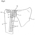
- a partial implant of the head of the ulna comprises a head 1 connected to a rod 2 by means of a pin 3 projecting from a plate 4 located at one end of the rod 2.
- the axis of the pin 3 is parallel, but not confused, with the axis of the rod 2.
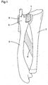
- the head 1 is intended to be placed in a space obtained by removing the articular part of the head of the ulna, as shown in FIGS.
- the rod 2, the pin 3 and the plate 4 preferably form a single piece, made of metal, for example titanium.
- the implant according to the invention does not need to be securely attached to the bone on which it is mounted, in this case the ulna.
- the rod 2 is not intended to withstand high stresses but simply to position the implant to prevent dislocation during pronation and supination movements.
- This rod 2 may thus consist of elastic arms 11, four in number in the illustrated example, deforming during their insertion into the ulna to hold the implant in place only by their elastic deformation.
- the stability of the implant according to the invention is ensured above all by the remaining part 6 of the head of the ulna and by the surrounding ligaments.
- the triangular ligament 10 holds the implant in the axial direction (cf. figure 2 ).
- the head 1 of the implant according to the invention is made of pyrocarbon and its outer surface is polished.
- the pyrocarbon has a modulus of elasticity (Young's modulus) close to that of the bone, which enables it, especially if its surface is polished, to rub against the bone without causing wear and tear. neither of itself.
- the head 1 consists of a graphite core covered with a pyrocarbon layer, the graphite-pyrocarbon assembly having a modulus of elasticity (Young's modulus) close to that of the bone.
- the head 1 is solid pyrocarbon, that is to say is devoid of graphite core.
- the head 1 substantially has the shape of a hemisphere truncated by two planes parallel to each other and perpendicular to the planar face of the hemisphere and to the axis of the rod 2.
- the flat face 1a and the hemispherical face 1b of the periphery of the head 1 are intended to be placed facing, respectively, the remaining portion 6 of the head of the ulna and the head of the radius 7.
- the head 1 does not need to have a form precisely respecting the anatomy of the head of the ulna, the role of this head 1 being, as will be seen below, to serve as an interposition piece between the head of the radius and the remaining portion 6 of the head of the ulna.
- a bore 12 is formed in the head 1 to receive the pin 3 and thus connect the head 1 to the rod 2.
- this bore 12 has a larger section than the pin 3 so as to create a clearance 13 between the head 1 and the pin 3 making the head 1 movable transversely to the axis of the rod 2, as shown by the arrows on the Figures 3 and 4 .
- the notion of transverse mobility means mobility in translation in a plane intersecting the axis of the rod 2 and parallel to the transverse loads applied by the radial head when the implant is in contact. place in the patient. In the illustrated example, where the rod 2 and the pin 3 are parallel, the aforementioned plane is substantially perpendicular to the respective axes of the rod 2 and the ulna.
- the clearance 13 between the head 1 and the pin 3 is about 1 mm.
- the respective sections of the bore 12 and the stud 3 are both circular, but of different diameters, thus allowing the head 1 to move in all directions of a plane transverse to the rod 2.
- the section of the bore 12 could have another shape, for example an oblong shape, to favor a particular direction of transverse displacement of the head 1.
- the function of the pin 3 is simply to limit the transverse displacements of the head 1. Note that the head 1 does not need to be made integral axially with the rod 2. Once the implant is in place, indeed , the head 1 is retained axially by the triangular ligament 10. For cases where the triangular ligament 10 is damaged, one could nevertheless provide a variant in which the head 1 would be locked axially relative to the rod 2, for example by a bulge provided on the perimeter of the stud 3 or by a plate attached to the end of the stud 3 opposite the plate 4.
- the head 1 of the implant according to the invention is intended to be interposed between the articular part of the head of the radius 7 and the remaining part 6 of the head of the ulna 5, the hemispherical surface 1b of the head 1 serving as a hinge surface with the head of the radius 7. Because the portion 6 of the head of the ulna 5 is retained, the triangular ligament 10 which connects the ulna and the radius and the ligament ulnocarpien (not visible on the drawings) and the sheath of the posterior ulnar tendon 9 are preserved and the interosseous membrane 8 remains tight. All these ligaments 8-10 can thus continue to fulfill their function.
- the triangular ligament 10 is distended.
- a size in the transverse plane slightly greater than the size of the head portion of the ulna it replaces is chosen.
- the presence of the head 1 keeps the heads of the ulna and the radius slightly apart from each other with respect to their anatomical position, as shown by the double arrow on the figure 2 , which retains the triangular ligament 10.
- the transverse mobility of the head 1 relative to the holding rod 2 has several advantages. First, it reduces the loads that the rod 2 receives when the head of the ulna is subjected to transverse stresses, in particular during rotational movements of the forearm (pronation, supination), and increases those received by the Remaining 6 of the head of the ulna and the surrounding ligaments. Indeed, instead of transmitting the bulk of the transverse stresses received at the rod 2, the head 1, moving transversely, comes to bear against the remaining portion 6 of the head of the ulna and / or against the surrounding ligaments, which thus receive stresses close to those which they received before the removal of the articular part of the head of the ulna. The original stability of the head of the ulna is respected. The remaining portion 6 of the ulna head, as it continues to be constrained, retains its substance. As for the surrounding ligaments, put in tension by the transverse movements of the head 1, they also remain active.
Landscapes
- Health & Medical Sciences (AREA)
- Orthopedic Medicine & Surgery (AREA)
- Cardiology (AREA)
- Oral & Maxillofacial Surgery (AREA)
- Transplantation (AREA)
- Engineering & Computer Science (AREA)
- Biomedical Technology (AREA)
- Heart & Thoracic Surgery (AREA)
- Vascular Medicine (AREA)
- Life Sciences & Earth Sciences (AREA)
- Animal Behavior & Ethology (AREA)
- General Health & Medical Sciences (AREA)
- Public Health (AREA)
- Veterinary Medicine (AREA)
- Prostheses (AREA)
Claims (12)
- Implantat, umfassend einen Kopf (1) zum Ersetzen mindestens eines seitlichen Gelenkteils eines querbelasteten Knochens und ein Halteelement (2), das mit dem Kopf (1) verbunden ist und zur Befestigung an dem Knochen bestimmt ist, wobei der Kopf (1) bezogen auf das Halteelement (2) in mindestens eine Richtung, welche parallel zu der Querbelastung verläuft, translatorisch beweglich ist, wobei das Implantat im Patienten angebracht ist,
dadurch gekennzeichnet, dass der Kopf (1) an seinem Außenumfang mit zwei gegenüberliegenden Seiten (1a, 1b) versehen ist, nämlich einer Gelenkseite, gegen welche die Querbelastung in vorgenannter Richtung wirkt, und einer Stützseite zur Anlage gegen den übrigen Teil des Knochens und/oder gegen die umliegenden Bänder. - Implantat nach Anspruch 1, dadurch gekennzeichnet, dass der Kopf (1) aus Pyrokohlenstoff ist.
- Implantat nach Anspruch 2, dadurch gekennzeichnet, dass die Außenfläche des Kopfes (1) poliert ist.
- Implantat nach einem der Ansprüche 1 bis 3, dadurch gekennzeichnet, dass das Halteelement (2) eine Stange ist.
- Implantat nach Anspruch 4, dadurch gekennzeichnet, dass die Richtung, in welche der Kopf (1) translatorisch bewegbar ist, bezogen auf die Achse der Stange (2) quer verläuft.
- Implantat nach Anspruch 5, dadurch gekennzeichnet, dass die Stange (2) fest mit einem in einer Bohrung (12) des Kopfes (1) angebrachten Bolzen (3) verbunden ist, wobei die translatorische Querbeweglichkeit des Kopfes (1) bezogen auf die Stange (2) durch ein Spiel (13) zwischen dem Bolzen (3) und dem Kopf (1) erreichbar ist.
- Implantat nach Anspruch 6, dadurch gekennzeichnet, dass die jeweiligen Abschnitte des Bolzens (3) und der Bohrung (12) beide kreisförmig sind und der Abschnitt des Bolzens (3) einen kleineren Durchmesser als der Abschnitt der Bohrung (12) aufweist.
- Implantat nach einem der Ansprüche 4 bis 7, dadurch gekennzeichnet, dass die Stange (2) derart konzipiert ist, dass sie in einem Loch des Knochens lediglich durch elastische Verformung haltbar ist.
- Implantat nach einem der Ansprüche 1 bis 8, dadurch gekennzeichnet, dass das Implantat aus einem Teilimplantat besteht.
- Implantat nach einem der Ansprüche 1 bis 8, dadurch gekennzeichnet, dass das Implantat aus einem Implantat des Ulnakopfes besteht und dass die Gelenkseite (1b) des Kopfes (1) für eine gelenkige Verbindung mit dem Speichenkopf (7) vorgesehen ist.
- Implantat nach Anspruch 10, dadurch gekennzeichnet, dass das Implantat aus einem Teilimplantat des Ulnakopfes besteht und dass die Stützseite (1a) für die Abstützung gegen den übrigen Teil (6) des Ulnakopfes (5) vorgesehen ist.
- Implantat nach einem der vorangehenden Ansprüche, dadurch gekennzeichnet, dass die Gelenkseite (1b) des Kopfes (1) eine Halbkugel ist und dass die Stützseite (1a) eben ist.
Applications Claiming Priority (2)
| Application Number | Priority Date | Filing Date | Title |
|---|---|---|---|
| FR0511671A FR2893247B1 (fr) | 2005-11-17 | 2005-11-17 | Implant, notamment implant partiel de la tete du cubitus |
| PCT/IB2006/003190 WO2007057741A2 (fr) | 2005-11-17 | 2006-11-14 | Implant, notamment implant partiel de la tête du cubitus |
Publications (2)
| Publication Number | Publication Date |
|---|---|
| EP1948092A2 EP1948092A2 (de) | 2008-07-30 |
| EP1948092B1 true EP1948092B1 (de) | 2016-08-17 |
Family
ID=37114491
Family Applications (1)
| Application Number | Title | Priority Date | Filing Date |
|---|---|---|---|
| EP06820882.6A Active EP1948092B1 (de) | 2005-11-17 | 2006-11-14 | Implantat, insbesondere teilimplantat für den ulnakopf |
Country Status (4)
| Country | Link |
|---|---|
| US (1) | US8088168B2 (de) |
| EP (1) | EP1948092B1 (de) |
| FR (1) | FR2893247B1 (de) |
| WO (1) | WO2007057741A2 (de) |
Families Citing this family (22)
| Publication number | Priority date | Publication date | Assignee | Title |
|---|---|---|---|---|
| US8398717B2 (en) * | 2008-11-10 | 2013-03-19 | Acumed Llc | Partial or complete prosthetic replacement arthroplasty of the distal radioulnar joint |
| US20100131069A1 (en) * | 2007-08-01 | 2010-05-27 | Jeffrey Halbrecht | Method and system for patella tendon realignment |
| WO2009018365A1 (en) * | 2007-08-01 | 2009-02-05 | Jeffrey Halbrecht | Method and system for patella tendon realignment |
| DE602007007095D1 (de) * | 2007-11-07 | 2010-07-22 | Gs Dev Ab | Künstliches Gelenk |
| US8052755B2 (en) * | 2008-05-09 | 2011-11-08 | Remi Sciences, Inc. | Ulnar head prosthesis system |
| FR2940760B1 (fr) | 2009-01-08 | 2010-12-31 | Memometal Technologies | Implant orthopedique pour arthroplastie digitale |
| WO2010151589A1 (en) * | 2009-06-23 | 2010-12-29 | Replication Medical, Inc. | Trapezium prosthesis |
| US9668868B2 (en) | 2009-08-27 | 2017-06-06 | Cotera, Inc. | Apparatus and methods for treatment of patellofemoral conditions |
| US9278004B2 (en) | 2009-08-27 | 2016-03-08 | Cotera, Inc. | Method and apparatus for altering biomechanics of the articular joints |
| US10349980B2 (en) | 2009-08-27 | 2019-07-16 | The Foundry, Llc | Method and apparatus for altering biomechanics of the shoulder |
| CA2771332C (en) * | 2009-08-27 | 2020-11-10 | Cotera, Inc. | Method and apparatus for force redistribution in articular joints |
| US9861408B2 (en) | 2009-08-27 | 2018-01-09 | The Foundry, Llc | Method and apparatus for treating canine cruciate ligament disease |
| FR2984781B1 (fr) * | 2011-12-22 | 2014-01-24 | Commissariat Energie Atomique | Procede d'assemblage par brasage d'un substrat comprenant du pyrocarbone avec des pieces comprenant du pyrocarbone. |
| US9468466B1 (en) | 2012-08-24 | 2016-10-18 | Cotera, Inc. | Method and apparatus for altering biomechanics of the spine |
| US9480486B2 (en) * | 2013-03-15 | 2016-11-01 | Albert H. Burstein | Joint replacement spacers |
| US10575968B2 (en) | 2014-05-16 | 2020-03-03 | Howmedica Osteonics Corp. | Guides for fracture system |
| US9681960B2 (en) | 2014-05-16 | 2017-06-20 | Howmedica Osteonics Corp. | Guides for fracture system |
| FR3021524A1 (fr) | 2014-06-02 | 2015-12-04 | Small Bone Innovations Internat | Tige d'ancrage metacarpien, notamment pour une prothese trapezo-metacarpienne |
| WO2016178946A1 (en) * | 2015-05-01 | 2016-11-10 | Mayo Foundation For Medical Education And Research | Distal radioulnar joint prosthesis and method of use |
| EP4084711A4 (de) | 2020-01-02 | 2024-01-03 | ZKR Orthopedics, Inc. | Implantat zur neuausrichtung der patellasehne mit veränderbarer form |
| WO2021231253A1 (en) | 2020-05-11 | 2021-11-18 | Zkr Orthopedics, Inc. | Adjustable patellar tendon realignment implant |
| AU2024334108A1 (en) | 2023-08-29 | 2026-02-26 | Zkr Orthopedics, Inc. | Multiplanar tendon realignment implants and related systems and methods |
Family Cites Families (57)
| Publication number | Priority date | Publication date | Assignee | Title |
|---|---|---|---|---|
| US3526005A (en) * | 1967-06-29 | 1970-09-01 | Gulf General Atomic Inc | Method of preparing an intravascular defect by implanting a pyrolytic carbon coated prosthesis |
| US3707006A (en) * | 1970-08-26 | 1972-12-26 | Gulf Oil Corp | Orthopedic device for repair or replacement of bone |
| US3745590A (en) * | 1971-06-25 | 1973-07-17 | Cutter Lab | Articulating prosthesis with ligamentous attachment |
| US4005163A (en) * | 1974-08-23 | 1977-01-25 | General Atomic Company | Carbon bearings via vapor deposition |
| US3924276A (en) * | 1975-02-18 | 1975-12-09 | Richard E Eaton | Surgically implantable trapezium prosthesis and method of reconstructing the thumb carpometacarpal joint |
| US4166292A (en) * | 1977-09-08 | 1979-09-04 | Carbomedics, Inc. | Stress reinforced artificial joint prostheses |
| US4164793A (en) * | 1978-04-26 | 1979-08-21 | Swanson Alfred B | Lunate implant |
| US4198712A (en) * | 1978-10-13 | 1980-04-22 | Swanson Alfred B | Scaphoid implant |
| US4259752A (en) * | 1980-01-04 | 1981-04-07 | Julio Taleisnik | Endoprosthetic wrist joint |
| US4645505A (en) * | 1985-03-07 | 1987-02-24 | Swanson Alfred B | Wrist implant |
| US4784661A (en) * | 1985-11-22 | 1988-11-15 | Robert Beckenbaugh | Total wrist prosthesis |
| US4936860A (en) * | 1988-09-23 | 1990-06-26 | Swanson Alfred B | Metal scaphoid implant |
| US4955915A (en) * | 1989-06-02 | 1990-09-11 | Swanson Alfred B | Lunate implant and method of stabilizing same |
| SE9001521D0 (sv) * | 1990-04-26 | 1990-04-26 | Per Ingvar Branemark | System och metod foer rekonstruktion av leder, i synnerhet handleder |
| SE9001520D0 (sv) * | 1990-04-26 | 1990-04-26 | Braanemark Ingvar | System foer rekonstruktion av den distala, radio-ulnara leden (dru-leden) i handleder |
| FR2680967B1 (fr) | 1991-09-06 | 1993-10-29 | Commissariat A Energie Atomique | Prothese articulaire digitale pour articulations metacarpophalangiennes et interphalangiennes. |
| FR2681240A1 (fr) * | 1991-09-12 | 1993-03-19 | Tornier Sa | Prothese totale de poignet. |
| US5326364A (en) * | 1992-12-16 | 1994-07-05 | Wright Medical Technology, Inc. | Trapezial implant |
| US5702472A (en) * | 1996-12-26 | 1997-12-30 | Huebner; Randall J. | Phalangeal finger joint prosthesis and method |
| US5735905A (en) * | 1995-04-27 | 1998-04-07 | Southwest Research Institute | Shock absorbing element for a load bearing prosthesis |
| ATE204449T1 (de) * | 1995-06-21 | 2001-09-15 | Sulzer Orthopaedie Ag | Künstliches handgelenk |
| US5645605A (en) * | 1995-09-18 | 1997-07-08 | Ascension Orthopedics, Inc. | Implant device to replace the carpometacarpal joint of the human thumb |
| US5702469A (en) * | 1996-01-18 | 1997-12-30 | Kinetikos Medical, Inc. | Thumb joint prosthesis and related method of implantation |
| FR2743717B1 (fr) * | 1996-01-23 | 1998-04-30 | Maksene Philippe | Prothese d'articulation phalangienne |
| US5780119A (en) * | 1996-03-20 | 1998-07-14 | Southwest Research Institute | Treatments to reduce friction and wear on metal alloy components |
| US5743918A (en) * | 1996-05-13 | 1998-04-28 | Wright Medical Technology, Inc. | Instrumentation for and method for implanting a spherical prosthesis |
| DE19620525A1 (de) * | 1996-05-22 | 1997-11-27 | Gmt Medizinische Technik Gmbh | Ellbogengelenk-Endoprothese |
| US5782927A (en) * | 1996-11-06 | 1998-07-21 | Ascension Orthopedics, Inc. | Metacarpal-phalangeal joint replacement |
| US5938699A (en) * | 1997-04-18 | 1999-08-17 | Campbell; G. Stewart | Distal radial ulnar joint reconstruction system |
| AU7635198A (en) * | 1997-06-18 | 1999-01-04 | Andre Bahler | Endoprosthesis for a joint, in particular a finger, toe or wrist joint |
| DE29721522U1 (de) | 1997-12-05 | 1998-02-05 | Moje, Hans-Jürgen, 07607 Eisenberg | Nichtgeführte Endoprothese für Fingergrundgelenk |
| DE29722973U1 (de) * | 1997-12-30 | 1999-03-25 | Thabe, Heiner, Dr.med., 55543 Bad Kreuznach | Handgelenkprothese |
| US5951604A (en) * | 1997-12-31 | 1999-09-14 | Avanta Orthopedics, Inc. | Distal radioulnar joint prosthesis |
| US6454808B1 (en) * | 1998-01-28 | 2002-09-24 | M-E-System Inc. | Finger joint prosthesis |
| US6217616B1 (en) * | 1998-09-09 | 2001-04-17 | Ascension Orthopedics, Inc. | Elbow prosthesis |
| DE19925529A1 (de) | 1999-06-04 | 2000-12-07 | Moje Hans Juergen | Nichtgeführte Endoprothese für Fingergelenke |
| FR2800269B1 (fr) * | 1999-11-02 | 2003-08-08 | Jean Claude Bouvet | Tige femorale pour prothese de hanche |
| US6296666B1 (en) * | 2000-03-13 | 2001-10-02 | Encore Medical Corporation | Mobile bearing knee with center post |
| DE50103437D1 (de) * | 2000-03-21 | 2004-10-07 | Ct Pulse Orthopedics Ltd | Künstliches Fingergelenk |
| SE516039C3 (sv) * | 2000-03-23 | 2002-01-09 | Philippe Kopylov Ab | Ledyteersätnning för distala radioulnarleden |
| US6302915B1 (en) * | 2000-08-30 | 2001-10-16 | The Mayo Foundation For Medical Education & Research | Ulnar implant system |
| EP1195150A1 (de) * | 2000-09-22 | 2002-04-10 | Ceramtec AG Innovative Ceramic Engineering | Fingergrundgelenksimplantat |
| JP4027798B2 (ja) * | 2000-11-28 | 2007-12-26 | アセンション オーソピーディクス インコーポレイテッド | 指節間関節代替装置 |
| FR2833480B1 (fr) * | 2001-12-13 | 2004-01-30 | Fixano | Prothese d'articulation du poignet et jeu d'elements permettant de constituer cette prothese |
| US20030187511A1 (en) * | 2002-03-26 | 2003-10-02 | Ball Robert J. | Wrist prosthesis |
| US6890358B2 (en) * | 2002-03-29 | 2005-05-10 | Depuy Products, Inc. | Distal component for wrist prosthesis |
| US7025790B2 (en) * | 2002-06-27 | 2006-04-11 | Concepts In Medicine Iii, L.L.C. | Ankle joint prosthesis and its method of implantation |
| US8105389B2 (en) * | 2002-10-24 | 2012-01-31 | Biomet Manufacturing Corp. | Method and apparatus for wrist arthroplasty |
| US7641696B2 (en) * | 2003-01-07 | 2010-01-05 | Ascension Orthopedics, Inc. | Carpometacarpal joint prosthesis |
| US6827741B2 (en) * | 2003-01-09 | 2004-12-07 | Zimmer Technology, Inc. | Method for preparing radial and carpal bones for a wrist prosthesis |
| US7722676B2 (en) * | 2003-02-05 | 2010-05-25 | Wright Medical Technology, Inc. | Articulating implant system |
| US7025789B2 (en) * | 2003-04-29 | 2006-04-11 | The University Of Hong Kong | Prosthetic device and method for total joint replacement in small joint arthroplasty |
| US7625408B2 (en) * | 2003-07-22 | 2009-12-01 | Avanta Orthopaedics, Llc | Prosthetic wrist implant |
| US20060161260A1 (en) * | 2003-12-23 | 2006-07-20 | Gareth Thomas | Total wrist prosthesis |
| US8052757B1 (en) * | 2005-10-13 | 2011-11-08 | Aptis Medical, Llc | Combined total wrist and total distal radioulnar joint prosthesis |
| US7819924B2 (en) * | 2005-11-14 | 2010-10-26 | Ascension Orthopedics, Inc. | Distal radioulnar joint prosthesis |
| US7708781B2 (en) * | 2005-12-22 | 2010-05-04 | Aptis Medical, Llc | Lateral elbow prosthesis—proximal radioulnar joint |
-
2005
- 2005-11-17 FR FR0511671A patent/FR2893247B1/fr not_active Expired - Fee Related
-
2006
- 2006-11-14 WO PCT/IB2006/003190 patent/WO2007057741A2/fr not_active Ceased
- 2006-11-14 EP EP06820882.6A patent/EP1948092B1/de active Active
-
2008
- 2008-05-15 US US12/121,084 patent/US8088168B2/en active Active
Also Published As
| Publication number | Publication date |
|---|---|
| WO2007057741A2 (fr) | 2007-05-24 |
| WO2007057741A3 (fr) | 2007-10-04 |
| EP1948092A2 (de) | 2008-07-30 |
| WO2007057741A8 (fr) | 2007-08-23 |
| FR2893247B1 (fr) | 2008-08-29 |
| US8088168B2 (en) | 2012-01-03 |
| FR2893247A1 (fr) | 2007-05-18 |
| US20080249631A1 (en) | 2008-10-09 |
Similar Documents
| Publication | Publication Date | Title |
|---|---|---|
| WO2007057741A2 (fr) | Implant, notamment implant partiel de la tête du cubitus | |
| EP0127503B1 (de) | Schulterprothese | |
| EP0857472B1 (de) | Totale Ellbogenprothese | |
| EP2385812B1 (de) | Intramedullärer verankerungsschaft für einen orthopädischen implantatkopf | |
| EP1510190B1 (de) | Gelenkpfannenteil einer Schulterprothese und Schultertotalprothese mit einem solchen Teil | |
| EP1611872B1 (de) | Schulter- oder Hüftprothese | |
| EP2243444B1 (de) | Vorrichtung zum Befestigen der Gelenkschale einer Schulterprothese sowie entsprechende Schulterprothese | |
| EP0516567B1 (de) | Stossdämpfende Vorrichtung zur Zwischenwirbelstabilisierung | |
| EP1453443B1 (de) | Trapezium oder trapezio-metakarpales implantat | |
| EP2263614B1 (de) | Trapezo-Metakarpales Gelenkimplantat | |
| EP1825825B1 (de) | Verbindungselement für Knochenteile | |
| EP2444032A1 (de) | Satz von Glenoidalkomponenten für eine Schulterprothese | |
| WO2008001185A2 (fr) | Assemblage d'une piece en pyrocarbone et d'une autre piece | |
| WO2010079288A1 (fr) | Implant orthopedique pour arthroplastie digitale | |
| FR2601873A1 (fr) | Prothese totale intracondylienne du genou | |
| EP1308142A2 (de) | Kniescheibenimplantat und eine solches beinhaltende Knieprothese | |
| FR2760352A1 (fr) | Prothese totale du genou | |
| EP0611560B1 (de) | Prothesenelement für kleine Gelenke | |
| EP1112753B1 (de) | Mobiles Implantat für den Einsatz zwischen zwei Knochenoberflächen | |
| FR2929105A1 (fr) | Prothese de disque vertebral, notamment pour vertebres cervicales | |
| FR2875398A1 (fr) | Implant articulaire d'interposition | |
| WO2009150320A1 (fr) | Prothese d ' articulation trapezo-metacarpienne | |
| EP3603574B1 (de) | Knochenverankerungsvorrichtung | |
| EP0322493B1 (de) | Gelenkprothese | |
| FR2970411A1 (fr) | Element d'ancrage permettant l'ancrage a un os d'une piece articulaire d'une prothese d'articulation |
Legal Events
| Date | Code | Title | Description |
|---|---|---|---|
| PUAI | Public reference made under article 153(3) epc to a published international application that has entered the european phase |
Free format text: ORIGINAL CODE: 0009012 |
|
| 17P | Request for examination filed |
Effective date: 20080430 |
|
| AK | Designated contracting states |
Kind code of ref document: A2 Designated state(s): AT BE BG CH CY CZ DE DK EE ES FI FR GB GR HU IE IS IT LI LT LU LV MC NL PL PT RO SE SI SK TR |
|
| RIN1 | Information on inventor provided before grant (corrected) |
Inventor name: GARCIA-ELIAS, MARC Inventor name: REAL, CECILE Inventor name: HASSLER, MICHEL |
|
| DAX | Request for extension of the european patent (deleted) | ||
| 17Q | First examination report despatched |
Effective date: 20141117 |
|
| RAP1 | Party data changed (applicant data changed or rights of an application transferred) |
Owner name: TORNIER |
|
| GRAP | Despatch of communication of intention to grant a patent |
Free format text: ORIGINAL CODE: EPIDOSNIGR1 |
|
| INTG | Intention to grant announced |
Effective date: 20160411 |
|
| GRAS | Grant fee paid |
Free format text: ORIGINAL CODE: EPIDOSNIGR3 |
|
| GRAA | (expected) grant |
Free format text: ORIGINAL CODE: 0009210 |
|
| AK | Designated contracting states |
Kind code of ref document: B1 Designated state(s): AT BE BG CH CY CZ DE DK EE ES FI FR GB GR HU IE IS IT LI LT LU LV MC NL PL PT RO SE SI SK TR |
|
| REG | Reference to a national code |
Ref country code: GB Ref legal event code: FG4D Free format text: NOT ENGLISH |
|
| REG | Reference to a national code |
Ref country code: CH Ref legal event code: EP |
|
| REG | Reference to a national code |
Ref country code: IE Ref legal event code: FG4D Free format text: LANGUAGE OF EP DOCUMENT: FRENCH |
|
| REG | Reference to a national code |
Ref country code: AT Ref legal event code: REF Ref document number: 820327 Country of ref document: AT Kind code of ref document: T Effective date: 20160915 |
|
| REG | Reference to a national code |
Ref country code: DE Ref legal event code: R096 Ref document number: 602006049993 Country of ref document: DE |
|
| REG | Reference to a national code |
Ref country code: FR Ref legal event code: PLFP Year of fee payment: 11 |
|
| REG | Reference to a national code |
Ref country code: NL Ref legal event code: MP Effective date: 20160817 |
|
| REG | Reference to a national code |
Ref country code: LT Ref legal event code: MG4D |
|
| REG | Reference to a national code |
Ref country code: AT Ref legal event code: MK05 Ref document number: 820327 Country of ref document: AT Kind code of ref document: T Effective date: 20160817 |
|
| PG25 | Lapsed in a contracting state [announced via postgrant information from national office to epo] |
Ref country code: FI Free format text: LAPSE BECAUSE OF FAILURE TO SUBMIT A TRANSLATION OF THE DESCRIPTION OR TO PAY THE FEE WITHIN THE PRESCRIBED TIME-LIMIT Effective date: 20160817 Ref country code: LT Free format text: LAPSE BECAUSE OF FAILURE TO SUBMIT A TRANSLATION OF THE DESCRIPTION OR TO PAY THE FEE WITHIN THE PRESCRIBED TIME-LIMIT Effective date: 20160817 Ref country code: NL Free format text: LAPSE BECAUSE OF FAILURE TO SUBMIT A TRANSLATION OF THE DESCRIPTION OR TO PAY THE FEE WITHIN THE PRESCRIBED TIME-LIMIT Effective date: 20160817 |
|
| PG25 | Lapsed in a contracting state [announced via postgrant information from national office to epo] |
Ref country code: SE Free format text: LAPSE BECAUSE OF FAILURE TO SUBMIT A TRANSLATION OF THE DESCRIPTION OR TO PAY THE FEE WITHIN THE PRESCRIBED TIME-LIMIT Effective date: 20160817 Ref country code: BE Free format text: LAPSE BECAUSE OF NON-PAYMENT OF DUE FEES Effective date: 20161130 Ref country code: PT Free format text: LAPSE BECAUSE OF FAILURE TO SUBMIT A TRANSLATION OF THE DESCRIPTION OR TO PAY THE FEE WITHIN THE PRESCRIBED TIME-LIMIT Effective date: 20161219 Ref country code: ES Free format text: LAPSE BECAUSE OF FAILURE TO SUBMIT A TRANSLATION OF THE DESCRIPTION OR TO PAY THE FEE WITHIN THE PRESCRIBED TIME-LIMIT Effective date: 20160817 Ref country code: AT Free format text: LAPSE BECAUSE OF FAILURE TO SUBMIT A TRANSLATION OF THE DESCRIPTION OR TO PAY THE FEE WITHIN THE PRESCRIBED TIME-LIMIT Effective date: 20160817 Ref country code: LV Free format text: LAPSE BECAUSE OF FAILURE TO SUBMIT A TRANSLATION OF THE DESCRIPTION OR TO PAY THE FEE WITHIN THE PRESCRIBED TIME-LIMIT Effective date: 20160817 Ref country code: GR Free format text: LAPSE BECAUSE OF FAILURE TO SUBMIT A TRANSLATION OF THE DESCRIPTION OR TO PAY THE FEE WITHIN THE PRESCRIBED TIME-LIMIT Effective date: 20161118 Ref country code: PL Free format text: LAPSE BECAUSE OF FAILURE TO SUBMIT A TRANSLATION OF THE DESCRIPTION OR TO PAY THE FEE WITHIN THE PRESCRIBED TIME-LIMIT Effective date: 20160817 |
|
| PG25 | Lapsed in a contracting state [announced via postgrant information from national office to epo] |
Ref country code: EE Free format text: LAPSE BECAUSE OF FAILURE TO SUBMIT A TRANSLATION OF THE DESCRIPTION OR TO PAY THE FEE WITHIN THE PRESCRIBED TIME-LIMIT Effective date: 20160817 Ref country code: RO Free format text: LAPSE BECAUSE OF FAILURE TO SUBMIT A TRANSLATION OF THE DESCRIPTION OR TO PAY THE FEE WITHIN THE PRESCRIBED TIME-LIMIT Effective date: 20160817 |
|
| REG | Reference to a national code |
Ref country code: DE Ref legal event code: R097 Ref document number: 602006049993 Country of ref document: DE |
|
| PG25 | Lapsed in a contracting state [announced via postgrant information from national office to epo] |
Ref country code: CZ Free format text: LAPSE BECAUSE OF FAILURE TO SUBMIT A TRANSLATION OF THE DESCRIPTION OR TO PAY THE FEE WITHIN THE PRESCRIBED TIME-LIMIT Effective date: 20160817 Ref country code: BG Free format text: LAPSE BECAUSE OF FAILURE TO SUBMIT A TRANSLATION OF THE DESCRIPTION OR TO PAY THE FEE WITHIN THE PRESCRIBED TIME-LIMIT Effective date: 20161117 Ref country code: DK Free format text: LAPSE BECAUSE OF FAILURE TO SUBMIT A TRANSLATION OF THE DESCRIPTION OR TO PAY THE FEE WITHIN THE PRESCRIBED TIME-LIMIT Effective date: 20160817 Ref country code: SK Free format text: LAPSE BECAUSE OF FAILURE TO SUBMIT A TRANSLATION OF THE DESCRIPTION OR TO PAY THE FEE WITHIN THE PRESCRIBED TIME-LIMIT Effective date: 20160817 |
|
| PLBE | No opposition filed within time limit |
Free format text: ORIGINAL CODE: 0009261 |
|
| STAA | Information on the status of an ep patent application or granted ep patent |
Free format text: STATUS: NO OPPOSITION FILED WITHIN TIME LIMIT |
|
| REG | Reference to a national code |
Ref country code: CH Ref legal event code: PL |
|
| 26N | No opposition filed |
Effective date: 20170518 |
|
| PG25 | Lapsed in a contracting state [announced via postgrant information from national office to epo] |
Ref country code: CH Free format text: LAPSE BECAUSE OF NON-PAYMENT OF DUE FEES Effective date: 20161130 Ref country code: LI Free format text: LAPSE BECAUSE OF NON-PAYMENT OF DUE FEES Effective date: 20161130 |
|
| PG25 | Lapsed in a contracting state [announced via postgrant information from national office to epo] |
Ref country code: SI Free format text: LAPSE BECAUSE OF FAILURE TO SUBMIT A TRANSLATION OF THE DESCRIPTION OR TO PAY THE FEE WITHIN THE PRESCRIBED TIME-LIMIT Effective date: 20160817 |
|
| PG25 | Lapsed in a contracting state [announced via postgrant information from national office to epo] |
Ref country code: LU Free format text: LAPSE BECAUSE OF NON-PAYMENT OF DUE FEES Effective date: 20161130 |
|
| REG | Reference to a national code |
Ref country code: FR Ref legal event code: PLFP Year of fee payment: 12 |
|
| REG | Reference to a national code |
Ref country code: BE Ref legal event code: MM Effective date: 20161130 |
|
| PG25 | Lapsed in a contracting state [announced via postgrant information from national office to epo] |
Ref country code: HU Free format text: LAPSE BECAUSE OF FAILURE TO SUBMIT A TRANSLATION OF THE DESCRIPTION OR TO PAY THE FEE WITHIN THE PRESCRIBED TIME-LIMIT; INVALID AB INITIO Effective date: 20061114 Ref country code: CY Free format text: LAPSE BECAUSE OF FAILURE TO SUBMIT A TRANSLATION OF THE DESCRIPTION OR TO PAY THE FEE WITHIN THE PRESCRIBED TIME-LIMIT Effective date: 20160817 |
|
| PG25 | Lapsed in a contracting state [announced via postgrant information from national office to epo] |
Ref country code: TR Free format text: LAPSE BECAUSE OF FAILURE TO SUBMIT A TRANSLATION OF THE DESCRIPTION OR TO PAY THE FEE WITHIN THE PRESCRIBED TIME-LIMIT Effective date: 20160817 Ref country code: IS Free format text: LAPSE BECAUSE OF FAILURE TO SUBMIT A TRANSLATION OF THE DESCRIPTION OR TO PAY THE FEE WITHIN THE PRESCRIBED TIME-LIMIT Effective date: 20160817 Ref country code: MC Free format text: LAPSE BECAUSE OF FAILURE TO SUBMIT A TRANSLATION OF THE DESCRIPTION OR TO PAY THE FEE WITHIN THE PRESCRIBED TIME-LIMIT Effective date: 20160817 |
|
| REG | Reference to a national code |
Ref country code: FR Ref legal event code: PLFP Year of fee payment: 13 |
|
| P01 | Opt-out of the competence of the unified patent court (upc) registered |
Effective date: 20230515 |
|
| PGFP | Annual fee paid to national office [announced via postgrant information from national office to epo] |
Ref country code: GB Payment date: 20250925 Year of fee payment: 20 |
|
| PGFP | Annual fee paid to national office [announced via postgrant information from national office to epo] |
Ref country code: FR Payment date: 20250908 Year of fee payment: 20 |
|
| PGFP | Annual fee paid to national office [announced via postgrant information from national office to epo] |
Ref country code: IE Payment date: 20250909 Year of fee payment: 20 |
|
| PGFP | Annual fee paid to national office [announced via postgrant information from national office to epo] |
Ref country code: DE Payment date: 20250916 Year of fee payment: 20 |
|
| PGFP | Annual fee paid to national office [announced via postgrant information from national office to epo] |
Ref country code: IT Payment date: 20251022 Year of fee payment: 20 |