EP1948478B1 - Lampenbaugruppe mit einem sockel aus hochtemperatur-kunststoff - Google Patents
Lampenbaugruppe mit einem sockel aus hochtemperatur-kunststoff Download PDFInfo
- Publication number
- EP1948478B1 EP1948478B1 EP06846349A EP06846349A EP1948478B1 EP 1948478 B1 EP1948478 B1 EP 1948478B1 EP 06846349 A EP06846349 A EP 06846349A EP 06846349 A EP06846349 A EP 06846349A EP 1948478 B1 EP1948478 B1 EP 1948478B1
- Authority
- EP
- European Patent Office
- Prior art keywords
- nylon
- socket
- lamp
- bulb
- housing
- Prior art date
- Legal status (The legal status is an assumption and is not a legal conclusion. Google has not performed a legal analysis and makes no representation as to the accuracy of the status listed.)
- Not-in-force
Links
- 229920003023 plastic Polymers 0.000 title claims abstract description 42
- 239000004033 plastic Substances 0.000 title claims abstract description 42
- 229920003189 Nylon 4,6 Polymers 0.000 claims abstract description 36
- 238000003466 welding Methods 0.000 claims description 11
- 229920002647 polyamide Polymers 0.000 claims description 9
- 239000004952 Polyamide Substances 0.000 claims description 8
- 239000011521 glass Substances 0.000 claims description 8
- 229920002302 Nylon 6,6 Polymers 0.000 claims description 7
- 239000004697 Polyetherimide Substances 0.000 claims description 6
- 229920001577 copolymer Polymers 0.000 claims description 6
- 239000000203 mixture Substances 0.000 claims description 6
- 229920001601 polyetherimide Polymers 0.000 claims description 6
- 229920002292 Nylon 6 Polymers 0.000 claims description 5
- 239000004721 Polyphenylene oxide Substances 0.000 claims description 3
- 229920006380 polyphenylene oxide Polymers 0.000 claims description 3
- 229920006375 polyphtalamide Polymers 0.000 claims description 3
- 239000004954 Polyphthalamide Substances 0.000 claims 2
- 238000010943 off-gassing Methods 0.000 abstract description 17
- 239000002991 molded plastic Substances 0.000 abstract description 4
- 229920000642 polymer Polymers 0.000 abstract description 4
- 238000010525 oxidative degradation reaction Methods 0.000 abstract description 2
- 239000000463 material Substances 0.000 description 11
- 230000000712 assembly Effects 0.000 description 9
- 238000000429 assembly Methods 0.000 description 9
- 239000004729 Noryl GTX Substances 0.000 description 7
- 238000003780 insertion Methods 0.000 description 6
- 230000037431 insertion Effects 0.000 description 5
- 238000000034 method Methods 0.000 description 4
- UHOVQNZJYSORNB-UHFFFAOYSA-N Benzene Chemical compound C1=CC=CC=C1 UHOVQNZJYSORNB-UHFFFAOYSA-N 0.000 description 3
- YXFVVABEGXRONW-UHFFFAOYSA-N Toluene Chemical compound CC1=CC=CC=C1 YXFVVABEGXRONW-UHFFFAOYSA-N 0.000 description 3
- 238000013461 design Methods 0.000 description 3
- 238000000465 moulding Methods 0.000 description 3
- 229920001778 nylon Polymers 0.000 description 3
- XLYOFNOQVPJJNP-UHFFFAOYSA-N water Substances O XLYOFNOQVPJJNP-UHFFFAOYSA-N 0.000 description 3
- PAYRUJLWNCNPSJ-UHFFFAOYSA-N Aniline Chemical compound NC1=CC=CC=C1 PAYRUJLWNCNPSJ-UHFFFAOYSA-N 0.000 description 2
- 239000004677 Nylon Substances 0.000 description 2
- PPBRXRYQALVLMV-UHFFFAOYSA-N Styrene Chemical compound C=CC1=CC=CC=C1 PPBRXRYQALVLMV-UHFFFAOYSA-N 0.000 description 2
- 230000009477 glass transition Effects 0.000 description 2
- 238000012986 modification Methods 0.000 description 2
- 230000004048 modification Effects 0.000 description 2
- 230000008569 process Effects 0.000 description 2
- 239000000126 substance Substances 0.000 description 2
- 238000012360 testing method Methods 0.000 description 2
- 230000002411 adverse Effects 0.000 description 1
- 239000000956 alloy Substances 0.000 description 1
- 229910045601 alloy Inorganic materials 0.000 description 1
- 238000013459 approach Methods 0.000 description 1
- 230000015556 catabolic process Effects 0.000 description 1
- 230000008859 change Effects 0.000 description 1
- 238000013037 co-molding Methods 0.000 description 1
- 239000011248 coating agent Substances 0.000 description 1
- 238000000576 coating method Methods 0.000 description 1
- 230000000295 complement effect Effects 0.000 description 1
- 125000004122 cyclic group Chemical group 0.000 description 1
- 238000006731 degradation reaction Methods 0.000 description 1
- 230000001419 dependent effect Effects 0.000 description 1
- 229920006351 engineering plastic Polymers 0.000 description 1
- 238000000605 extraction Methods 0.000 description 1
- 230000003301 hydrolyzing effect Effects 0.000 description 1
- 238000005286 illumination Methods 0.000 description 1
- 230000013011 mating Effects 0.000 description 1
- 238000002844 melting Methods 0.000 description 1
- 230000008018 melting Effects 0.000 description 1
- 238000010137 moulding (plastic) Methods 0.000 description 1
- 238000001579 optical reflectometry Methods 0.000 description 1
- 238000011160 research Methods 0.000 description 1
- 230000011664 signaling Effects 0.000 description 1
- MTPVUVINMAGMJL-UHFFFAOYSA-N trimethyl(1,1,2,2,2-pentafluoroethyl)silane Chemical compound C[Si](C)(C)C(F)(F)C(F)(F)F MTPVUVINMAGMJL-UHFFFAOYSA-N 0.000 description 1
Images

Classifications
-
- H—ELECTRICITY
- H01—ELECTRIC ELEMENTS
- H01R—ELECTRICALLY-CONDUCTIVE CONNECTIONS; STRUCTURAL ASSOCIATIONS OF A PLURALITY OF MUTUALLY-INSULATED ELECTRICAL CONNECTING ELEMENTS; COUPLING DEVICES; CURRENT COLLECTORS
- H01R43/00—Apparatus or processes specially adapted for manufacturing, assembling, maintaining, or repairing of line connectors or current collectors or for joining electric conductors
- H01R43/18—Apparatus or processes specially adapted for manufacturing, assembling, maintaining, or repairing of line connectors or current collectors or for joining electric conductors for manufacturing bases or cases for contact members
-
- F—MECHANICAL ENGINEERING; LIGHTING; HEATING; WEAPONS; BLASTING
- F21—LIGHTING
- F21S—NON-PORTABLE LIGHTING DEVICES; SYSTEMS THEREOF; VEHICLE LIGHTING DEVICES SPECIALLY ADAPTED FOR VEHICLE EXTERIORS
- F21S41/00—Illuminating devices specially adapted for vehicle exteriors, e.g. headlamps
- F21S41/10—Illuminating devices specially adapted for vehicle exteriors, e.g. headlamps characterised by the light source
- F21S41/19—Attachment of light sources or lamp holders
- F21S41/192—Details of lamp holders, terminals or connectors
-
- H—ELECTRICITY
- H01—ELECTRIC ELEMENTS
- H01R—ELECTRICALLY-CONDUCTIVE CONNECTIONS; STRUCTURAL ASSOCIATIONS OF A PLURALITY OF MUTUALLY-INSULATED ELECTRICAL CONNECTING ELEMENTS; COUPLING DEVICES; CURRENT COLLECTORS
- H01R33/00—Coupling devices specially adapted for supporting apparatus and having one part acting as a holder providing support and electrical connection via a counterpart which is structurally associated with the apparatus, e.g. lamp holders; Separate parts thereof
- H01R33/05—Two-pole devices
- H01R33/06—Two-pole devices with two current-carrying pins, blades or analogous contacts, having their axes parallel to each other
Definitions
- This invention relates to lamp sockets and lamp assemblies and, in particular, to automotive lamp socket assemblies used in exterior lighting applications.
- Lamp sockets used in exterior vehicle lighting applications are typically made from plastic.
- One commonly used plastic alloy for these sockets is a glass filled blend of polyphenylene oxide (PPO) and nylon 6,6, sold by General Electric Company under the trademark Noryl GTX 810.
- PPO polyphenylene oxide
- nylon 6,6 nylon 6,6, sold by General Electric Company under the trademark Noryl GTX 810.
- This plastic as with most others, outgases to some extent during normal use in its intended vehicle lighting application.
- Outgassing of plastics such as the Noryl GTX 810 is known to cause fogging on the other lamp assembly components (e.g., lenses and/or reflectors) which can adversely affect the appearance, aesthetics, and photometric performance of the overall lamp assembly.
- Various approaches have been proposed for reducing the outgassing of such materials. See, for example, U.S. Patent No.
- this fogging shows up over time as a film that forms on the interior surface of the lens and reflector surfaces used in the lamp assembly.
- this film has previously been analyzed and determined to be cyclic dimers, C 12 H 22 O 2 N 2 from the nylon 6,6 in the plastic. More recent analysis of the film from testing of the lamp sockets at 130°C for 90 minutes has shown that the lamp socket produces styrene and toluene type structures. Furthermore, under the same testing conditions, it was found that the nylon sleeve, or base, used on the GT-8 bulb was itself producing aniline and benzene type structures.
- a lamp socket assembly that can be used with a replaceable incandescent bulb or other high temperature light source in applications where it is desirable or necessary to limit outgassing of the socket assembly.
- the socket assembly comprises a high temperature plastic socket body of nylon 4,6 plastic.
- the socket has an opening to receive a press-sealed end of an incandescent bulb, and a plurality of electrical contacts are located in the opening to mate with corresponding lead wires on the bulb. The contacts are electrically connected within the socket to corresponding terminals for connecting the socket into the vehicle wiring harness.
- the socket comprises a socket housing and a separate socket body integrally attached to the socket housing, with the socket body being made from nylon 4,6 and the socket housing being made from a lower temperature plastic, such as various polyamides, such as nylon 6 or nylon 6,6, and blends and co-polymers thereof.
- a lower temperature plastic such as various polyamides, such as nylon 6 or nylon 6,6, and blends and co-polymers thereof.
- an incandescent bulb or other high temperature light source having a glass envelope, a light emitting element in the envelope, a plurality of lead wires supporting the light emitting element within the envelope, and a sleeve attached over a press-sealed end of the envelope.
- the sleeve is made of nylon 4, 6 material.
- the press-sealed end of the bulb envelope and plastic sleeve may be replaced by a molded plastic base having terminals which are electrically connected to the lead wires and adapted to extend out of the base for electrical connection to electrical terminals of the socket assembly.
- the base is formed from a high temperature plastic having a reduced propensity for outgassing, nylon 4,6.
- an automotive lamp assembly that includes a lamp socket, an incandescent bulb removably mounted within the lamp socket, a reflector extending at least partially around the bulb, and a lens, with at least a portion of the lamp socket being made from nylon 4,6.
- a lamp socket assembly that can be used with a replaceable incandescent bulb or other high temperature light source in applications where it is desirable or necessary to limit outgassing of the socket assembly.
- the socket assembly comprises a high temperature plastic socket body of nylon 4,6 plastic.
- the incandescent bulb or other high temperature light source having a glass envelope, a light emitting element in the envelope, a plurality of lead wires supporting the light emitting element within the envelope, and a high temperature plastic sleeve attached over a press-sealed end of the envelope.
- the sleeve material is a high temperature plastic having a reduced propensity for outgassing, nylon 4,6.
- the press-sealed end of the bulb and plastic sleeve may be replaced by a molded plastic base having terminals which are electrically connected to the lead wires and adapted to extend out of the base for electrical connection to electrical terminals of the socket assembly.
- the base is formed from a high temperature plastic having a reduced propensity for outgassing, such as nylon 4,6.
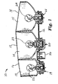
- Figure 1 is a side view of an exterior vehicle lamp assembly constructed in accordance with the present invention and showing portions of the assembly in cross-section;
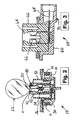
- Figure 2 is a cross-sectional view of one of the lamp sockets of Fig. 1 ;
- Figure 3 is a cross-sectional view of an alternative embodiment of a lamp socket of the present invention.
- FIG. 4 is a side view of an incandescent bulb constructed in accordance with the invention.
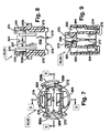
- FIG. 5 is a top plan view of the socket assembly housing
- FIG. 6 is a cross-sectional view of the housing taken along line 6--6 of FIG. 5 ;
- FIG. 7 is a top plan view of the socket assembly body
- FIG. 8 is a cross-sectional view of the body taken along line 8--8 of FIG. 7 ;
- FIG. 9 is a cross-sectional view of the body of FIG. 7 taken along line 9-9;
- the lamp socket body and sleeves used on the bulb wedge base are made from nylon 4,6 which has been found to undergo reduced outgassing when compared to at least some of the prior art plastic materials currently used in the industry.
- PA polyamide
- Noryl GTX 810 plastic lamp sockets during normal use in service is primarily the result of photo-oxidative degradation of the plastic material caused by UV light emitted from the clear incandescent bulbs used in the sockets.
- the use of a nylon 4,6 socket assembly, particularly one having a socket body formed from this material significantly reduces outgassing of the lamp socket assembly when used in its intended environment. This is due to chemical and physical characteristics of nylon 4,6 which provide improved thermal stability, including reduced socket outgassing, mechanical strength and dimensional stability, as described below;
- Fig. 1 depicts an exterior vehicle lamp assembly 10 such as can be used for rear vehicle lighting to provide separate, rearwardly-directed illumination for braking, turn signaling, and backing up.
- the assembly 10 includes a common backplate 12 to which is mounted three reflectors 13-15 that are formed as a unitary component with each of the three reflector sections 13-15 being covered by a respective lens 16-18 and having a central opening in which is located a respective lamp socket 19-21.
- Each lamp socket is individually mounted to the common backplate 12 and each contains or may operatively receive an incandescent bulb 22-24 or other known light source having an operating temperature range similar to that of an incandescent bulb, such as, for example, 200-450°F.
- Lamp assembly 10 may comprise multiple lamp sockets 19-21 and reflectors sections 13-15, or a single lamp socket and reflector section, in any combination.
- the lamp assembly 10 of FIG. 1 is only on example of such an assembly, as will be appreciated by one of ordinary skill in the art, many other configurations or embodiments of these elements are possible.
- Fig. 2 depicts further details of one of the lamp sockets 19 and its associated bulb 22.
- the lamp socket 19 is actually a socket assembly formed from a socket housing 30, a socket body 32 mounted in the housing, a set of electrical contacts 34 within the body 32 to deliver power to the bulb 22, and a corresponding set of terminals 36 (only one shown in the cross-sectional view) that are electrically connected to the contacts 34 to deliver power from the backplate 12 to the contacts 34.
- the socket body 32 is in touching contact with bulb 22, and thus is exposed to the highest operating temperatures in conjunction with the operation of assembly 10 in bulb 22, which can include temperatures of between 200-450°F.
- Socket housing 30 houses socket body 32 and is generally not in direct contact with the bulb 22 or other light source, and thus is exposed to temperatures which are somewhat lower than socket body 32.
- the extent of the temperature difference is dependent on various aspects of the design, such as the wall thickness of the socket body, the thermal conductivity of the plastic used, the size of the lamp cavity and other factors that influence the temperature drop from bulb 22 to housing 30.
- the bulb 22 is an incandescent bulb or other similar light source having a press-sealed end 40 that includes a plastic sleeve 42 having a recessed channel that allows that bulb to be resiliently held in place within the lamp socket 19.
- Suitable bulb and sleeve designs for the bulb 22 are disclosed in U.S. Patent Nos. 5,186,669 to Holman et al. and 5,486,991 to Bodem, Jr. ,.
- Suitable, existing GT-8 bulbs are also commercially available from the Wagner Lighting division of Federal-Mogul Corporation.
- the bulb 22 is mounted in an opening 50 in the body 32 of the socket 19. Located within that opening 50 are the electrical contacts 34 as well as a pair of opposing flexible retaining members, or fingers, 52. These fingers each engage the sleeve 42 at the press-sealed end of the incandescent bulb 22 and thereby retain the bulb within the opening 50. This is accomplished as shown by providing each retaining finger 52 with a protrusion that faces the opposing finger and that snaps into its corresponding recessed channel on the sleeve 42 when the bulb 22 is inserted into the opening.
- assembly 10 may include bulb 22, or be provided without bulb 22, such that bulb 22 is provided as a non-assembled portion of assembly 10, or as a completely separate component.
- socket 19 and contacts 34 are possible and within the scope of the invention.
- the electrical contacts 34 are located within the body 32 and the terminals 36 are located within the housing 30 such that the contacts and terminals are separate components that connect together at the interface between the housing and body.
- each contact is associated with a terminal and other embodiments of the socket assembly 10 could be used in which the contacts are unitary extensions of the terminals rather than separate components.
- the terminals are designed to mate with corresponding pads on the backplate 12 so that a single connector 56 can be used to supply power to all three sockets 19-21.
- U.S. Patent No. 5,536,174 to Forish U.S. Patent No. 6,139,334 to Forish et al. also discloses an alternative backplate and socket assembly which can also suitably be used without departing from the scope of the present invention. Also, rather than using a two-part socket assembly with both a housing and a body integrally attached to the housing, a single unitary housing which also incorporates the features of the body could be used.
- the body features is formed of nylon 4,6, and the remainder of the housing could be formed of a lower temperature plastic, including various other polyamides, such as nylon 6 or nylon 6,6, or blends or co-polymers thereof, as a two-part molded product, using two-shot molding, double shot molding, insert molding or similar plastic molding techniques.
- Fig. 3 shows an alternative embodiment of a lamp socket assembly 58 of the present invention which can be used in applications where the common backplate 12 is not used.
- the socket assembly 58 of Fig. 3 includes a housing 60 and a body 62 with fingers 64, as well as electrical contacts 66 and terminals 68, but also includes a connector 70 that surrounds the terminals as a unitary part of the housing 60.
- Such a socket assembly 58 could also incorporate more than one socket.
- a more complete description of lamp socket assembly 58 as well as additional socket embodiments is contained in U.S. Patent No. 5,035,643 to Forish et al. ,.
- lamp socket assemblies 19-21 and 60 are made using nylon 4,6.
- Both the housing 30, 60 and body 32, 62 may be made from nylon 4,6, although it will be appreciated that both need not be, so that, for example, a socket assembly can be constructed with only body 32, 62 made from nylon 4,6.
- body 32, 62 is formed from nylon 4,6 to obtain the advantages described herein with regard to reduced outgassing, thermal and mechanical stability as well as other advantages described herein.
- Housing 30, 60, which is exposed to lower operating temperatures, is formed from a different plastic, particularly a plastic that has reduced performance with respect to outgassing; an example of a suitable plastic is Noryl GTX 810.
- plastics having outgassing performance which is inferior to that of nylon 4,6, but still suitable for use in housing 30, 60 are believed to include all manner of polyamides, including blends and co-polymers thereof, such as nylon 6 and nylon 6,6, and blends and co-polymers thereof.
- Other engineering plastics may also be suitable for use in housing 30, 60, so long as they may be operatively attached to bodies 32, 62, either by a mechanical joint or other physical attachment means, or by a chemical bond as in the case of co-molding.
- body 32, 62 was attached to housing 30, 60 using ultrasonic welding. The welding of housing 30, 60 may be understood by reference to FIGS. 5-9 .
- housing 30 is illustrated in a top view and a cross-sectional view, respectively.
- Housing 30, 60 includes a central socket cavity 225 which is generally cylindrical in shape and into which contact insert 226 in body 32, 62 are received.
- Housing 30, 60 includes a key 240 which projects radially inwardly into cavity 225 and is used for properly orienting body 32, 62 with regard to housing 30, 60 during assembly.
- Housing 30, 60 further includes three recesses 242, 243, 244 which open into cavity 225 and which are formed into the housing in the radial wall 245 of housing 30, 60 which defines cavity 225.
- Recesses 242, 243, 244 respectively accommodate terminals 36 which are employed as the ground, major and minor electrical circuit contacts.
- a pair of contact insert keys 247 are also provided in cavity 225 to properly locate contact insert 226 in cavity 225.
- Arcuate cavities 249 in housing 30, 60 ensure that a constant wall thickness is maintained, thereby reducing the plastic consumption of housing 30, 60 without compromising its rigidity or operation.
- a plurality of energy directors or ribs 252 are a plurality of energy directors or ribs 252.
- Energy directors 252 which include triangular configured top surfaces, extend axially upwardly in cavity 225 from bottom wall 250 of the cavity. Energy directors 252 as shown ensure proper securing of body 32, 62 to housing 30, 60 when attachment by means of sonic welding is employed. Body 32, 62 is more particularly shown in FIGS. 7-9 .
- a flange 254 As best seen in FIGS. 2 and 6 , axially projecting downwardly from housing 30, 60 is a flange 254 which can be used as a grip for rotating lamp socket assembly 201 during its insertion and extraction.
- Body 32, 62 is more particularly shown in FIGS. 7-9 .
- the exterior surface of body 32, 62 includes radially projecting locking lugs 256a and 256b.
- Locking lugs 256 which are positioned around body 32, 62 at angular orientations corresponding to the configuration of mating keyed apertures in backplate assembly 12, are used to install and lock lamp socket assemblies 19, 20, 21 to backplate assembly 12. It will be appreciated that lugs 256 could be formed by axial projections of housing 30, 60.
- camming lugs are preferred, other means for installing assemblies 19, 20, 21 to backplate assembly 12, including the use of resilient fingers on one part for engaging complementary grooves in the other part, are within the scope of the invention.
- Locking lugs 256a and 256b are keyed such that socket assembly 12 cannot be inserted incorrectly when secured to backplate assembly 12.
- Each locking lug 256a and 256b includes a camming surface 258, and locking lug 256b may include a downwardly extending stop shoulder at its trailing end for abutting with an exposed portion of upper body panel.
- Camming surfaces 258 cam over the upper surface of upper panel of backplate assembly 12 during insertion of the assembled lamp socket assembly.
- the lamp socket assemblies 19, 20 and 21, and in particular a snugly fitting axial seal 31 is drawn into a sleeve 33 such that mounting flange 35 contacts the bottom edge of one of sleeves 33.
- backplate assembly 12 is captured between the bottom surfaces of lugs 256 and the top, annular-shaped surface of mounting flange 35.
- Stop shoulder 260 positively halts the rotational insertion of lamp socket assembly 19, 20, 21 at a proper rotational orientation such that the terminals are aligned with and touch contact pads, respectively.
- Body 32, 62 also includes a pair of diametrically opposed guide slots 269 defined by flanking shoulders 270.
- Guide slots 269 are bounded at their lower ends by a pair of stop ribs 272.
- Guide slots 269 and ribs 272 are structured complementarily to lamp base 217.
- Lamp base 47 includes radial protrusions on either end face (not shown) that slide within slots 269 and which abut ribs 272 in the mounted portion of lamp 22.
- Guide slots 269 serve to align lamp base 47 and ensure that a two-filament lamp 22 is being inserted, as a one-filament lamp typically used in other applications does not fit into guide slots 269.
- Body 32, 62 also includes a key slot 274 formed in the exterior surface of the body. Key slot 274 cooperates with key 240 located in central socket cavity 225 as shown in FIG. 5 to properly orient body 32,62 during assembly thereof to base 30,60.
- a slot 276 as shown in FIG. 9 is provided in the bottom portion of body 32, 62 for accommodating contact insert 226 during assembly thereof to housing 212 and body 214.
- Welding ribs 278 are provided on the bottom surface of body 214 for cooperating with energy directors 252 when body 214 is welded to housing 212. Welding ribs 278 are configured such that the voids or spaces defined between adjacent ribs serve as cavities in which terminals 233-235 are received.
- plastic components within the lamp assembly 10 can be made from the nylon 4, 6 in addition to forming the lamp socket from this material.
- all of those components exposed to the UV light emitted from the incandescent bulb, and particularly those exposed to higher heat levels, such as the body 32, 62, are formed from nylon 4,6.
- the reflectors 13-15 can also be made from the nylon 4,6.
- they can be, for example, formed from a more commonly used plastic and then metallized which provides reduced outgassing in addition to providing improved visible light reflectivity.
- the bulb 22 includes a clear glass bulb envelope 39 closed at its press-sealed end 40. Within the bulb envelope 39 is a pair of filaments 41 supported by lead wires 43 that extend through the press-sealed end 40 to exposed locations on the surface of the bulb.
- the plastic sleeve 42 is fitted over the press-sealed end 40 and covers the terminal ends of the lead wires.
- the plastic sleeve 42 is made from nylon 4,6. Bulbs 23 and 24 can be constructed in the same manner as bulb 22.
- the press-sealed end 40 of bulb 22 and plastic sleeve 42 may be replaced by a molded plastic base (not shown), such as a cylindrical plastic base, having terminals therein that attach to the terminal ends of the lead wires 43 an extend outwardly so as to be operatively electrically connected to the socket assembly.
- the plastic base may also be formed from nylon 4,6, PEI or PPA.
- the nylon 4,6 is of the type that is sold commercially under the trademark Stanyl available from Koninklijke DSM N.V., (http://www.dsm.com/en).
- This highly crystalline form of polyamide (nylon) is unlike those having non-crystalline morphologies , such as nylon 6,6 and nylon 6.
- TG glass transition temperature
- TM melt temperature
- HDT heat deflection temperature
- Nylon 4,6 and other nylons absorb considerable quantities of water which in turn affect the mechanical properties of the material by reducing the stiffness and strength while increasing the toughness. Nylon 4,6 is different, however, because of the relatively low TG.
- the glass transition temperature occurs when the material shifts from a more crystalline molecular structure to a more amorphous molecular structure. In the amorphous structure, the polymer molecules are able to move more easily, thus the material is less rigid. Due to the operating temperature of the socket body 32, 62, (anywhere from 200F-450°F) a TG in this range would affect the mechanical properties at their most critical point mechanically. Nylon 4,6 has a lower TG which is outside of this operating range. During operation of the socket assembly, the change in mechanical properties at the TG does not further negatively affect the function of the light socket. The water absorbed is driven out once the plastic sees temperatures over 100°C.
Landscapes
- Engineering & Computer Science (AREA)
- Manufacturing & Machinery (AREA)
- General Engineering & Computer Science (AREA)
- Non-Portable Lighting Devices Or Systems Thereof (AREA)
- Connecting Device With Holders (AREA)
Claims (9)
- Lampenfassungsbaugruppe (10, 58), mit:einer Fassung (19, 20, 21), die eine Öffnung (50) hat zum Empfangen eines pressverschweißten Endes einer Lichtquelle (22-24);mehreren elektrischen Kontakten (34; 66), die in der Öffnung angeordnet sind;mehreren Klemmen (36;68), von denen jede mit einem der Kontakte elektrisch verbunden ist; wobei die Fassung (19) ein Gehäuse (30; 60) und einen separaten Körper (32; 62) aufweist, der an dem Gehäuse integral befestigt und zum Empfangen der Lichtquelle ausgebildet ist;dadurch gekennzeichnet, dass der Körper (32; 62) gänzlich aus Nylon 4, 6 besteht.
- Lampenfassungsbaugruppe nach Anspruch 1, wobei das Gehäuse ein Polyamid umfasst.
- Lampenfassungsbaugruppe nach Anspruch 2, wobei das Gehäuse ein Polyamid aus einer Gruppe umfasst, die aus Nylon 6, Nylon 6, 6 und Nylon 4, 6 besteht.
- Lampenfassungsbaugruppe nach Anspruch 2, wobei das Gehäuse ein Copolymergemisch aus Polyamid und Polyphenylenoxid umfasst.
- Lampenfassungsbaugruppe nach Anspruch 1, wobei das Gehäuse und der Körper durch Ultraschallschweißen integral aneinander befestigt sind.
- Lampenkolben (22) mit:einer Glashülle (39), die einen Innenraum und ein verschlossenes Ende (40) hat;einem Licht emittierenden Element (41), das in dem Innenraum enthalten ist;mehreren Anschlussdrähten (43), welche wenigstens teilweise das Licht emittierende Element in dem Innenraum tragen, wobei sich die Anschlussdrähte aus dem Innenraum durch die Glashülle hindurch zu einer freiliegenden Stelle an dem verschlossenen Ende erstrecken;einer Büchse (42), die an der Glashülle (39) an dem verschlossenen Ende (40) befestigt ist,wobei die Büchse einen Basisteil hat, der einen inneren Durchlass aufweist, und wobei die Büchse (42) an dem verschlossenen Ende (40) so angeordnet ist, dass sich das verschlossene Ende durch den inneren Durchlass erstreckt;dadurch gekennzeichnet, dass die Büchse gänzlich aus Nylon 4, 6 besteht.
- Kraftfahrzeuglampenbaugruppe mit :einer Lampenfassungsbaugruppe (10; 58) nach Anspruch 1;einer Glühlampe (22, 23, 24), die in der Lampenfassung (19, 20, 21) lösbar befestigt ist;einem Reflektor (13, 14, 15), der sich wenigstens teilweise um die Lampe erstreckt; undeiner Linse (16, 17, 18).
- Kraftfahrzeuglampenbaugruppe nach Anspruch 7,
wobei die Fassung (19) wenigstens ein flexibles Halteteil (52) aufweist, das in der Öffnung (50) angeordnet ist, um die Glühlampe (22) zu erfassen und dadurch die Lampe in der Öffnung festzuhalten. - Kraftfahrzeuglampenbaugruppe nach Anspruch 7 oder 8, wobei die Lampe ein pressverschweißtes Ende (40) aufweist, das eine Kunststoffbüchse (42) in Kontakt mit dem (den) Halteteil(en) hat, wobei die Kunststoffbüchse (42) ein Teil aus der Gruppe umfasst, die aus Nylon 4, 6 Polyetheremid (PEI) und Polyphtalamid (PPA) besteht.
Applications Claiming Priority (3)
| Application Number | Priority Date | Filing Date | Title |
|---|---|---|---|
| US73811405P | 2005-11-18 | 2005-11-18 | |
| US11/561,045 US7604386B2 (en) | 2005-11-18 | 2006-11-17 | Lamp assembly having a socket made from high temperature plastic |
| PCT/US2006/061086 WO2007062344A2 (en) | 2005-11-18 | 2006-11-18 | Lamp assembly having a socket made from high temperature plastic |
Publications (3)
| Publication Number | Publication Date |
|---|---|
| EP1948478A2 EP1948478A2 (de) | 2008-07-30 |
| EP1948478A4 EP1948478A4 (de) | 2010-05-19 |
| EP1948478B1 true EP1948478B1 (de) | 2011-12-21 |
Family
ID=38068636
Family Applications (1)
| Application Number | Title | Priority Date | Filing Date |
|---|---|---|---|
| EP06846349A Not-in-force EP1948478B1 (de) | 2005-11-18 | 2006-11-18 | Lampenbaugruppe mit einem sockel aus hochtemperatur-kunststoff |
Country Status (6)
| Country | Link |
|---|---|
| US (1) | US7604386B2 (de) |
| EP (1) | EP1948478B1 (de) |
| JP (2) | JP5400385B2 (de) |
| CN (1) | CN101360630B (de) |
| BR (1) | BRPI0618628A2 (de) |
| WO (1) | WO2007062344A2 (de) |
Families Citing this family (13)
| Publication number | Priority date | Publication date | Assignee | Title |
|---|---|---|---|---|
| US7527393B2 (en) | 2005-01-18 | 2009-05-05 | Musco Corporation | Apparatus and method for eliminating outgassing of sports lighting fixtures |
| US8342727B2 (en) * | 2005-10-26 | 2013-01-01 | Federal-Mogul Ignition Company | Molded electrical socket |
| US7585187B2 (en) * | 2007-09-13 | 2009-09-08 | Tyco Electronics Corporation | LED socket |
| JP5047843B2 (ja) * | 2008-03-06 | 2012-10-10 | 株式会社小糸製作所 | 航空機用外部照明灯 |
| EP2287644B1 (de) * | 2009-08-18 | 2014-04-09 | Mitsubishi Electric Corporation | Lichtquellenvorrichtung und Herstellungsverfahren dafür |
| JP5566770B2 (ja) * | 2010-05-17 | 2014-08-06 | 株式会社小糸製作所 | 車両用灯具と車両用灯具の組立方法 |
| KR101300907B1 (ko) * | 2010-10-01 | 2013-08-27 | 소닉스자펜 주식회사 | 반사갓연결장치, 이를 포함하는 반사갓결합모듈 및 등기구 |
| US8562193B2 (en) * | 2010-11-11 | 2013-10-22 | Automotive Lighting Italia S.P.A. | Wedge-base bulb socket and automotive light for motor vehicles and similar provided with said socket |
| JP5896406B2 (ja) * | 2012-01-26 | 2016-03-30 | 矢崎総業株式会社 | バルブソケット及び照明装置 |
| US8956019B2 (en) * | 2012-08-27 | 2015-02-17 | Ideal Industries, Inc. | Methods and apparatus for grounding an electrical device via a lampholder |
| US9174568B2 (en) * | 2013-06-26 | 2015-11-03 | Sabic Global Technologies B.V. | Headlamp mounting bracket energy absorber |
| JP6211326B2 (ja) * | 2013-07-22 | 2017-10-11 | 株式会社小糸製作所 | 光源装置および車両用灯具 |
| US10680380B2 (en) * | 2018-09-13 | 2020-06-09 | Aptiv Technologies Limited | Angled electrical connector assembly and method of manufacturing same |
Family Cites Families (43)
| Publication number | Priority date | Publication date | Assignee | Title |
|---|---|---|---|---|
| US4724353A (en) * | 1984-02-16 | 1988-02-09 | Gte Products Corporation | Electric lamp with insulating base |
| US4647132A (en) * | 1984-12-17 | 1987-03-03 | Ford Motor Company | Retaining mechanism for securing a lamp base within a socket |
| JPS63161056A (ja) * | 1986-12-25 | 1988-07-04 | Japan Synthetic Rubber Co Ltd | 難燃性ポリアミド組成物 |
| US5000702A (en) * | 1989-05-17 | 1991-03-19 | Zanxx, Inc. | Low profile lamp socket assembly and method of making |
| US5035643A (en) * | 1989-05-17 | 1991-07-30 | Zanxx, Inc. | Axial low profile lamp socket assembly |
| US4940422A (en) * | 1989-05-17 | 1990-07-10 | Zanxx, Inc. | Low profile lamp socket assembly |
| US4958429A (en) * | 1989-05-17 | 1990-09-25 | Zanxx, Inc. | Method of making low profile lamp socket assembly |
| US4979082A (en) * | 1989-06-02 | 1990-12-18 | Gte Products Corporation | Relieved plastic lamp base |
| US5113104A (en) | 1989-10-19 | 1992-05-12 | General Electric Company | Structured product dynamoelectric machine |
| US5237231A (en) * | 1989-10-19 | 1993-08-17 | General Electric Company | Structured product dynamoelectric machine |
| US5186669A (en) * | 1990-02-01 | 1993-02-16 | Cooper Industries, Inc. | Incandescent lamp |
| US5172026A (en) * | 1990-05-21 | 1992-12-15 | Hall Rolland B | Plug in lamp |
| EP0725074A3 (de) * | 1992-04-20 | 1996-11-20 | Sankyo Co | Verbindungen zur Verwendung also Zwischenprodukte zur Herstellung von Androst-3,5-dien-3-carboxy-Derivaten |
| US5492980A (en) * | 1992-10-12 | 1996-02-20 | Kishimoto Sangyo Co., Ltd. | Thermoplastic molding resin composition |
| JPH0737272Y2 (ja) * | 1993-06-16 | 1995-08-23 | 第一電装部品株式会社 | 接続具の取付け構成体 |
| JP3102440B2 (ja) * | 1994-02-01 | 2000-10-23 | 旭化成工業株式会社 | 新規な樹脂組成物 |
| JPH0860001A (ja) * | 1994-06-14 | 1996-03-05 | Toray Ind Inc | 繊維強化熱可塑性樹脂ペレットおよびその製造方法 |
| US5486991A (en) * | 1994-07-29 | 1996-01-23 | Federal-Mogul Corporation | Vehicle signal lamp assembly |
| US5536174A (en) | 1994-09-29 | 1996-07-16 | Cooper Industries, Inc. | Lamp socket assembly for use with a backplate assembly and method of making same |
| SE504657C2 (sv) * | 1995-07-03 | 1997-03-24 | Sunds Defibrator Ind Ab | Tätningsanordning |
| JP3267856B2 (ja) * | 1996-03-12 | 2002-03-25 | 株式会社小糸製作所 | 放電灯 |
| US6210014B1 (en) * | 1997-01-21 | 2001-04-03 | Gore Enterprise Holdings, Inc. | System for reducing condensation in enclosed lamp housings |
| JPH1125919A (ja) * | 1997-07-04 | 1999-01-29 | Moriyama Sangyo Kk | 電球装置および照明装置 |
| JPH1180568A (ja) * | 1997-07-11 | 1999-03-26 | Toray Ind Inc | 難燃性樹脂組成物 |
| US6012830A (en) * | 1998-06-23 | 2000-01-11 | Valeo Sylvania L.L.C. | Light shield for a vehicle headlamp |
| US6139334A (en) * | 1998-09-16 | 2000-10-31 | Cooper Automotive Products, Inc. | Integral socket backplate |
| JP4714965B2 (ja) * | 1999-11-01 | 2011-07-06 | 東レ株式会社 | 気体および/または液体バリア部品用強化樹脂組成物および成形品 |
| JP3988177B2 (ja) * | 2000-02-02 | 2007-10-10 | ニプロ株式会社 | ウェッジベース電球 |
| JP2001226503A (ja) * | 2000-02-16 | 2001-08-21 | Asahi Kasei Corp | 機能性樹脂材料 |
| JP2002075292A (ja) * | 2000-08-31 | 2002-03-15 | Harison Toshiba Lighting Corp | 管球用ホルダーおよび管球 |
| JP2002080724A (ja) * | 2000-09-04 | 2002-03-19 | Sumitomo Chem Co Ltd | 熱可塑性樹脂組成物およびその成形体 |
| US6469443B1 (en) * | 2001-03-20 | 2002-10-22 | Federal-Mogul World-Wide, Inc. | Cadmium-free amber automotive lamp |
| EP1384292A4 (de) | 2001-03-20 | 2007-08-15 | Federal Mogul Corp | Polyeterimidlampensockelbaugruppe |
| DE60233559D1 (de) * | 2001-04-03 | 2009-10-15 | Kureha Corp | Ic-fassung |
| US20040165411A1 (en) * | 2002-03-20 | 2004-08-26 | Heath Eric W. | Polyetherimide lamp socket assembly |
| AU2003220413A1 (en) * | 2002-03-21 | 2003-10-08 | Federal-Mogul Corporation | High temperature lamp |
| WO2004015331A1 (en) * | 2002-08-07 | 2004-02-19 | Koninklijke Philips Electronics N.V. | Device for placing a lamp in a reflector |
| CN1935897B (zh) * | 2002-09-09 | 2013-11-06 | 索尼株式会社 | 树脂组合物 |
| US7138448B2 (en) * | 2002-11-04 | 2006-11-21 | Ciba Specialty Chemicals Corporation | Flame retardant compositions |
| WO2004069932A1 (ja) * | 2003-02-04 | 2004-08-19 | Sony Corporation | 樹脂組成物及び樹脂成型体の製造方法 |
| DE10312806A1 (de) * | 2003-03-21 | 2004-09-30 | Patent-Treuhand-Gesellschaft für elektrische Glühlampen mbH | Lampe |
| JP4254296B2 (ja) * | 2003-03-25 | 2009-04-15 | ニプロ株式会社 | 自動車用電球 |
| JP2005194515A (ja) * | 2003-12-12 | 2005-07-21 | Asahi Kasei Chemicals Corp | 芳香族基含有熱可塑性樹脂組成物 |
-
2006
- 2006-11-17 US US11/561,045 patent/US7604386B2/en active Active
- 2006-11-18 JP JP2008541501A patent/JP5400385B2/ja not_active Expired - Fee Related
- 2006-11-18 CN CN2006800513699A patent/CN101360630B/zh not_active Expired - Fee Related
- 2006-11-18 BR BRPI0618628-9A patent/BRPI0618628A2/pt not_active IP Right Cessation
- 2006-11-18 EP EP06846349A patent/EP1948478B1/de not_active Not-in-force
- 2006-11-18 WO PCT/US2006/061086 patent/WO2007062344A2/en not_active Ceased
-
2012
- 2012-06-26 JP JP2012143000A patent/JP5584735B2/ja not_active Expired - Fee Related
Also Published As
| Publication number | Publication date |
|---|---|
| EP1948478A4 (de) | 2010-05-19 |
| EP1948478A2 (de) | 2008-07-30 |
| BRPI0618628A2 (pt) | 2011-09-06 |
| CN101360630A (zh) | 2009-02-04 |
| JP5400385B2 (ja) | 2014-01-29 |
| US7604386B2 (en) | 2009-10-20 |
| CN101360630B (zh) | 2012-10-10 |
| US20070139948A1 (en) | 2007-06-21 |
| WO2007062344A2 (en) | 2007-05-31 |
| JP5584735B2 (ja) | 2014-09-03 |
| WO2007062344A3 (en) | 2008-08-07 |
| JP2009516896A (ja) | 2009-04-23 |
| JP2012216558A (ja) | 2012-11-08 |
Similar Documents
| Publication | Publication Date | Title |
|---|---|---|
| JP5584735B2 (ja) | ランプソケットアセンブリ、電球、および自動車のランプソケットアセンブリ | |
| CN1097283C (zh) | 无粘合剂地插入灯座的电灯及该电灯和反光罩的组合件 | |
| US4760506A (en) | Light bulb mounting structure in automotive lamp | |
| JP4662524B2 (ja) | 前照灯用ランプ | |
| CN1291436C (zh) | 前照灯灯泡 | |
| US6210020B1 (en) | Capped electric lamp | |
| US8651899B2 (en) | Lamp socket assembly and method | |
| JP4746386B2 (ja) | くさび形ベースランプのためのセンタリングリングを備えるソケット | |
| US7988347B2 (en) | Fastening system and lamp having a fastening system | |
| CN1906733B (zh) | 具有改进的热传导性的灯座 | |
| EP1384292A1 (de) | Polyeterimidlampensockelbaugruppe | |
| CN101142722A (zh) | 用于灯的灯座 | |
| JP2010524152A (ja) | バルブソケット | |
| US20030128548A1 (en) | License plate lamp | |
| JPH1031901A (ja) | 灯具のバルブ固定構造 | |
| WO2008149266A1 (en) | Motor vehicle lamp |
Legal Events
| Date | Code | Title | Description |
|---|---|---|---|
| PUAI | Public reference made under article 153(3) epc to a published international application that has entered the european phase |
Free format text: ORIGINAL CODE: 0009012 |
|
| 17P | Request for examination filed |
Effective date: 20080528 |
|
| AK | Designated contracting states |
Kind code of ref document: A2 Designated state(s): AT BE BG CH CY CZ DE DK EE ES FI FR GB GR HU IE IS IT LI LT LU LV MC NL PL PT RO SE SI SK TR |
|
| AX | Request for extension of the european patent |
Extension state: AL BA HR MK RS |
|
| R17D | Deferred search report published (corrected) |
Effective date: 20080807 |
|
| RIC1 | Information provided on ipc code assigned before grant |
Ipc: H01R 33/00 20060101ALI20090114BHEP Ipc: B60Q 1/00 20060101AFI20090114BHEP |
|
| DAX | Request for extension of the european patent (deleted) | ||
| RBV | Designated contracting states (corrected) |
Designated state(s): DE GB |
|
| A4 | Supplementary search report drawn up and despatched |
Effective date: 20100416 |
|
| RIC1 | Information provided on ipc code assigned before grant |
Ipc: H01R 33/00 20060101ALI20110414BHEP Ipc: B60Q 1/00 20060101AFI20110414BHEP |
|
| GRAP | Despatch of communication of intention to grant a patent |
Free format text: ORIGINAL CODE: EPIDOSNIGR1 |
|
| GRAS | Grant fee paid |
Free format text: ORIGINAL CODE: EPIDOSNIGR3 |
|
| GRAA | (expected) grant |
Free format text: ORIGINAL CODE: 0009210 |
|
| AK | Designated contracting states |
Kind code of ref document: B1 Designated state(s): DE GB |
|
| REG | Reference to a national code |
Ref country code: GB Ref legal event code: FG4D |
|
| REG | Reference to a national code |
Ref country code: DE Ref legal event code: R096 Ref document number: 602006026619 Country of ref document: DE Effective date: 20120308 |
|
| PLBE | No opposition filed within time limit |
Free format text: ORIGINAL CODE: 0009261 |
|
| STAA | Information on the status of an ep patent application or granted ep patent |
Free format text: STATUS: NO OPPOSITION FILED WITHIN TIME LIMIT |
|
| 26N | No opposition filed |
Effective date: 20120924 |
|
| REG | Reference to a national code |
Ref country code: DE Ref legal event code: R097 Ref document number: 602006026619 Country of ref document: DE Effective date: 20120924 |
|
| REG | Reference to a national code |
Ref country code: DE Ref legal event code: R082 Ref document number: 602006026619 Country of ref document: DE Representative=s name: SCHUMACHER & WILLSAU PATENTANWALTSGESELLSCHAFT, DE |
|
| PGFP | Annual fee paid to national office [announced via postgrant information from national office to epo] |
Ref country code: DE Payment date: 20121130 Year of fee payment: 7 |
|
| PGFP | Annual fee paid to national office [announced via postgrant information from national office to epo] |
Ref country code: GB Payment date: 20130117 Year of fee payment: 7 |
|
| GBPC | Gb: european patent ceased through non-payment of renewal fee |
Effective date: 20131118 |
|
| PG25 | Lapsed in a contracting state [announced via postgrant information from national office to epo] |
Ref country code: DE Free format text: LAPSE BECAUSE OF NON-PAYMENT OF DUE FEES Effective date: 20140603 |
|
| REG | Reference to a national code |
Ref country code: DE Ref legal event code: R119 Ref document number: 602006026619 Country of ref document: DE Effective date: 20140603 |
|
| PG25 | Lapsed in a contracting state [announced via postgrant information from national office to epo] |
Ref country code: GB Free format text: LAPSE BECAUSE OF NON-PAYMENT OF DUE FEES Effective date: 20131118 |