EP1949927B1 - Nadel für Injektionspen mit passiver Sicherheitsfunktion für das Nicht-Injektions-Ende - Google Patents
Nadel für Injektionspen mit passiver Sicherheitsfunktion für das Nicht-Injektions-Ende Download PDFInfo
- Publication number
- EP1949927B1 EP1949927B1 EP08100578.7A EP08100578A EP1949927B1 EP 1949927 B1 EP1949927 B1 EP 1949927B1 EP 08100578 A EP08100578 A EP 08100578A EP 1949927 B1 EP1949927 B1 EP 1949927B1
- Authority
- EP
- European Patent Office
- Prior art keywords
- shield
- needle
- hub
- pen injector
- pen
- Prior art date
- Legal status (The legal status is an assumption and is not a legal conclusion. Google has not performed a legal analysis and makes no representation as to the accuracy of the status listed.)
- Not-in-force
Links
- 238000002347 injection Methods 0.000 title claims description 67
- 239000007924 injection Substances 0.000 title claims description 67
- 229940090048 pen injector Drugs 0.000 claims description 65
- 239000000853 adhesive Substances 0.000 claims description 2
- 230000001070 adhesive effect Effects 0.000 claims description 2
- 230000013011 mating Effects 0.000 claims description 2
- 239000000463 material Substances 0.000 claims 1
- 230000001681 protective effect Effects 0.000 description 7
- 230000008901 benefit Effects 0.000 description 5
- 229940079593 drug Drugs 0.000 description 4
- 239000003814 drug Substances 0.000 description 4
- 206010069803 Injury associated with device Diseases 0.000 description 3
- 208000012266 Needlestick injury Diseases 0.000 description 2
- 208000027418 Wounds and injury Diseases 0.000 description 2
- 230000004888 barrier function Effects 0.000 description 2
- 239000008280 blood Substances 0.000 description 2
- 210000004369 blood Anatomy 0.000 description 2
- 230000006378 damage Effects 0.000 description 2
- 230000036512 infertility Effects 0.000 description 2
- 208000014674 injury Diseases 0.000 description 2
- NOESYZHRGYRDHS-UHFFFAOYSA-N insulin Chemical compound N1C(=O)C(NC(=O)C(CCC(N)=O)NC(=O)C(CCC(O)=O)NC(=O)C(C(C)C)NC(=O)C(NC(=O)CN)C(C)CC)CSSCC(C(NC(CO)C(=O)NC(CC(C)C)C(=O)NC(CC=2C=CC(O)=CC=2)C(=O)NC(CCC(N)=O)C(=O)NC(CC(C)C)C(=O)NC(CCC(O)=O)C(=O)NC(CC(N)=O)C(=O)NC(CC=2C=CC(O)=CC=2)C(=O)NC(CSSCC(NC(=O)C(C(C)C)NC(=O)C(CC(C)C)NC(=O)C(CC=2C=CC(O)=CC=2)NC(=O)C(CC(C)C)NC(=O)C(C)NC(=O)C(CCC(O)=O)NC(=O)C(C(C)C)NC(=O)C(CC(C)C)NC(=O)C(CC=2NC=NC=2)NC(=O)C(CO)NC(=O)CNC2=O)C(=O)NCC(=O)NC(CCC(O)=O)C(=O)NC(CCCNC(N)=N)C(=O)NCC(=O)NC(CC=3C=CC=CC=3)C(=O)NC(CC=3C=CC=CC=3)C(=O)NC(CC=3C=CC(O)=CC=3)C(=O)NC(C(C)O)C(=O)N3C(CCC3)C(=O)NC(CCCCN)C(=O)NC(C)C(O)=O)C(=O)NC(CC(N)=O)C(O)=O)=O)NC(=O)C(C(C)CC)NC(=O)C(CO)NC(=O)C(C(C)O)NC(=O)C1CSSCC2NC(=O)C(CC(C)C)NC(=O)C(NC(=O)C(CCC(N)=O)NC(=O)C(CC(N)=O)NC(=O)C(NC(=O)C(N)CC=1C=CC=CC=1)C(C)C)CC1=CN=CN1 NOESYZHRGYRDHS-UHFFFAOYSA-N 0.000 description 2
- 230000004048 modification Effects 0.000 description 2
- 238000012986 modification Methods 0.000 description 2
- 208000005176 Hepatitis C Diseases 0.000 description 1
- 102000002265 Human Growth Hormone Human genes 0.000 description 1
- 108010000521 Human Growth Hormone Proteins 0.000 description 1
- 239000000854 Human Growth Hormone Substances 0.000 description 1
- 102000004877 Insulin Human genes 0.000 description 1
- 108090001061 Insulin Proteins 0.000 description 1
- 208000001132 Osteoporosis Diseases 0.000 description 1
- 241000700605 Viruses Species 0.000 description 1
- 230000001387 anti-histamine Effects 0.000 description 1
- 229940125715 antihistaminic agent Drugs 0.000 description 1
- 239000000739 antihistaminic agent Substances 0.000 description 1
- 244000078885 bloodborne pathogen Species 0.000 description 1
- 238000011109 contamination Methods 0.000 description 1
- 201000010099 disease Diseases 0.000 description 1
- 208000037265 diseases, disorders, signs and symptoms Diseases 0.000 description 1
- 230000000694 effects Effects 0.000 description 1
- 239000012530 fluid Substances 0.000 description 1
- 239000011888 foil Substances 0.000 description 1
- 208000002672 hepatitis B Diseases 0.000 description 1
- 208000015181 infectious disease Diseases 0.000 description 1
- 229940125396 insulin Drugs 0.000 description 1
- 238000002483 medication Methods 0.000 description 1
- 239000002184 metal Substances 0.000 description 1
- 238000004806 packaging method and process Methods 0.000 description 1
- 229920000642 polymer Polymers 0.000 description 1
- 230000002265 prevention Effects 0.000 description 1
- 230000002459 sustained effect Effects 0.000 description 1
Images

Classifications
-
- A—HUMAN NECESSITIES
- A61—MEDICAL OR VETERINARY SCIENCE; HYGIENE
- A61M—DEVICES FOR INTRODUCING MEDIA INTO, OR ONTO, THE BODY; DEVICES FOR TRANSDUCING BODY MEDIA OR FOR TAKING MEDIA FROM THE BODY; DEVICES FOR PRODUCING OR ENDING SLEEP OR STUPOR
- A61M5/00—Devices for bringing media into the body in a subcutaneous, intra-vascular or intramuscular way; Accessories therefor, e.g. filling or cleaning devices, arm-rests
- A61M5/178—Syringes
- A61M5/31—Details
- A61M5/32—Needles; Details of needles pertaining to their connection with syringe or hub; Accessories for bringing the needle into, or holding the needle on, the body; Devices for protection of needles
- A61M5/34—Constructions for connecting the needle, e.g. to syringe nozzle or needle hub
- A61M5/347—Constructions for connecting the needle, e.g. to syringe nozzle or needle hub rotatable, e.g. bayonet or screw
-
- A—HUMAN NECESSITIES
- A61—MEDICAL OR VETERINARY SCIENCE; HYGIENE
- A61M—DEVICES FOR INTRODUCING MEDIA INTO, OR ONTO, THE BODY; DEVICES FOR TRANSDUCING BODY MEDIA OR FOR TAKING MEDIA FROM THE BODY; DEVICES FOR PRODUCING OR ENDING SLEEP OR STUPOR
- A61M5/00—Devices for bringing media into the body in a subcutaneous, intra-vascular or intramuscular way; Accessories therefor, e.g. filling or cleaning devices, arm-rests
- A61M5/178—Syringes
- A61M5/31—Details
- A61M5/32—Needles; Details of needles pertaining to their connection with syringe or hub; Accessories for bringing the needle into, or holding the needle on, the body; Devices for protection of needles
- A61M5/3205—Apparatus for removing or disposing of used needles or syringes, e.g. containers; Means for protection against accidental injuries from used needles
- A61M5/321—Means for protection against accidental injuries by used needles
- A61M5/3243—Means for protection against accidental injuries by used needles being axially-extensible, e.g. protective sleeves coaxially slidable on the syringe barrel
- A61M5/326—Fully automatic sleeve extension, i.e. in which triggering of the sleeve does not require a deliberate action by the user
-
- A—HUMAN NECESSITIES
- A61—MEDICAL OR VETERINARY SCIENCE; HYGIENE
- A61M—DEVICES FOR INTRODUCING MEDIA INTO, OR ONTO, THE BODY; DEVICES FOR TRANSDUCING BODY MEDIA OR FOR TAKING MEDIA FROM THE BODY; DEVICES FOR PRODUCING OR ENDING SLEEP OR STUPOR
- A61M5/00—Devices for bringing media into the body in a subcutaneous, intra-vascular or intramuscular way; Accessories therefor, e.g. filling or cleaning devices, arm-rests
- A61M5/178—Syringes
- A61M5/31—Details
- A61M5/32—Needles; Details of needles pertaining to their connection with syringe or hub; Accessories for bringing the needle into, or holding the needle on, the body; Devices for protection of needles
- A61M5/3205—Apparatus for removing or disposing of used needles or syringes, e.g. containers; Means for protection against accidental injuries from used needles
- A61M5/321—Means for protection against accidental injuries by used needles
- A61M5/3243—Means for protection against accidental injuries by used needles being axially-extensible, e.g. protective sleeves coaxially slidable on the syringe barrel
- A61M5/3245—Constructional features thereof, e.g. to improve manipulation or functioning
- A61M2005/3254—Shielding of proximal needles, e.g. for pen needles
-
- A—HUMAN NECESSITIES
- A61—MEDICAL OR VETERINARY SCIENCE; HYGIENE
- A61M—DEVICES FOR INTRODUCING MEDIA INTO, OR ONTO, THE BODY; DEVICES FOR TRANSDUCING BODY MEDIA OR FOR TAKING MEDIA FROM THE BODY; DEVICES FOR PRODUCING OR ENDING SLEEP OR STUPOR
- A61M5/00—Devices for bringing media into the body in a subcutaneous, intra-vascular or intramuscular way; Accessories therefor, e.g. filling or cleaning devices, arm-rests
- A61M5/178—Syringes
- A61M5/24—Ampoule syringes, i.e. syringes with needle for use in combination with replaceable ampoules or carpules, e.g. automatic
- A61M5/2455—Ampoule syringes, i.e. syringes with needle for use in combination with replaceable ampoules or carpules, e.g. automatic with sealing means to be broken or opened
- A61M5/2466—Ampoule syringes, i.e. syringes with needle for use in combination with replaceable ampoules or carpules, e.g. automatic with sealing means to be broken or opened by piercing without internal pressure increase
Definitions
- the invention is directed to a passive safety shield which may be associated with an injection pen needle to shield the non-injection end of the needle.
- U.S. Patent No. 6,986,760 B2 assigned to the assignee of the present application, the disclosure of which is herein incorporated by reference in its entirety, teaches a pen needle and safety shield system wherein a safety shield, which normally encloses the needle cannula prior to use, permits retraction of the safety shield during injection and automatically extends and locks the shield in the extended enclosed position following use.
- the pen needle also prevents retraction of the shield during assembly of the shield and needle cannula and hub assembly on the pen injector.
- An injection pen needle according to the first part of claim 1 is disclosed in US 5, 336,200 A .
- This injection pen needle comprises a needle hub carrying a needle having an injection and a non-injection end.
- a protective tube bears against the end of the hub.
- the protective tube is deformable and it is compressed when a carpule is moved towards the needle hub. When the carpule is withdrawn, the protective tube takes its original shape and covers the non-injection needle tip.
- the protective tube is not fixed to the needle hub and may be lost.
- a double-ended cannula as disclosed in WO 89/11,304 is provided with two protective sleeves serving as adapters.
- the protective sleeves have bayonet sockets or similar devices arranged to be fitted into a corresponding fitment comprised in a blood tube holder.
- An injection pen needle witha non-injection end passive safety shield for an injection pen needle according to the present invention is defined in claim 1.
- a biasing element (such as a spring) may bias the shield toward the pen injector to insure that the shield covers the non-injection end of the needle when the pen injector is removed from the hub.
- the safety shield system according to the invention is "passive" because shielding of the non-injection end is automatic upon removing the pen-injector. User-implemented steps are not required to shield the non-injection end of the needle.
- injection end and “non-injection end” refer to directions on the device.
- the injection end refers to a direction toward the end of the device that is normally pressed against a patient's body during an injection (the distal end), while the non-injection end refers to the opposite direction, toward the proximal end, whether the patient injects himself or herself, whether someone else administers the injection, and whether or not an injection is actually accomplished.
- the non-injection end shield "covers” or “shrouds” the needle when the tip of the needle does not extend beyond the end wall of the shield, notwithstanding that the tip of the needle may be quite close to the aperture in the shield, and exposed to view.
- an injection pen needle 100 generally includes a tubular body referred to herein as pen injector 60 including a vial 90 for holding a fluid, such as insulin, anti-histamines, etc., which may be accessed by the needle 110.
- a fluid such as insulin, anti-histamines, etc.
- a needle hub 70 on which the needle is mounted, receives the pen injector in a cup-shaped recess 80 on the non-injection side of the hub.
- the hub 70 and pen injector 60 are threaded to engage one another.
- the needle cannula 110 extends into an end portion of the hub 70 and includes a non-injection end extending into the body portion of the pen injector, to pierce the closure of the vial 90.
- the opposed injection end of the needle is for injection, typically into the patient.
- Fig. 1 shows a first embodiment, in which the shield member 10 is situated on the base of the pen needle hub 70 prior to fitting the pen injector.
- the needle 110 is not shrouded by the shield 10 when the pen injector is inserted.
- the shield has threads 12 engaging with threads 14 on the hub and a small interference element (not shown) or frictional force may be used to prevent the shield moving during distribution and/or prior to use. It will be understood that any force required to retain the shield in this position should be less than the force required to retract the shield into the hub when the pen injector is removed so that the shield moves with the pen injector, as intended.
- the shield 10 may sit so that it covers or protrudes from recess 80 in the hub 70 covering the non-injection end of the needle before the pen injector is inserted.
- the pen injector 60 may be engaged with the shield 10, such as with one or more mating tabs and recesses, and then both the shield 10 and the pen injector 60 may be installed into the recess 80, such as by pushing and/or screwing.
- a retaining element Prior to engaging the pen injector in the hub, a retaining element may be used to retain the shield in a position covering the non-injection end of the needle.
- a raised portion 120 adjacent the thread may be used to prevent movement of the shield on the thread until the user installs the pen injector.
- the shield may be held in position by a frictional fit, which is overcome when the pen injector is installed.
- Aperture 140 on the shield member 10 permits passage of the needle 110.
- a raised feature such as ridge 150 around the aperture 140, may optionally be used to provide additional height to shroud the non-injection end of the needle prior to the user installing the pen injector or after the pen injector has been removed.
- the raised ridge 150 may be accommodated in a free space immediately above the vial septum area found in prior art pen injector devices. As the rest of the shield 10 may have reduced height compared with the ridge 150, it is easier to accommodate the shield member into the hub of such prior art devices with less modification. Specifically, less height is required in the hub to accommodate the shield.
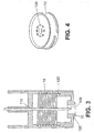
- Fig. 2 shows the shield member 10 in the pen needle hub, with the pen injector tip fully engaged with the hub.
- the non-injection end of the needle 110 pierces septum 50.
- the shield member 10 engages the pen injector 60, so that when the pen is removed, the shield rotates with it and it is drawn into the free space in the hub.
- Fig. 3 shows the shield member 10 in its protecting position, where the non-injection end surface provides an effective barrier to accessing the non-injection end of the needle tip.
- a lockout member (not shown) adjacent the thread on the shield may be utilized to prevent the shield member 10 from retreating into the hub, once the pen injector has been removed.
- a protuberance on the thread could create an interference such that shield 10 does not move down the threads in the hub.
- Another lockout element could be provided, as known in the art, to prevent the shield from retreating into the hub.
- Fig. 4 shows a perspective view of the shield member 10 having a ring of teeth 130 which engage with the septum of the vial in the pen injector.
- the teeth 130 drive the shield in the threads in the hub and act as an engaging element to engage the shield 10 with the pen injector 60, or with the septum of the vial inside the pen injector.
- one or more adhesive or grippy polymer elements arranged around the surface of the shield member may also be used.
- the engaging element temporarily attaches the shield to the pen injector so that when the pen injector is unscrewed from the hub after an injection has been administered, the shield is rotated with the pen injector and retracted with it to cover the non-injection end of the needle.
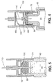
- Fig. 5 shows the pen injector 60 fully screwed home.
- the teeth 130 on the shield member are engaged with the pen injector's septum, such that as the pen is unscrewed, the rotating of the pen injector causes the shield to rotate with it and so that it can be driven up the thread in the pen needle's hub.
- Fig. 6 also depicts the pen injector fully screwed home, and further depicts a biasing member 160 biasing the shield member toward the pen injector in the hub, so that the shield member securely engages the pen injector when the pen injector is withdrawn after an injection has been administered.
- biasing member 160 is shown as being integral with the shield member 10, biasing the shield toward the pen injector and pressing against the inside surface of the injection end of the hub. That is, the shield and biasing member constitute one piece.
- Such an integral member may conveniently be made from plastic or metal.
- a separate spring element may be used to bias the shield in toward the non-injection end of the device.
- the safety shield By shielding the non-injection end of a pen needle device, the safety shield according to the invention provides a clear benefit to healthcare professionals in the hospital or clinic setting.
- the shield may have additional advantages of hiding the needle from view, which is an advantage for patients who are particularly needle-averse.
- safe disposal of the needle hub is facilitated according to the invention, as the needle is essentially enclosed once an injection is administered.
- a particular advantage of the safety shield is its simplicity of use, requiring little or no implementation from the user. Because the shield is built into the hub, there is no cap or other separate cover that can be separated from the device and lost.
- a pen needle according to the invention may utilize a range of needle lengths and gauges.
- the pen needle is small, to minimize patient discomfort, effect a successful injection, and enhance portability and ease of use.
- the shield could effectively be used with 29, 30 and 31 gauge needles having injection lengths of 5 mm, 8 mm and 12 mm, although these examples are not limiting. Visible coding schemes may be added to indicate the type of injection to be administered, the size and gauge of needle, to indicate engagement of the pen injector, that the shield has moved or locked out, etc.
- the pen needle will, in most cases, be packaged in an outer shield with a foil sterility barrier, as commonly practiced in the art. Alternatively, other packaging to ensure sterility may be provided.
Landscapes
- Health & Medical Sciences (AREA)
- Engineering & Computer Science (AREA)
- Hematology (AREA)
- Anesthesiology (AREA)
- Biomedical Technology (AREA)
- Heart & Thoracic Surgery (AREA)
- Vascular Medicine (AREA)
- Life Sciences & Earth Sciences (AREA)
- Animal Behavior & Ethology (AREA)
- General Health & Medical Sciences (AREA)
- Public Health (AREA)
- Veterinary Medicine (AREA)
- Environmental & Geological Engineering (AREA)
- Infusion, Injection, And Reservoir Apparatuses (AREA)
Claims (10)
- Injektions-Pen-Nadel mit passiver Sicherheitsschutzvorrichtung (100) für das Nicht-Injektions-Ende, mit:einem Nadelansatz (70),einer Nadel (110), die an dem Ansatz (70) befestigt ist und ein Injektionsende und ein Nicht-Injektions-Ende hat, wobei der Ansatz (70) eine das Nicht-Injektions-Ende der Nadel (110) umgebende Ausnehmung (80) zur Aufnahme eines Pen-Injektors (60) aufweist;einem Schutzteil (10), das in der Ausnehmung (80) des Ansatzes (70) angeordnet ist und eine Öffnung (140) aufweist, die das Hindurchtreten der Nadel (110) erlaubt,einem Element (130), welches das Schutzteil (10) in Zusammengriff mit dem Pen-Injektor (60) bringt, bevor oder wenn der Pen-Injektor (60) von dem Ansatz (70) aufgenommen wird, wodurch sich das Schutzteil (10) mit dem Pen-Injektor (60) bewegt und das Nicht-Injektions-Ende der Nadel (110) abdeckt, wenn der Pen-Injektor (60) von dem Ansatz (70) abgenommen wird,dadurch gekennzeichnet, dass
die Injektions-Pen-Nadel ferner an dem Ansatz (70) ein Gewinde (14) zum Zusammengriff mit einem Gewinde an dem Pen-Injektor (60) aufweist, ferner mit einem an dem Schutzteil (10) angeordneten Gewinde, das mit dem an dem Ansatz (70) angeordneten Gewinde (14) derart zusammenwirkt, dass, wenn der Pen-Injektor von dem Ansatz abgeschraubt wird, das Schutzteil (10) mit dem Pen-Injektor gedreht wird und zurückgezogen wird, um das Nicht-Injektions-Ende der Nadel (110) abzudecken, und ferner mit einem Aussperrelement (120), um zu verhindern, dass sich das Schutzteil (10) in den Ansatz (70) zurückzieht, nachdem der Pen-Injektor (60) abgenommen worden ist. - Passive Sicherheitsschutzvorrichtung nach Anspruch 1, mit einem Element (130), das Zähne zum Zusammengriff mit einer Oberfläche des Pen-Injektor (60) oder zum Zusammengriff mit einer Oberfläche eines in dem Pen-Injektor (60) enthaltenen Behälters (90) aufweist, um den Pen-Injektor (60) mit dem Schutzteil (10) in Zusammengriff zu bringen.
- Passive Sicherheitsschutzvorrichtung nach Anspruch 1, bei der das Schutzteil (10) ein Haftvermittlungsmaterial aufweist, um das Schutzteil (10) in Zusammengriff mit dem Pen-Injektor (60) oder einem in dem Pen-Injektor (60) enthaltenen Behälter (90) zu bringen.
- Passive Sicherheitsschutzvorrichtung nach Anspruch 1, ferner mit einem Vorsprungs-Merkmal (130) um die in dem Schutzteil (10) ausgebildete Öffnung (140) herum.
- Passive Sicherheitsschutzvorrichtung nach Anspruch 4, bei der das Aussperrelement (120) angrenzend an das an dem Schutzteil (10) angeordnete Gewinde oder das an dem Ansatz (70) angeordnete Gewinde positioniert ist.
- Passive Sicherheitsschutzvorrichtung nach Anspruch 1, ferner mit einem an das am Ansatz (70) angeordnete Gewinde (14) angrenzenden Rückhalteelement (120), welches das Schutzteil (10) in einer Position rückhält, in der es das Nicht-Injektions-Ende der Nadel (110) abdeckt, bevor das Schutzteil (10) in den Ansatz (70) geschraubt wird.
- Passive Sicherheitsschutzvorrichtung nach Anspruch 1, mit einem elastischen Vorspannteil (160) zum Vorspannen des Schutzteils (10) in einer zu dem Nicht-Injektions-Ende hin verlaufenden Richtung.
- Passive Sicherheitsschutzvorrichtung nach Anspruch 7, bei dem das Vorspannteil (160) mit dem Schutzteil (10) integriert ist.
- Passive Sicherheitsschutzvorrichtung nach Anspruch 1, mit dem elastischen Vorspannteil (160), welches das Schutzteil (10) zu dem Nicht-Injektions-Ende der Nadel (110) hin vorspannt, zusätzlich zu einem an dem Schutzteil (10) angeordneten Zusammengriffselement (130), das eine Oberfläche (50) des Pen-Injektors (60) oder eine Oberfläche eines in dem Pen-Injektor (60) enthaltenen Behälters (90) mit einer Oberfläche des Schutzteils in Zusammengriff bringt.
- Passive Sicherheitsschutzvorrichtung nach Anspruch 1, ferner mit einem Rückhalteelement (120), welches das Schutzteil (10) in einer Position rückhält, in der es das Nicht-Injektions-Ende der Nadel (110) vor dem Zusammengriff mit dem Pen-Injektor (60) bedeckt.
Applications Claiming Priority (1)
| Application Number | Priority Date | Filing Date | Title |
|---|---|---|---|
| US11/626,226 US7384414B1 (en) | 2007-01-23 | 2007-01-23 | Safety pen needle with non-injection end passive safety features |
Publications (2)
| Publication Number | Publication Date |
|---|---|
| EP1949927A1 EP1949927A1 (de) | 2008-07-30 |
| EP1949927B1 true EP1949927B1 (de) | 2016-11-09 |
Family
ID=39185896
Family Applications (1)
| Application Number | Title | Priority Date | Filing Date |
|---|---|---|---|
| EP08100578.7A Not-in-force EP1949927B1 (de) | 2007-01-23 | 2008-01-17 | Nadel für Injektionspen mit passiver Sicherheitsfunktion für das Nicht-Injektions-Ende |
Country Status (5)
| Country | Link |
|---|---|
| US (1) | US7384414B1 (de) |
| EP (1) | EP1949927B1 (de) |
| JP (2) | JP5364272B2 (de) |
| CA (1) | CA2618587C (de) |
| ES (1) | ES2614414T3 (de) |
Families Citing this family (25)
| Publication number | Priority date | Publication date | Assignee | Title |
|---|---|---|---|---|
| JP5361744B2 (ja) * | 2007-03-07 | 2013-12-04 | ノボ・ノルデイスク・エー/エス | 後方針 |
| CA2639320C (en) * | 2007-09-07 | 2016-10-25 | Becton, Dickinson And Company | Pen-needle assembly for preventing under-torquing and over-torquing of pen-needle |
| US9642971B2 (en) | 2008-03-13 | 2017-05-09 | Becton, Dickinson And Company | Safety needle assembly |
| ES2615954T3 (es) | 2008-03-13 | 2017-06-08 | Becton, Dickinson And Company | Conjunto de seguridad de aguja para pluma con protección de los extremos para el paciente y no para el paciente |
| ES2733497T3 (es) | 2008-03-13 | 2019-11-29 | Becton Dickinson Co | Conjunto de seguridad de aguja de pluma con protección para el extremo opuesto al paciente |
| ES2660849T3 (es) * | 2008-05-05 | 2018-03-26 | Becton, Dickinson And Company | Dispositivo de administración de medicamentos que tiene un cartucho con extremo distal agrandado |
| DE102008061541A1 (de) * | 2008-12-03 | 2010-06-10 | Arzneimittel Gmbh Apotheker Vetter & Co. Ravensburg | Injektionsanordnung |
| US9254366B2 (en) * | 2008-12-23 | 2016-02-09 | Sanofi-Aventis Deutschland Gmbh | Needle assembly and medication delivery system |
| CN102413858B (zh) * | 2009-03-03 | 2017-03-01 | 贝克顿·迪金森公司 | 用于传送药物溶液的笔式针头组件 |
| US20110071492A1 (en) * | 2009-09-18 | 2011-03-24 | Becton, Dickinson And Company | Hub assembly having a hidden needle for a drug delivery pen |
| US8663174B2 (en) | 2009-11-13 | 2014-03-04 | Becton, Dickinson And Company | Hub assembly having a hidden needle for a drug delivery pen |
| CA2695265A1 (en) * | 2010-03-02 | 2011-09-02 | Duoject Medical Systems Inc. | Injection device |
| US8491535B2 (en) * | 2011-04-28 | 2013-07-23 | Becton, Dickinson And Company | Safety pen needle assembly |
| EP2703026A1 (de) * | 2012-09-04 | 2014-03-05 | Sanofi-Aventis Deutschland GmbH | Sicherheitsnadeleinheit |
| EP2722067A1 (de) * | 2012-10-17 | 2014-04-23 | Sensile Pat AG | Arzneimittelreservoiranschluss zur einmaligen Verwendung |
| ES2598061T3 (es) | 2013-12-10 | 2017-01-25 | Becton, Dickinson And Company | Conjunto pasivo de seguridad de la aguja de jeringa tipo pluma |
| CA2873770A1 (en) | 2013-12-10 | 2015-06-10 | Becton, Dickinson And Company | Active safety pen needle assembly |
| USD768851S1 (en) | 2014-06-30 | 2016-10-11 | Htl-Strefa Spolka Akcyjna | Safety needle device |
| USD768852S1 (en) | 2014-06-30 | 2016-10-11 | Htl-Strefa Spolka Akcyjna | Safety needle device |
| JP6322082B2 (ja) * | 2014-08-04 | 2018-05-09 | 三菱鉛筆株式会社 | 注射針保護装置 |
| JP6787934B2 (ja) | 2015-06-01 | 2020-11-18 | ベクトン・ディキンソン・アンド・カンパニーBecton, Dickinson And Company | 短縮された非患者側端部を含む使い捨てのペン注射針、および再使用可能なペンインタフェース |
| GB2563246B (en) * | 2017-06-07 | 2019-10-23 | Ndm Technologies Ltd | Injector devices |
| GB201906918D0 (en) * | 2019-05-16 | 2019-07-03 | Owen Mumford Ltd | Pen needle |
| USD1108627S1 (en) | 2023-10-02 | 2026-01-06 | Regeneron Pharmaceuticals, Inc. | Drug-delivery device |
| USD1109322S1 (en) | 2023-10-02 | 2026-01-13 | Regeneron Pharmaceuticals, Inc. | Drug-delivery device |
Family Cites Families (16)
| Publication number | Priority date | Publication date | Assignee | Title |
|---|---|---|---|---|
| SE461704B (sv) | 1988-05-24 | 1990-03-19 | Hanafi Ameur | Skyddsanordning vid kanyler |
| US4921491A (en) * | 1989-04-03 | 1990-05-01 | Champ Raynido A | Disposable needle system with chemical disinfectant means |
| US5336200A (en) | 1992-03-10 | 1994-08-09 | Injectimed, Inc. | Retractable sleeve-protection for injection apparatus employing carpules |
| US5295975A (en) | 1992-10-28 | 1994-03-22 | Lockwood Jr Hanford N | Hypodermic needle safety device with sliding outer cover |
| US5423758A (en) | 1993-12-16 | 1995-06-13 | Shaw; Thomas J. | Retractable fluid collection device |
| US5827232A (en) | 1994-06-22 | 1998-10-27 | Becton Dickinson And Company | Quick connect medication delivery pen |
| US5725508A (en) | 1994-06-22 | 1998-03-10 | Becton Dickinson And Company | Quick connect medication delivery pen |
| US5545145A (en) | 1994-08-16 | 1996-08-13 | Becton Dickinson And Company | Pen needle despenser |
| GB9506087D0 (en) | 1995-03-24 | 1995-05-10 | Owen Mumford Ltd | Improvements relating to medical injection devices |
| US5941857A (en) * | 1997-09-12 | 1999-08-24 | Becton Dickinson And Company | Disposable pen needle |
| US6379337B1 (en) | 1998-12-22 | 2002-04-30 | Owais Mohammad M. B. B. S. | Retractable safety needles for medical applications |
| US6547764B2 (en) * | 2000-05-31 | 2003-04-15 | Novo Nordisk A/S | Double pointed injection needle |
| ATE280604T1 (de) | 2000-07-18 | 2004-11-15 | Ventradex Ag | Sicherheitsspritze |
| US6986760B2 (en) | 2000-08-02 | 2006-01-17 | Becton, Dickinson And Company | Pen needle and safety shield system |
| US8932264B2 (en) * | 2003-08-11 | 2015-01-13 | Becton, Dickinson And Company | Medication delivery pen assembly with needle locking safety shield |
| WO2006063504A1 (fr) * | 2004-12-16 | 2006-06-22 | Zhongshan Botai Pharmaceutic Instruments Co., Ltd. | Melangeur a usage medical pour l’administration de medicaments |
-
2007
- 2007-01-23 US US11/626,226 patent/US7384414B1/en active Active
-
2008
- 2008-01-17 ES ES08100578.7T patent/ES2614414T3/es active Active
- 2008-01-17 EP EP08100578.7A patent/EP1949927B1/de not_active Not-in-force
- 2008-01-18 CA CA2618587A patent/CA2618587C/en active Active
- 2008-01-23 JP JP2008013114A patent/JP5364272B2/ja not_active Expired - Fee Related
-
2013
- 2013-09-09 JP JP2013186357A patent/JP5868364B2/ja not_active Expired - Fee Related
Non-Patent Citations (1)
| Title |
|---|
| None * |
Also Published As
| Publication number | Publication date |
|---|---|
| CA2618587C (en) | 2015-08-25 |
| ES2614414T3 (es) | 2017-05-31 |
| JP5868364B2 (ja) | 2016-02-24 |
| JP2008229321A (ja) | 2008-10-02 |
| CA2618587A1 (en) | 2008-07-23 |
| EP1949927A1 (de) | 2008-07-30 |
| US7384414B1 (en) | 2008-06-10 |
| JP5364272B2 (ja) | 2013-12-11 |
| JP2013248531A (ja) | 2013-12-12 |
Similar Documents
| Publication | Publication Date | Title |
|---|---|---|
| EP1949927B1 (de) | Nadel für Injektionspen mit passiver Sicherheitsfunktion für das Nicht-Injektions-Ende | |
| EP1949928B1 (de) | Ausfahrbare Sicherheitsstiftnadel | |
| EP2853277B1 (de) | Vorgefüllte Sicherheitsstiftnadel | |
| JP5361744B2 (ja) | 後方針 | |
| EP1949929B1 (de) | Sicherheitsstiftnadel mit passivem Sicherheitsabschirmungssystem | |
| EP1949926B1 (de) | Injektionsstiftnadel mit Sicherheitsabschirmungssystem | |
| EP1631338B1 (de) | Intradermale nadel | |
| CN102341139B (zh) | 盖帽锁 | |
| US20090326477A1 (en) | Medical Needle Safety Devices | |
| PL234202B1 (pl) | Urządzenie igły bezpiecznej | |
| JP5017125B2 (ja) | 選択された針の構成を有する注射器ガード | |
| US20100036325A1 (en) | Medical Needle Safety Device | |
| EP1443994B1 (de) | Vorrichtung zur sicherung von medizinischen nadeln |
Legal Events
| Date | Code | Title | Description |
|---|---|---|---|
| PUAI | Public reference made under article 153(3) epc to a published international application that has entered the european phase |
Free format text: ORIGINAL CODE: 0009012 |
|
| AK | Designated contracting states |
Kind code of ref document: A1 Designated state(s): AT BE BG CH CY CZ DE DK EE ES FI FR GB GR HR HU IE IS IT LI LT LU LV MC MT NL NO PL PT RO SE SI SK TR |
|
| AX | Request for extension of the european patent |
Extension state: AL BA MK RS |
|
| 17P | Request for examination filed |
Effective date: 20090121 |
|
| 17Q | First examination report despatched |
Effective date: 20090302 |
|
| AKX | Designation fees paid |
Designated state(s): DE ES FR GB IT |
|
| GRAP | Despatch of communication of intention to grant a patent |
Free format text: ORIGINAL CODE: EPIDOSNIGR1 |
|
| INTG | Intention to grant announced |
Effective date: 20160426 |
|
| GRAJ | Information related to disapproval of communication of intention to grant by the applicant or resumption of examination proceedings by the epo deleted |
Free format text: ORIGINAL CODE: EPIDOSDIGR1 |
|
| GRAR | Information related to intention to grant a patent recorded |
Free format text: ORIGINAL CODE: EPIDOSNIGR71 |
|
| GRAS | Grant fee paid |
Free format text: ORIGINAL CODE: EPIDOSNIGR3 |
|
| GRAA | (expected) grant |
Free format text: ORIGINAL CODE: 0009210 |
|
| INTC | Intention to grant announced (deleted) | ||
| RAP1 | Party data changed (applicant data changed or rights of an application transferred) |
Owner name: BECTON, DICKINSON AND COMPANY |
|
| INTG | Intention to grant announced |
Effective date: 20160928 |
|
| AK | Designated contracting states |
Kind code of ref document: B1 Designated state(s): DE ES FR GB IT |
|
| REG | Reference to a national code |
Ref country code: GB Ref legal event code: FG4D |
|
| RAP2 | Party data changed (patent owner data changed or rights of a patent transferred) |
Owner name: BECTON, DICKINSON AND COMPANY |
|
| REG | Reference to a national code |
Ref country code: DE Ref legal event code: R096 Ref document number: 602008047243 Country of ref document: DE |
|
| REG | Reference to a national code |
Ref country code: FR Ref legal event code: PLFP Year of fee payment: 10 |
|
| REG | Reference to a national code |
Ref country code: ES Ref legal event code: FG2A Ref document number: 2614414 Country of ref document: ES Kind code of ref document: T3 Effective date: 20170531 |
|
| REG | Reference to a national code |
Ref country code: DE Ref legal event code: R097 Ref document number: 602008047243 Country of ref document: DE |
|
| PLBE | No opposition filed within time limit |
Free format text: ORIGINAL CODE: 0009261 |
|
| STAA | Information on the status of an ep patent application or granted ep patent |
Free format text: STATUS: NO OPPOSITION FILED WITHIN TIME LIMIT |
|
| 26N | No opposition filed |
Effective date: 20170810 |
|
| REG | Reference to a national code |
Ref country code: FR Ref legal event code: PLFP Year of fee payment: 11 |
|
| PGFP | Annual fee paid to national office [announced via postgrant information from national office to epo] |
Ref country code: GB Payment date: 20221221 Year of fee payment: 16 Ref country code: FR Payment date: 20221220 Year of fee payment: 16 |
|
| PGFP | Annual fee paid to national office [announced via postgrant information from national office to epo] |
Ref country code: ES Payment date: 20230201 Year of fee payment: 16 |
|
| PGFP | Annual fee paid to national office [announced via postgrant information from national office to epo] |
Ref country code: IT Payment date: 20230103 Year of fee payment: 16 Ref country code: DE Payment date: 20221220 Year of fee payment: 16 |
|
| REG | Reference to a national code |
Ref country code: DE Ref legal event code: R119 Ref document number: 602008047243 Country of ref document: DE |
|
| GBPC | Gb: european patent ceased through non-payment of renewal fee |
Effective date: 20240117 |
|
| PG25 | Lapsed in a contracting state [announced via postgrant information from national office to epo] |
Ref country code: DE Free format text: LAPSE BECAUSE OF NON-PAYMENT OF DUE FEES Effective date: 20240801 |
|
| PG25 | Lapsed in a contracting state [announced via postgrant information from national office to epo] |
Ref country code: GB Free format text: LAPSE BECAUSE OF NON-PAYMENT OF DUE FEES Effective date: 20240117 |
|
| PG25 | Lapsed in a contracting state [announced via postgrant information from national office to epo] |
Ref country code: FR Free format text: LAPSE BECAUSE OF NON-PAYMENT OF DUE FEES Effective date: 20240131 |
|
| PG25 | Lapsed in a contracting state [announced via postgrant information from national office to epo] |
Ref country code: GB Free format text: LAPSE BECAUSE OF NON-PAYMENT OF DUE FEES Effective date: 20240117 Ref country code: FR Free format text: LAPSE BECAUSE OF NON-PAYMENT OF DUE FEES Effective date: 20240131 Ref country code: DE Free format text: LAPSE BECAUSE OF NON-PAYMENT OF DUE FEES Effective date: 20240801 |
|
| PG25 | Lapsed in a contracting state [announced via postgrant information from national office to epo] |
Ref country code: IT Free format text: LAPSE BECAUSE OF NON-PAYMENT OF DUE FEES Effective date: 20240117 |
|
| REG | Reference to a national code |
Ref country code: ES Ref legal event code: FD2A Effective date: 20250228 |
|
| PG25 | Lapsed in a contracting state [announced via postgrant information from national office to epo] |
Ref country code: ES Free format text: LAPSE BECAUSE OF NON-PAYMENT OF DUE FEES Effective date: 20240118 |