EP1950349B1 - Bodenbelag - Google Patents
Bodenbelag Download PDFInfo
- Publication number
- EP1950349B1 EP1950349B1 EP08100964.9A EP08100964A EP1950349B1 EP 1950349 B1 EP1950349 B1 EP 1950349B1 EP 08100964 A EP08100964 A EP 08100964A EP 1950349 B1 EP1950349 B1 EP 1950349B1
- Authority
- EP
- European Patent Office
- Prior art keywords
- connector
- floor
- segments
- connecting member
- partial
- Prior art date
- Legal status (The legal status is an assumption and is not a legal conclusion. Google has not performed a legal analysis and makes no representation as to the accuracy of the status listed.)
- Active
Links
Images


Classifications
-
- E—FIXED CONSTRUCTIONS
- E01—CONSTRUCTION OF ROADS, RAILWAYS, OR BRIDGES
- E01C—CONSTRUCTION OF, OR SURFACES FOR, ROADS, SPORTS GROUNDS, OR THE LIKE; MACHINES OR AUXILIARY TOOLS FOR CONSTRUCTION OR REPAIR
- E01C5/00—Pavings made of prefabricated single units
- E01C5/005—Individual couplings or spacer elements for joining the prefabricated units
-
- E—FIXED CONSTRUCTIONS
- E01—CONSTRUCTION OF ROADS, RAILWAYS, OR BRIDGES
- E01C—CONSTRUCTION OF, OR SURFACES FOR, ROADS, SPORTS GROUNDS, OR THE LIKE; MACHINES OR AUXILIARY TOOLS FOR CONSTRUCTION OR REPAIR
- E01C9/00—Special pavings; Pavings for special parts of roads or airfields
- E01C9/08—Temporary pavings
Definitions
- the present invention relates to a connection element for floor segments of a floor covering.
- Floor coverings are often used as soil protection systems, but they often also serve to create a uniform, even, flat surface and thus ensure even load distribution. They are suitable as transport routes or stage substructures for events, construction site entrances, travel extensions, assembly platforms and storage areas. But they can also be used to protect sensitive surfaces such as cobblestones or on tarmac in stadiums, but especially on lawns such as football fields and the like. For this purpose, other protective measures, such as placing the floor covering with rubber mats or textiles often make sense.
- Floor coverings of this type usually consist of individual floor segments, which are connected to each other by means of connecting means on site.
- the floor segments have for this purpose mostly continuous openings, which are arranged along the longitudinal and / or transverse sides.
- connecting means preferably screws inserted through the openings and the tabs bolted to the floor segments, which are then interconnected.
- ground segments Since often large areas, such as football fields or the like, are occupied, a correspondingly large number of floor segments is to be delivered and moved on site. Since ground segments in many cases have to withstand a wheel load of up to 6 tons, they are correspondingly solid, they are made of solid material or have in a design as a hollow body large wall thicknesses.
- a connecting element with the features of the preamble of claim 1 is made US3175476 known.
- the object of the present invention is to provide a connection element for a floor covering that allows a reliable connection of floor segments light.
- the newly created by the flooring surface should be as flat as possible and have no protruding elements.
- the laying or mounting of the floor covering and the connecting means should be possible quickly and easily.
- the connecting element should be inexpensive to produce and have the lowest possible weight.
- a connecting element consisting of a first sub-element and a second sub-element, each having connection openings, via which they are connectable to each other with a connecting means and in the assembled state form a connection channel in which a connector can be arranged, the also has a connection opening for the connection means, wherein the connector protrudes laterally from the connection element so that it can be inserted into a connection channel of an adjacent connection element and there likewise a connection means can extend through a second connection opening, so that two connection elements arranged next to one another via the connector can be connected to each other, wherein the connecting means has such dimensions that it does not protrude over a floor space of the floor, solved.
- An essential advantage of the invention is that with the floor covering a flat surface is created from which no connecting means, tabs or the like protrude.
- the sub-elements openings in which the connecting means, preferably screws, are retractable, screw head and nut are not opposite to the connecting element and the effective surface over.
- the connectors, which are necessary to connect floor segments also in the transverse direction, are arranged within the connecting elements which connect the floor segments in the longitudinal direction.
- the connecting means which are pushed through the connection openings of the sub-elements and the connector, thus simultaneously connect the connector with the connecting elements, as well as the sub-elements of a connecting element with each other.
- the connecting element connector are advantageously better protected against contamination and weathering.
- the connecting element is designed substantially as a hollow body, whereby a significant weight crossing is already achieved.
- the sub-segments are designed such that as much material of the sub-segments is located between the screw head and the nut.
- the screw head and the nut are maximally spaced apart, so use the total height of the connecting element.
- the connection is also very resistant to bending or pivoting movements. Such forces can occur, for example, when a vehicle is standing on a first ground segment and a second ground segment connected to this ground segment is inadvertently lifted (for example by a forklift) or pressed by a second vehicle, for example, into a ground depression.
- the connecting element according to the invention prevents an excessive bending or pivoting movement within the connecting element by dissipating the forces on the material between the screw head and the nut and the frame construction of the sub-segments in the adjoining floor segments.
- At least one connection opening of the sub-elements for receiving the connecting means is advantageously designed as a slot in order to allow a certain movement of the connection in the transverse direction.
- the connector has a smaller width than the connecting channel, whereby it is pivotable within the connecting channel about each end arranged connecting means by some degrees, namely to the lateral stop of the connector on the connecting channel wall in the region of the open end of the connecting channel , which further facilitates mounting and laying on site.
- the pivotability of the connector causes the floor segments can be arranged offset from each other in certain frames.
- the degree of possible pivoting movement within the connecting channel can be further increased according to the invention by a waist of the connector.
- the sidecut causes the stop of the connector on the connecting channel wall takes place later. Furthermore, such a sidecut also has the advantage of a significant weight reduction.
- the connectors preferably have a height which exceeds the height of the connecting channel by a certain amount, for example by 0.1 mm at a height of the connecting channel of about 4 mm.
- the supernatant results in the assembly and screwing of the sub-elements to a clamping action, so that the two sub-elements are firmly connected together and unwanted noise due to vibrations or movements of the connector is avoided within the connecting channels.
- the connecting means embedded in the connecting element can be covered on its upper side by a cover in order to create a continuous floor covering without openings.
- the use of the floor covering according to the invention is thereby also conceivable for a large number of other possible uses. This includes u.a. for use as a sports floor or similar events where a floor area without protruding elements or even without openings is necessary.
- the ground created with the help of the connecting elements according to the invention corresponds in contrast to previously known floors of this type the requirements of the Assembly Venues Ordinance in the sense of EU law, since he has no impermissible stumbling blocks.
- the connecting elements according to the invention furthermore have fastening means for attachment to the floor segments to be connected on their longitudinal sides.
- these attachment means can be designed as desired, but detachable connections have proved to be advantageous.
- the first subelement has a kind of claw
- the second subsegment has a double hook compatible therewith.
- the ground segments also have the claw on one side and the double hook on the other side.
- ground segments are connected directly to each other via their claws / double hook connection or whether a ground segment to be connected via a connecting means with the next ground segment.
- the connection of floor segments via connecting means is therefore necessary in order to connect rows of floor segments frontally together.
- ground segments which are designed for a wheel load of up to 6 tons, are made of aluminum, approximately 5 cm high and designed to save weight as a hollow body.
- supporting webs are provided within the hollow body, which connect the underside with the top and thus support the accessible upper side. With a total width of a bottom segment of about 0.5 m, the support webs at a distance of about 6 cm to each other, forming 8 chambers within the bottom segment.
- the wall thickness of the upper side is 3.5 mm, whereas, on the other hand, the wall thickness of the underside is only 3 mm.
- the wall thickness of the support webs is also only about 3 mm.
- This inventive design with relatively few supporting webs and only small wall thickness is much lighter than comparable known ground segments.
- the hollow chamber design and the use of the support webs allows the significantly lower wall thickness of the top and bottom.
- the slightly thicker wall thickness of the top effectively prevents punching, for example, by lying nails or the like.
- An inventive panel composed of four floor segments with two laterally arranged sub-elements weighs only about 175 kg, which represents a significant improvement over known floors. Such a panel can easily be carried by four people and can be easily installed on site. Nevertheless, the floor segment according to the invention is sufficiently dimensioned to withstand the required wheel loads of up to 6 t.
- FIG. 5 two partial elements in section and from above
- Fig. 6 a first sub-element of a connecting element in section according to II in Fig. 5 .
- Fig. 7 a second sub-element of a connecting element in section according to II in Fig. 5 .
- Fig. 8 the two sub-elements off FIG. 6 and FIG. 7 in the assembled state with a connecting means.
- Fig. 9 to 11 Representations of the sub-elements and the connecting element in section according to II-II in Fig. 5 .
- Fig. 12 a connector according to the invention
- Fig. 13 a connector according to the invention, used in two sub-elements.
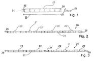
- FIGS. 1 to 3 show a floor covering 20 consisting of individual interconnected floor segments 22, which consist of a resistant material such as steel, aluminum or plastic.
- the floor covering 20 formed from floor segments 22 has a useful surface 21 and a support surface 23 facing a substrate, which in the embodiment shown are both corrugated or slightly profiled.
- the bottom segments 22 are designed as a hollow body with vertically extending support webs.
- the floor segments 22 have along side end-mounted claws 30 and arranged on the other side double hooks 32 which are inserted into the claws 30 of the adjacent bottom segment 22.
- the floor segments 22 are connected to one another either directly or via connecting elements 24.
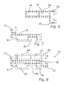
- the individual floor segments 22 preferably have a length L of about 3 m (see. Fig. 4 ) and a width B of about 0.5 m, preferably 0.53 m.
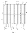
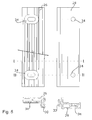
- FIGS. 2 and 3 illustrate the laying of floor segments 22 to a series, wherein after four floor segments 22, a connecting element 24 is provided.
- the connecting element 24 serves not only the connection of the series lying floor segments 22, but serves primarily the frontal connection of two adjacent rows of ground segments 22nd
- Fig. 4 illustrates this laying principle in a highly simplified representation from above. Shown are two rows of floor segments 22, which are connected to each other via claws 30 and double hooks 32. Between groups of four floor segments 22, connecting elements 24 are provided instead of the claws 30 / double hook 32 connection.
- the two rows of floor segments 22 are arranged such that the connecting elements 24 of the two rows are each frontally adjacent to each other. Connectors 40 extend into the adjacent connectors 24, are bolted, thus holding the two rows together.
- FIGS. 5 to 8 show the connecting element 24, which can also be made of a resistant material such as steel, aluminum or plastic, in section and from above ( Fig. 5 ).
- the sectional views correspond to the section line
- the connecting element 24 consists in this embodiment of a first sub-element 26 and a second sub-element 28.
- the first sub-element 26 has a claw 30 which corresponds to the claw 30 of a bottom segment 22 and via which it is connectable to a double hook 32 of a bottom segment 22.
- the second sub-element 28 accordingly has a double hook 32, which is connectable to a claw 30 of a bottom segment 22.
- the two sub-elements 26, 28 are seen in cross-section partially above one another and together form approximately the same height H as the bottom segments 22 (see. Fig. 2 ).
- the sub-elements 26, 28 each have hollow chambers 44, which leads to a relatively low weight. From the FIGS. 6 to 8 It is clear that in the assembled state of the sub-elements 26, 28, a connecting channel 38 is formed, in which a connector 40 can be inserted (see also Fig. 11 ). Furthermore, a nut channel 46 can be seen, in which a nut 37 of a connecting means 35, 37 is inserted and held in this. The nut 37 and the nut channel 46 have such dimensions that the nut 37 is rotationally held in the nut channel 46, which facilitates the assembly of the compound.
- FIGS. 9 to 11 show a sectional view according to the section line II-II Fig. 5 , Through connecting openings 34, a connecting means 35, 37, preferably a screw 35 is inserted and connected to the nut 37. Furthermore, it can also be seen that the connection opening 34 of the first subelement 26 ultimately by opening the hollow chamber 44 is formed.
- the upper, the useful surface 21 facing side of the hollow chamber 44 has for this purpose a first opening 48 which is designed as a slot and in their dimensions, the lower, the second sub-element 28 facing the second opening 50 of the hollow chamber 44 exceeds.
- the first opening 50 therefore has larger dimensions, because in addition to a screw head 52 and a nut, not shown, a Be fastening tool for tightening and loosening the screw 35 must be insertable.
- the second opening 50 of the first sub-element 26 is preferably designed as a slot, whereby the two sub-elements 26,28 shifted by a certain amount against each other and still can be connected (see also Fig. 5 ).
- the sub-elements 26, 28 are firmly connected to each other, wherein the connecting means 36 is disposed completely within the connecting element 24 ( FIG. 8 ). It can also be seen that as much material as possible is enclosed between the nut 37 and the screw head 52.
- a column S forms, which gives the connection stability, in particular against buckling and swiveling forces, upwards and downwards in the direction of the useful surface 21 or the bearing surface 23.
- FIGS. 12 and 13 illustrate the arrangement and function of the connector 40.
- the connector 40 is preferably formed as an elongate tab, each having at their free ends connecting openings 34 which are insertable between the sub-elements 26, 28, that the connecting means 35,37 through all the connection openings 34th is feasible.
- the connecting means 36 thus connects the sub-elements 26, 28 with each other, but it also holds the connector 40 between the sub-elements 26, 28.
- the connector 40 thus serves the frontal connection of two juxtaposed fasteners 24.
- At least one connection opening 34 of the connector 40 is a slot executed.
- the width of the connector is less than the width of the connection channel 38 to allow pivoting of the connector 40 within the connection channel 38.
- the connector 40 is designed waisted, which is indicated by the dashed line in Fig. 13 is indicated. The waist allows a further offset of the two connected fasteners 24 to each other.
Landscapes
- Engineering & Computer Science (AREA)
- Architecture (AREA)
- Civil Engineering (AREA)
- Structural Engineering (AREA)
- Floor Finish (AREA)
Description
- Die vorliegende Erfindung betrifft ein Verbindungselement für Bodensegmente eines Bodenbelags.
- Bodenbeläge werden vielfach als Bodenschutzsysteme eingesetzt, sie dienen oftmals aber auch der Schaffung einer möglichst, gleichmäßigen, ebenen Fläche und sorgen damit auch für eine gleichmäßige Lastverteilung. Sie eignen sich als Transportwege oder Bühnenunterbau bei Veranstaltungen, Baustellenzufahrten, Wegverbreiterungen, Montageplattformen und Lagerflächen. Sie können aber auch zum Schutz sensibler Oberflächen, wie Kopfsteinpflaster oder auf Tartanbahnen in Stadien, vor allem aber auf Rasenflächen wie Fußballfeldern und ähnlichem eingesetzt werden. Für diesen Zweck sind oftmals weitere Schutzmaßnahmen, wie ein Unterlegen des Bodenbelags mit Gummimatten oder Textilien sinnvoll.
- Bodenbeläge dieser Art bestehen üblicherweise aus einzelnen Bodensegmenten, die mit Hilfe von Verbindungsmitteln vor Ort miteinander verbunden werden. Die Bodensegmente weisen zu diesem Zweck meist durchgängige Öffnungen auf, die entlang der Längs-und/oder Querseiten angeordnet sind. Bei der Verlegung vor Ort werden die Bodensegmente zunächst aneinander gelegt, geeignete Laschen, die endseitig ebenfalls Öffnungen aufweisen, werden auf die Öffnungen zweier Bodensegmenten aufgelegt, Verbindungsmittel vorzugsweise Schrauben durch die Öffnungen hindurchgesteckt und die Laschen mit den Bodensegmenten verschraubt, die dann untereinander verbunden sind.
- Nachteilig bei dieser Art der Verbindung ist, dass die Laschen und ggf. auch die Verbindungsmittel gegenüber dem neu geschaffenen Untergrund vorstehen. Es besteht die Gefahr, dass Personen über diese stolpern oder Fahrzeuge bzw. deren Reifen oder Ketten beim Überfahren beschädigt werden.
- Ein weiterer wesentlicher Nachteil derartiger Systeme ist das hohe Gewicht der Bodensegmente. Da oftmals große Flächen, wie Fußballfelder oder ähnliches, belegt werden, ist eine entsprechend große Anzahl an Bodensegmenten anzuliefern und vor Ort zu bewegen. Da Bodensegmente in vielen Fällen einer Radlast von bis zu 6 Tonnen standhalten müssen, sind sie entsprechend massiv ausgeführt, sie sind aus Vollmaterial gefertigt oder weisen bei einer Ausführung als Hohlkörper große Wandstärken auf.
- Ein Verbindungselement mit den Merkmalen des Oberbegriffs des Anspruchs 1 ist aus
US3175476 bekannt. - Die Aufgabe der vorliegenden Erfindung besteht darin, ein Verbindungselement für einen Bodenbelag zu schaffen, dass eine zuverlässige Verbindung von Bodensegmenten ermög-licht. Dabei soll die durch den Bodenbelag neu geschaffene Fläche möglichst eben sein und keine vorstehenden Elemente aufweisen. Weiterhin soll das Verlegen bzw. Montieren des Bodenbelags und der Verbindungsmittel schnell und einfach möglich sein. Das Verbindungselement soll kostengünstig herstellbar sein und ein möglichst geringes Gewicht aufweisen.
- Erfindungsgemäß wird die Aufgabe durch ein Verbindungselement, bestehend aus einem ersten Teilelement und einem zweiten Teilelement, die jeweils Verbindungsöffnungen aufweisen, über die sie mit einem Verbindungsmittel miteinander verbindbar sind und die im zusammengesetzten Zustand einen Verbindungskanal ausbilden, in dem ein Verbinder angeordnet werden kann, der ebenfalls eine Verbindungsöffnung für das Verbindungsmittel aufweist, wobei der Verbinder aus dem Verbindungselement derart seitlich herausragt, dass er in einen Verbindungskanal eines benachbarten Verbindungselementes einführbar ist und sich dort ebenfalls ein Verbindungsmittel durch eine zweite Verbindungsöffnung erstrecken kann, so dass zwei nebeneinander angeordnete Verbindungselemente über den Verbinder miteinander verbindbar sind, wobei das Verbindungsmittel derartige Abmessungen aufweist, dass es nicht über eine Nutzfläche des Bodenbelags vorsteht, gelöst.
- Ein wesentlicher Vorteil der Erfindung besteht darin, dass mit dem Bodenbelag eine ebene Fläche geschaffen wird, aus der keine Verbindungsmittel, Laschen oder ähnliches vorstehen. Hierzu weisen die Teilelemente Öffnungen auf, in die die Verbindungsmittel, vorzugsweise Schrauben, versenkbar sind, Schraubenkopf und Schraubenmutter stehen nicht gegenüber dem Verbindungselement und der Nutzfläche über. Die Verbinder, die notwendig sind, um Bodensegmente auch in Querrichtung miteinander zu verbinden, sind innerhalb der Verbindungselemente angeordnet, die die Bodensegmente in Längsrichtung verbinden. Die Verbindungsmittel, die durch die Verbindungsöffnungen der Teilelemente und des Verbinders geschoben werden, verbinden also gleichzeitig den Verbinder mit den Verbindungselementen, als auch die Teilelemente eines Verbindungselementes miteinander. Im Gegensatz zu der im Stand der Technik üblichen Befestigung der Verbinder auf der Oberseite des Bodenbelags sind die erfindungsgemäß innerhalb des Verbindungselementes angeordneten Verbinder vorteilhafterweise besser gegen Verschmutzung und Witterungseinflüsse geschützt.
- Ein weiterer wesentlicher Vorteil der Erfindung besteht darin, dass sowohl das Verbindungselement als auch die Bodensegmente selbst nur ein relativ geringes Eigengewicht aufweisen. Das Verbindungselement ist im Wesentlichen als Hohlkörper ausgebildet, wodurch bereits eine erhebliche Gewichtsreuzierung erreicht wird.
- Erfindungsgemäß sind die Teilsegmente derart ausgeführt, dass sich zwischen dem Schraubenkopf und der Schraubenmutter möglichst viel Material der Teilsegmente befindet. Mit anderen Worten sind der Schraubenkopf und die Schraubenmutter maximal voneinander beabstandet, nutzen also die Gesamthöhe des Verbindungselementes aus. Dies führt dazu, dass die Verbindung auch gegenüber Knick- bzw. Schwenkbewegungen sehr widerstandsfähig ist. Solche Kräfte können zum Beispiel dann auftreten, wenn auf einem ersten Bodensegment ein Fahrzeug steht und ein mit diesem Bodensegment verbundenes zweites Bodensegment versehentlich angehoben (zum Beispiel von einem Gabelstapler) oder durch ein zweites Fahrzeug beispielsweise in eine Bodensenke gedrückt wird. In beiden Fällen wird die Verbindung im Bereich der Schrauben aufgrund der Hebelkräfte durch die Bewegung der Bodensegmente nach oben oder unten stark beansprucht und könnte sich bei unzureichender Ausführung des Verbindungselementes lösen. Das erfindungsgemäße Verbindungselement verhindert durch Ableiten der Kräfte über das Material zwischen Schraubenkopf und der Schraubenmutter und die Rahmenkonstruktion der Teilsegmente in die sich anschließenden Bodensegmente eine zu starke Knick- oder Schwenkbewegung innerhalb des Verbindungselementes.
- Zumindest eine Verbindungsöffnung der Teilelemente für die Aufnahme der Verbindungsmittels ist vorteilhafterweise als Langloch ausgeführt, um eine gewisse Bewegung der Verbindung in Querrichtung zuzulassen. Das gleiche gilt für den Verbinder, auch bei diesem ist zumindest eine Verbindungsöffnung als Langloch ausgeführt, um die gewünschte Toleranz auch in Längsrichtung zu erreichen. Hierdurch kann auf Materialtoleranzen, mechanische Verformungen der Bodensegmente und Verbindungselemente oder unebene und ungleichmäßige Böden vor Ort bei der Verlegung des Bodens schnell und einfach reagiert werden.
- In einer besonders vorteilhaften Ausführungsvariante weist der Verbinder eine geringere Breite als der Verbindungskanal auf, wodurch er innerhalb des Verbindungskanals um die jeweils endseitig angeordneten Verbindungsmittel um einige Grad, nämlich bis zum seitlichen Anschlag des Verbinders an der Verbindungskanalwand im Bereich des offenen Endes des Verbindungskanals verschwenkbar ist, was das Montieren und Verlegen vor Ort weiter erleichtert. Die Verschwenkbarkeit der Verbinder bewirkt, dass die Bodensegmente in gewissen Rahmen versetzt zueinander angeordnet sein können. Der Grad der möglichen Schwenkbewegung innerhalb des Verbindungskanals kann durch eine Taillierung des Verbinders erfindungsgemäß weiter erhöht werden. Die Taillierung bewirkt, dass der Anschlag des Verbinders an der Verbindungskanalwand erst später erfolgt. Weiterhin hat eine solche Taillierung auch den Vorteil einer erheblichen Gewichtsreduzierung.
- Die Verbinder weisen vorzugsweise eine Höhe auf, die die Höhe des Verbindungskanals um einen gewissen Betrag, beispielsweise um 0,1 mm bei einer Höhe des Verbindungskanals von etwa 4 mm, übersteigt. Der Überstand führt beim Zusammenfügen und Verschrauben der Teilelemente zu einer Klemmwirkung, so dass die beiden Teilelemente fest miteinander verbunden sind und eine unerwünschte Geräuschentwicklung aufgrund von Schwingungen oder Bewegungen der Verbinder innerhalb der Verbindungskanäle vermieden wird.
- Die in das Verbindungselement eingelassenen Verbindungsmittel können auf ihrer Oberseite durch eine Abdeckung abgedeckt werden, um einen durchgängigen Bodenbelag ohne Öffnungen zu schaffen. Im Gegensatz zu bekannten Bodenbelägen ist die Nutzung des erfindungsgemäßen Bodenbelags auch dadurch für eine Vielzahl weiterer Verwendungsmöglichkeiten denkbar. Hierzu gehört u.a. die Verwendung als Sportbodenbelag oder für ähnliche Veranstaltungen, bei denen eine Bodenfläche ohne vorstehende Elemente oder sogar ohne Öffnungen notwendig ist. Der mit Hilfe der erfindungsgemäßen Verbindungselemente geschaffene Boden entspricht im Gegensatz zu bisher bekannten Böden dieser Art den Anforderungen der Versammlungsstättenverordnung im Sinne des EU-Rechtes, da er keine unzulässigen Stolperfallen aufweist.
- Die erfindungsgemäßen Verbindungselemente weisen an ihren Längsseiten weiterhin Befestigungsmittel für eine Befestigung mit den zu verbindenden Bodensegmenten auf. Diese Befestigungsmittel können grundsätzlich beliebig ausgeführt sein, lösbare Verbindungen haben sich aber als vorteilhaft erwiesen. Das erste Teilelement weist in einer vorteilhaften Ausführungsvariante eine Art Klaue auf, das zweite Teilsegment einen damit kompatiblen Doppelhaken. Die Bodensegmente weisen ebenfalls auf einer Seite die Klaue und auf der anderen Seite den Doppelhaken auf.
- Somit kann je nach Anforderung vor Ort entschieden werden, ob die Bodensegmente über ihre Klauen/Doppelhakenverbindung unmittelbar miteinander verbunden werden oder ob ein Bodensegment über ein Verbindungsmittel mit dem nächsten Bodensegment verbunden werden soll. Die Verbindung von Bodensegmenten über Verbindungsmittel ist dabei deshalb notwendig, um Reihen aus Bodensegmenten stirnseitig miteinander verbinden zu können.
- Es hat sich als vorteilhaft erwiesen, wenn zwei oder mehr, vorzugsweise vier Bodensegmente über die erfindungsgemäßen Befestigungsmittel unmittelbar zu einem Panel miteinander verbunden werden, wobei eine Vielzahl solcher Panels wiederum über erfindungsgemäße Verbindungselemente zu einer beliebig langen Reihe miteinander verbindbar sind. Über die Verbinder der einzelnen Verbindungselemente ist eine solche Reihe mit einer benachbarten Reihe verbindbar, so dass die beiden verbundenen Reihen nahezu spaltfrei nebeneinander liegen.
- Für die Verwendung als Stadion-Bodenbelag haben sich Bodensegmente als geeignet erwiesen, die etwa eine Länge von 3 Meter und eine Breite von etwa 0,5 m aufweisen. Ein Panel bestehend aus vier Bodensegmenten weist somit eine Gesamtfläche von etwa 3 x 2 Meter auf und ist problemlos in einem geschlossenen LKW transportierbar. Vor Ort müssen die so vorgefertigten Panels dann nur noch über die erfindungsgemäßen Verbindungselemente miteinander verbunden werden.
- Erfindungsgemäß sind Bodensegmente, die für eine Radlast von bis zu 6 Tonnen ausgelegt sind, aus Aluminium gefertigt, etwa 5 cm hoch und zur Gewichtseinsparung als Hohlkörper ausgebildet. Um dennoch eine ausreichende Statik aufzuweisen, sind innerhalb der Hohlkörper Stützstege vorgesehen, die die Unterseite mit der Oberseite verbinden und somit die begehbare Oberseite stützen. Bei einer Gesamtbreite eines Bodensegments von etwa 0,5 m weisen die Stützstege einen Abstand von etwa 6 cm zueinander auf, wodurch sich 8 Kammern innerhalb des Bodensegments ausbilden.
- Erfindungsgemäß beträgt die Wandstärke der Oberseite 3,5 mm, wo hingegen die Wandstärke der Unterseite nur 3 mm aufweist. Die Wandstärke der Stützstege beträgt ebenfalls nur etwa 3 mm. Diese erfindungsgemäße Ausbildung mit relativ wenigen Stützstegen und nur geringer Wandstärke ist wesentlich leichter als vergleichbare bekannte Bodensegmente. Die Hohlkammerausführung und die Verwendung der Stützstege ermöglicht die deutlich geringere Wandstärke der Oberseite und Unterseite. Die etwas stärkere Wandstärke der Oberseite verhindert wirksam Einstanzungen, beispielsweise durch liegen gebliebene Nägel oder ähnliches. Ein erfindungsgemäßes aus vier Bodensegmenten zusammengesetztes Panel mit zwei seitlich angeordneten Teilelementen wiegt nur etwa 175 kg, was eine deutliche Verbesserung zu bekannten Böden darstellt. Ein solches Panel ist von vier Personen problemlos tragbar und kann vor Ort leicht verlegt werden. Trotzdem ist das erfindungsgemäße Bodensegment ausreichend dimensioniert, um den geforderten Radlasten von bis zu 6 t standzuhalten.
- Anhand der nachfolgenden Figuren wird die Erfindung näher erläutert. Es zeigen:
- Fig. 1 bis 3:
- einen Bodenbelag mit erfindungsgemäßen Verbindungselementen im Schnitt,
- Fig. 4:
- Prinzipskizze eines Bodenbelags von oben,
-
Fig. 5 : zwei Teilelemente im Schnitt und von oben,Fig. 6 : ein erstes Teilelement eines Verbindungselements im Schnitt gemäß I-I inFig. 5 ,Fig. 7 : ein zweites Teilelement eines Verbindungselements im Schnitt gemäß I-I inFig. 5 ,Fig. 8 : die beiden Teilelemente ausFigur 6 und Figur 7 im zusammengesetzten Zustand mit einem Verbindungsmittel.Fig. 9 bis 11 : Darstellungen der Teilelemente bzw. des Verbindungselementes im Schnitt gemäß II-II inFig. 5 ,Fig. 12 : einen erfindungsgemäßen Verbinder,Fig. 13 : einen erfindungsgemäßen Verbinder, eingesetzt in zwei Teilelemente. - Die
Figuren 1 bis 3 zeigen einen Bodenbelag 20, bestehend aus einzelnen miteinander verbundenen Bodensegmenten 22, die aus einem widerstandsfähigen Material wie Stahl, Aluminium oder Kunststoff bestehen. Der aus Bodensegmenten 22 gebildete Bodenbelag 20 weist eine Nutzfläche 21 und eine einem Untergrund zugewandte Auflagefläche 23 auf, die im gezeigten Ausführungsbeispiel beide geriffelt bzw. leicht profiliert ausgeführt sind. Die Bodensegmente 22 sind als Hohlkörper mit sich darin vertikal erstreckenden Stützstegen ausgeführt. - Die Bodensegmente 22 weisen längsseits endseitig angeordneter Klauen 30 und auf der anderen Seite angeordnete Doppelhaken 32 auf, die in die Klauen 30 des benachbarten Bodensegments 22 einschiebbar sind. Die Bodensegmente 22 sind entweder unmittelbar miteinander oder über Verbindungselemente 24 miteinander verbunden.
- Die einzelnen Bodensegmente 22 weisen vorzugsweise eine Länge L von etwa 3 m (vgl.
Fig. 4 ) und eine Breite B von etwa 0,5 m, vorzugsweise von 0,53 m auf. - Die
Figuren 2 und 3 verdeutlichen die Verlegung von Bodensegmenten 22 zu einer Reihe, wobei nach vier Bodensegmenten 22 ein Verbindungselement 24 vorgesehen ist. Das Verbindungselement 24 dient dabei nicht nur der Verbindung der in Reihe liegenden Bodensegmente 22, sondern dient in erster Linie der stirnseitigen Verbindung zweier nebeneinander liegender Reihen von Bodensegmenten 22.Fig. 4 verdeutlicht dieses Verlegeprinzip in einer stark vereinfachten Darstellung von oben. Gezeigt sind zwei Reihen Bodensegmente 22, die jeweils über Klauen 30 und Doppelhaken 32 miteinander verbunden sind. Zwischen Gruppen von vier Bodensegmente 22 sind anstelle der Klauen 30/Doppelhaken 32-Verbindung Verbindungselemente 24 vorgesehen. Die beiden Reihen aus Bodensegmenten 22 sind derart angeordnet, dass die Verbindungselemente 24 der beiden Reihen jeweils stirnseitig aneinander liegen. Verbinder 40 erstrecken sich in die benachbarten Verbindungselemente 24, sind verschraubt und halten somit die beiden Reihen aneinander. - Die
Figuren 5 bis 8 zeigen das Verbindungselement 24, das ebenfalls aus einem widerstandsfähigen Material wie Stahl, Aluminium oder Kunststoff bestehen kann, im Schnitt und von oben (Fig. 5 ). Die Schnittdarstellungen entsprechen der Schnittlinie - I-I in
Fig. 5 . Das Verbindungselement 24 besteht in dieser Ausführungsvariante aus einem ersten Teilelement 26 und einem zweiten Teilelement 28. Das erste Teilelement 26 weist eine Klaue 30 auf, die der Klaue 30 eines Bodensegmentes 22 entspricht und über die es mit einem Doppelhaken 32 eines Bodensegments 22 verbindbar ist. Das zweite Teilelement 28 weist entsprechend einen Doppelhaken 32 auf, der mit einer Klaue 30 eines Bodensegments 22 verbindbar ist. Die beiden Teilelemente 26, 28 liegen im Querschnitt gesehen bereichsweise übereinander und bilden zusammen etwa die gleiche Höhe H wie die Bodensegmente 22 aus (vgl.Fig. 2 ). - Die Teilelemente 26, 28 weisen jeweils Hohlkammern 44 auf, was zu einem relativ geringen Gewicht führt. Aus den
Figuren 6 bis 8 wird deutlich, dass sich im zusammengesetzten Zustand der Teilelemente 26, 28 ein Verbindungskanal 38 ausbildet, in den ein Verbinder 40 eingefügt werden kann (vergl. auchFig. 11 ). Weiterhin ist ein Mutterkanal 46 erkennbar, in den eine Mutter 37 eines Verbindungsmittels 35, 37 einführbar und in diesem gehalten ist. Die Mutter 37 und der Mutterkanal 46 weisen derartige Abmessungen auf, dass die Mutter 37 verdrehfest in dem Mutterkanal 46 gehalten ist, was die Montage der Verbindung erleichtert. - Die
Figuren 9 bis 11 zeigen eine Schnittdarstellung gemäß der Schnittlinie II-II ausFig. 5 . Durch Verbindungsöffnungen 34 kann ein Verbindungsmittel 35, 37, vorzugsweise eine Schraube 35 eingeführt und mit der mit Mutter 37 verbunden werden. Weiterhin ist auch erkennbar, dass die Verbindungsöffnung 34 des ersten Teilelementes 26 letztendlich durch Öffnen der Hohlkammer 44 entsteht. Die obere, der Nutzfläche 21 zugewandte Seite der Hohlkammer 44 weist zu diesem Zweck eine erste Öffnung 48 auf, die als Langloch ausgeführt ist und in ihren Abmessungen die untere, dem zweiten Teilelement 28 zugewandet zweite Öffnung 50 der Hohlkammer 44 übersteigt. Die erste Öffnung 50 weist deshalb größere Abmessungen auf, weil in diese neben einem Schraubenkopf 52 auch eine nicht gezeigte Nuss eines Be festigungswerkzeugs zum Anziehen und Lösen der Schraube 35 einführbar sein muss. Auch die zweite Öffnung 50 des ersten Teilelementes 26 ist vorzugsweise als Langloch ausgeführt, wodurch die beiden Teilelemente 26,28 um einen gewissen Betrag gegeneinander verschoben und trotzdem verbunden werden können (vgl. auchFig. 5 ). - Die Teilelemente 26, 28 sind fest miteinander verbindbar, wobei das Verbindungsmittel 36 vollständig innerhalb des Verbindungselements 24 angeordnet ist (
Figur 8 ). Erkennbar ist auch, dass zwischen der Mutter 37 und dem Schraubenkopf 52 möglichst viel Material eingeschlossen ist. Es bildet sich eine Säule S aus, die der Verbindung Stabilität insbesondere gegen Knick- und Verschwenkkräfte nach oben und unten in Richtung der Nutzfläche 21 bzw. der Auflagefläche 23 gibt. - Die
Figuren 12 und 13 verdeutlichen die Anordnung und Funktion des Verbinders 40. Der Verbinder 40 ist vorzugsweise als längliche Lasche ausgebildet, die jeweils an ihren freien Enden Verbindungsöffnungen 34 aufweist, die derart zwischen die Teilelemente 26, 28 einführbar sind, dass das Verbindungsmittel 35,37 durch alle Verbindungsöffnungen 34 durchführbar ist. Das Verbindungsmittel 36 verbindet also die Teilelemente 26, 28 miteinander, es hält aber auch den Verbinder 40 zwischen den Teilelementen 26, 28. Der Verbinder 40 dient somit der stirnseitigen Verbindung zweier nebeneinander angeordneter Verbindungselemente 24. Zumindest eine Verbindungsöffnung 34 des Verbinders 40 ist als Langloch ausgeführt. Die Breite des Verbinders ist geringer als die Breite des Verbindungskanals 38, um ein Verschwenken des Verbinders 40 innerhalb des Verbindungskanals 38 zu ermöglichen. In einer bevorzugten erfindungsgemäßen Ausführungsvariante ist der Verbinder 40 tailliert ausgeführt, was durch die gestrichelte Linie inFig. 13 angedeutet ist. Die Taillierung erlaubt einen noch weiteren Versatz der beiden verbundenen Verbindungselemente 24 zueinander. - Die Erfindung ist durch die Ansprüche definiert und ist nicht auf das dargestellte Ausführungsbeispiel beschränkt, sondern umfasst auch weitere, gleichwirkende Ausführungsformen.
Claims (10)
- Verbindungselement (24) für einen Bodenbelag (20), bestehend aus einem ersten Teilelement (26) und einem zweiten Teilelement (28), die jeweils Verbindungsöffnungen (34) aufweisen, über die sie mit einem Verbindungsmittel (35,37) miteinander verbindbar sind und die im zusammengesetzten Zustand einen Verbindungskanal (38) ausbilden, in dem ein Verbinder (40) angeordnet ist, wobei das Verbindungsmittel (35,37) derartige Abmessungen aufweist, dass es nicht über eine Nutzfläche (21) des Bodenbelags (20) vorsteht.dadurch gekennzeichnet, dass der Verbinder ebenfalls eine Verbindungsöffnung (34) für das Verbindungsmittel (35,37) aufweist, und dass der Verbinder (40) aus dem Verbindungselement (24) derart seitlich herausragt, dass er in einen Verbindungskanal (38) eines benachbarten Verbindungselementes (24) einführbar ist und sich dort ebenfalls ein Verbindungsmittel (36) durch eine zweite Verbindungsöffnung (34) erstrecken kann, so dass zwei nebeneinander angeordnete Verbindungselemente (24) über den Verbinder (40) miteinander verbindbar sind.
- Verbindungselement (24) nach Anspruch 1, dadurch gekennzeichnet, dass die Teilelemente (26, 28) Befestigungsmittel zur Befestigung an Bodensegmenten (22) des Bodenbelags (20) aufweisen.
- Verbindungselement (24) nach Anspruch 2, dadurch gekennzeichnet, dass das erste Teilelement (26) als Befestigungsmittel eine Klaue (30) und das zweite Teilelement (28) als Befestigungsmittel einen Doppelhaken (32) aufweist, die mit jeweils korrespondierenden gleichartigen Befestigungsmittel der Bodensegmente (22) verbindbar sind.
- Verbindungselement (24) nach einem der Ansprüche 1 bis 3, dadurch gekennzeichnet, dass die Teilelemente (26, 28) Hohlkammern (44) aufweisen.
- Verbindungselement (24) nach Anspruch 4, dadurch gekennzeichnet, dass die Verbindungsöffnung (34) des ersten Teilelementes (26) durch Öffnen der Hohlkammer (44) gebildet ist, wobei eine der Nutzfläche (21) zugewandte Seite der Hohlkammer (44) eine erste Öffnung (48) aufweist, die als Langloch ausgeführt ist und in ihren Abmessungen eine untere, dem zweiten Teilelement (28) zugewandet zweite Öffnung (50) der Hohlkammer (44), die ebenfalls als Langloch ausgeführt ist, übersteigt.
- Verbindungselement (24) nach einem der Ansprüche 1 bis 5, dadurch gekennzeichnet, dass der Verbinder (40) als längliche Lasche ausgebildet ist, dessen Breite geringer als die Breite des Verbindungskanals (38) ist.
- Verbindungselement (24) nach einem der Ansprüche 1 bis 6, dadurch gekennzeichnet, dass der Verbinder (40) als längliche Lasche ausgebildet ist, dessen Höhe die Höhe des Verbindungskanals (38) übersteigt.
- Verbindungselement (24) nach einem der Ansprüche 1 bis 7, gekennzeichnet durch eine Verbindung mit Bodensegmenten (22), die als Hohlkörper mit sich darin vertikal erstreckenden Stützstegen ausgeführt sind.
- Verbindungselement (24) nach Anspruch 8, dadurch gekennzeichnet, dass die Bodensegmente (22) eine Länge (L) von etwa 3 m, eine Breite (B) von etwa 0,5 m und eine Höhe (H) von etwa 0,05 m lag aufweisen.
- Verbindungselement (24) nach Anspruch 8 oder 9, dadurch gekennzeichnet, dass die Bodensegmente (22) aus Aluminium bestehen und eine Wandstärke von etwa 0,003 m aufweisen.
Priority Applications (1)
| Application Number | Priority Date | Filing Date | Title |
|---|---|---|---|
| PL08100964T PL1950349T3 (pl) | 2007-01-25 | 2008-01-25 | Wykładzina podłogowa |
Applications Claiming Priority (1)
| Application Number | Priority Date | Filing Date | Title |
|---|---|---|---|
| DE102007004662 | 2007-01-25 |
Publications (3)
| Publication Number | Publication Date |
|---|---|
| EP1950349A2 EP1950349A2 (de) | 2008-07-30 |
| EP1950349A3 EP1950349A3 (de) | 2013-11-13 |
| EP1950349B1 true EP1950349B1 (de) | 2015-03-11 |
Family
ID=39315057
Family Applications (1)
| Application Number | Title | Priority Date | Filing Date |
|---|---|---|---|
| EP08100964.9A Active EP1950349B1 (de) | 2007-01-25 | 2008-01-25 | Bodenbelag |
Country Status (3)
| Country | Link |
|---|---|
| EP (1) | EP1950349B1 (de) |
| ES (1) | ES2536511T3 (de) |
| PL (1) | PL1950349T3 (de) |
Cited By (1)
| Publication number | Priority date | Publication date | Assignee | Title |
|---|---|---|---|---|
| DE202021104073U1 (de) | 2021-07-02 | 2021-08-17 | Cteam Consulting & Anlagenbau Gmbh | Modularer Bodenbelag |
Families Citing this family (1)
| Publication number | Priority date | Publication date | Assignee | Title |
|---|---|---|---|---|
| PT3401441T (pt) * | 2017-05-08 | 2020-09-04 | Roadrunner Concert Service Nv | Pavimento modular concebido para suportar veículos e multidões numa subsuperfície irregular ou mole, e prancha, método de instalação e método de produção associados |
Family Cites Families (3)
| Publication number | Priority date | Publication date | Assignee | Title |
|---|---|---|---|---|
| US3175476A (en) * | 1963-04-29 | 1965-03-30 | Fenestra Inc | Locking bar for auxiliary landing mat |
| GB0212382D0 (en) * | 2002-05-29 | 2002-07-10 | Fergus Johnathan A | Interconnecting track sections of multi-sectional trackway |
| EP1699978A1 (de) * | 2003-12-16 | 2006-09-13 | Alvaro Savoldi | Pflastervorrichtung für militarische zwecke und/oder landebahnen |
-
2008
- 2008-01-25 EP EP08100964.9A patent/EP1950349B1/de active Active
- 2008-01-25 ES ES08100964.9T patent/ES2536511T3/es active Active
- 2008-01-25 PL PL08100964T patent/PL1950349T3/pl unknown
Cited By (4)
| Publication number | Priority date | Publication date | Assignee | Title |
|---|---|---|---|---|
| DE202021104073U1 (de) | 2021-07-02 | 2021-08-17 | Cteam Consulting & Anlagenbau Gmbh | Modularer Bodenbelag |
| EP4112814A1 (de) | 2021-07-02 | 2023-01-04 | Cteam Consulting & Anlagenbau GmbH | Modularer bodenbelag |
| DE102021117145A1 (de) | 2021-07-02 | 2023-01-05 | Cteam Consulting & Anlagenbau Gmbh | Modularer Bodenbelag |
| EP4502270A2 (de) | 2021-07-02 | 2025-02-05 | Cteam Consulting & Anlagenbau GmbH | Modularer bodenbelag |
Also Published As
| Publication number | Publication date |
|---|---|
| EP1950349A2 (de) | 2008-07-30 |
| EP1950349A3 (de) | 2013-11-13 |
| ES2536511T3 (es) | 2015-05-26 |
| PL1950349T3 (pl) | 2015-08-31 |
Similar Documents
| Publication | Publication Date | Title |
|---|---|---|
| DE102008006251B4 (de) | Verbindungselement für einen Bodenbelag | |
| DE202016105226U1 (de) | Carport | |
| EP3710651A1 (de) | Parkplattform für ein kraftfahrzeug | |
| EP2712962B1 (de) | Mobile Schutzwand | |
| DE69915770T2 (de) | Bodensystem mit Deflexurejustagemöglichkeit | |
| DE2803892A1 (de) | Bodenbelagsplatte und damit hergestellter bodenbelag | |
| DE102013108470A1 (de) | Unterkonstruktion für einen Bodenbelag | |
| DE102008003281A1 (de) | Flächenelement | |
| EP2281959B1 (de) | Kragplattenanschlusselement | |
| EP1950349B1 (de) | Bodenbelag | |
| EP2522928B1 (de) | Vorrichtung für die Montage von Aufbauten auf einer flachen Ebene oder einer Ebene mit geringer Neigung | |
| DE102025000917A1 (de) | Vorrichtung zum Verspannen von Bauplatten | |
| DE102018217108A1 (de) | Dachkonstruktion für carports mit pv-modulen sowie ein verfahren zum montieren eines derartigen carports | |
| EP1197611A1 (de) | Fussboden-Fertigplatte zur Bildung eines demontierbaren Fussbodens | |
| DE202007012020U1 (de) | Trägersystem für Photovoltaikelemente | |
| DE102007040735A1 (de) | Trägersystem für Photovoltaikelemente | |
| EP3430304B1 (de) | Sockelelement zur lastabtragenden aufnahme eines gehäusemoduls eines selbstbedienungsautomaten | |
| EP4339395A1 (de) | Terrassenaufbau mit sichtprofilen | |
| AT507117B1 (de) | Carport | |
| AT522974B1 (de) | Platten zur bildung eines kraftaufnehmenden oberflächenbelags | |
| EP2425069B1 (de) | Nivellierhilfe für holz-/balken-unterkonstruktionen insbesondere von balkon- und terrassenabdeckungen | |
| DE3246576C2 (de) | Fußboden für Zelt- oder dergleichen auf- und abbaubare Hallenkonstruktionen | |
| EP2915920B1 (de) | Verfahren zum verlegen von flächig begrenzten bodenbelägen | |
| DE102018119046A1 (de) | Wandelement für eine Verkehrsleit- und/oder absperrwand | |
| EP2627827B1 (de) | Modulare trägerkonstruktion |
Legal Events
| Date | Code | Title | Description |
|---|---|---|---|
| PUAI | Public reference made under article 153(3) epc to a published international application that has entered the european phase |
Free format text: ORIGINAL CODE: 0009012 |
|
| AK | Designated contracting states |
Kind code of ref document: A2 Designated state(s): AT BE BG CH CY CZ DE DK EE ES FI FR GB GR HR HU IE IS IT LI LT LU LV MC MT NL NO PL PT RO SE SI SK TR |
|
| AX | Request for extension of the european patent |
Extension state: AL BA MK |
|
| 17P | Request for examination filed |
Effective date: 20090831 |
|
| RAP1 | Party data changed (applicant data changed or rights of an application transferred) |
Owner name: EPS HOLDING GMBH |
|
| PUAL | Search report despatched |
Free format text: ORIGINAL CODE: 0009013 |
|
| AK | Designated contracting states |
Kind code of ref document: A3 Designated state(s): AT BE BG CH CY CZ DE DK EE ES FI FR GB GR HR HU IE IS IT LI LT LU LV MC MT NL NO PL PT RO SE SI SK TR |
|
| AX | Request for extension of the european patent |
Extension state: AL BA MK |
|
| RIC1 | Information provided on ipc code assigned before grant |
Ipc: E01C 9/08 20060101ALI20131009BHEP Ipc: E01C 5/00 20060101AFI20131009BHEP |
|
| AKY | No designation fees paid | ||
| REG | Reference to a national code |
Ref country code: DE Ref legal event code: R108 |
|
| REG | Reference to a national code |
Ref country code: DE Ref legal event code: R108 Ref document number: 502008012753 Country of ref document: DE Effective date: 20140716 Ref country code: DE Ref legal event code: R108 Effective date: 20140716 |
|
| RBV | Designated contracting states (corrected) |
Designated state(s): AT BE BG CH CY LI |
|
| GRAP | Despatch of communication of intention to grant a patent |
Free format text: ORIGINAL CODE: EPIDOSNIGR1 |
|
| RBV | Designated contracting states (corrected) |
Designated state(s): AT BE BG CH CY CZ LI |
|
| RBV | Designated contracting states (corrected) |
Designated state(s): AT BE BG CH CY CZ DE DK EE ES FI FR GB GR HR HU IE IS IT LI LT LU LV MC MT NL NO PL PT RO SE SI SK TR |
|
| INTG | Intention to grant announced |
Effective date: 20141009 |
|
| INTG | Intention to grant announced |
Effective date: 20141015 |
|
| GRAS | Grant fee paid |
Free format text: ORIGINAL CODE: EPIDOSNIGR3 |
|
| GRAA | (expected) grant |
Free format text: ORIGINAL CODE: 0009210 |
|
| AK | Designated contracting states |
Kind code of ref document: B1 Designated state(s): AT BE BG CH CY CZ DE DK EE ES FI FR GB GR HR HU IE IS IT LI LT LU LV MC MT NL NO PL PT RO SE SI SK TR |
|
| REG | Reference to a national code |
Ref country code: GB Ref legal event code: FG4D Free format text: NOT ENGLISH |
|
| REG | Reference to a national code |
Ref country code: CH Ref legal event code: EP |
|
| REG | Reference to a national code |
Ref country code: IE Ref legal event code: FG4D Free format text: LANGUAGE OF EP DOCUMENT: GERMAN |
|
| REG | Reference to a national code |
Ref country code: AT Ref legal event code: REF Ref document number: 715430 Country of ref document: AT Kind code of ref document: T Effective date: 20150415 |
|
| REG | Reference to a national code |
Ref country code: DE Ref legal event code: R096 Ref document number: 502008012753 Country of ref document: DE Effective date: 20150423 |
|
| REG | Reference to a national code |
Ref country code: ES Ref legal event code: FG2A Ref document number: 2536511 Country of ref document: ES Kind code of ref document: T3 Effective date: 20150526 |
|
| REG | Reference to a national code |
Ref country code: NL Ref legal event code: T3 |
|
| PG25 | Lapsed in a contracting state [announced via postgrant information from national office to epo] |
Ref country code: SE Free format text: LAPSE BECAUSE OF FAILURE TO SUBMIT A TRANSLATION OF THE DESCRIPTION OR TO PAY THE FEE WITHIN THE PRESCRIBED TIME-LIMIT Effective date: 20150311 Ref country code: HR Free format text: LAPSE BECAUSE OF FAILURE TO SUBMIT A TRANSLATION OF THE DESCRIPTION OR TO PAY THE FEE WITHIN THE PRESCRIBED TIME-LIMIT Effective date: 20150311 Ref country code: NO Free format text: LAPSE BECAUSE OF FAILURE TO SUBMIT A TRANSLATION OF THE DESCRIPTION OR TO PAY THE FEE WITHIN THE PRESCRIBED TIME-LIMIT Effective date: 20150611 Ref country code: FI Free format text: LAPSE BECAUSE OF FAILURE TO SUBMIT A TRANSLATION OF THE DESCRIPTION OR TO PAY THE FEE WITHIN THE PRESCRIBED TIME-LIMIT Effective date: 20150311 Ref country code: LT Free format text: LAPSE BECAUSE OF FAILURE TO SUBMIT A TRANSLATION OF THE DESCRIPTION OR TO PAY THE FEE WITHIN THE PRESCRIBED TIME-LIMIT Effective date: 20150311 |
|
| REG | Reference to a national code |
Ref country code: LT Ref legal event code: MG4D |
|
| PG25 | Lapsed in a contracting state [announced via postgrant information from national office to epo] |
Ref country code: GR Free format text: LAPSE BECAUSE OF FAILURE TO SUBMIT A TRANSLATION OF THE DESCRIPTION OR TO PAY THE FEE WITHIN THE PRESCRIBED TIME-LIMIT Effective date: 20150612 Ref country code: LV Free format text: LAPSE BECAUSE OF FAILURE TO SUBMIT A TRANSLATION OF THE DESCRIPTION OR TO PAY THE FEE WITHIN THE PRESCRIBED TIME-LIMIT Effective date: 20150311 |
|
| REG | Reference to a national code |
Ref country code: PL Ref legal event code: T3 |
|
| PG25 | Lapsed in a contracting state [announced via postgrant information from national office to epo] |
Ref country code: RO Free format text: LAPSE BECAUSE OF FAILURE TO SUBMIT A TRANSLATION OF THE DESCRIPTION OR TO PAY THE FEE WITHIN THE PRESCRIBED TIME-LIMIT Effective date: 20150311 Ref country code: EE Free format text: LAPSE BECAUSE OF FAILURE TO SUBMIT A TRANSLATION OF THE DESCRIPTION OR TO PAY THE FEE WITHIN THE PRESCRIBED TIME-LIMIT Effective date: 20150311 Ref country code: PT Free format text: LAPSE BECAUSE OF FAILURE TO SUBMIT A TRANSLATION OF THE DESCRIPTION OR TO PAY THE FEE WITHIN THE PRESCRIBED TIME-LIMIT Effective date: 20150713 Ref country code: CZ Free format text: LAPSE BECAUSE OF FAILURE TO SUBMIT A TRANSLATION OF THE DESCRIPTION OR TO PAY THE FEE WITHIN THE PRESCRIBED TIME-LIMIT Effective date: 20150311 Ref country code: SK Free format text: LAPSE BECAUSE OF FAILURE TO SUBMIT A TRANSLATION OF THE DESCRIPTION OR TO PAY THE FEE WITHIN THE PRESCRIBED TIME-LIMIT Effective date: 20150311 |
|
| PG25 | Lapsed in a contracting state [announced via postgrant information from national office to epo] |
Ref country code: IS Free format text: LAPSE BECAUSE OF FAILURE TO SUBMIT A TRANSLATION OF THE DESCRIPTION OR TO PAY THE FEE WITHIN THE PRESCRIBED TIME-LIMIT Effective date: 20150711 |
|
| REG | Reference to a national code |
Ref country code: DE Ref legal event code: R097 Ref document number: 502008012753 Country of ref document: DE |
|
| PLBE | No opposition filed within time limit |
Free format text: ORIGINAL CODE: 0009261 |
|
| STAA | Information on the status of an ep patent application or granted ep patent |
Free format text: STATUS: NO OPPOSITION FILED WITHIN TIME LIMIT |
|
| REG | Reference to a national code |
Ref country code: FR Ref legal event code: PLFP Year of fee payment: 9 |
|
| PG25 | Lapsed in a contracting state [announced via postgrant information from national office to epo] |
Ref country code: DK Free format text: LAPSE BECAUSE OF FAILURE TO SUBMIT A TRANSLATION OF THE DESCRIPTION OR TO PAY THE FEE WITHIN THE PRESCRIBED TIME-LIMIT Effective date: 20150311 |
|
| 26N | No opposition filed |
Effective date: 20151214 |
|
| PG25 | Lapsed in a contracting state [announced via postgrant information from national office to epo] |
Ref country code: SI Free format text: LAPSE BECAUSE OF FAILURE TO SUBMIT A TRANSLATION OF THE DESCRIPTION OR TO PAY THE FEE WITHIN THE PRESCRIBED TIME-LIMIT Effective date: 20150311 |
|
| PG25 | Lapsed in a contracting state [announced via postgrant information from national office to epo] |
Ref country code: BE Free format text: LAPSE BECAUSE OF NON-PAYMENT OF DUE FEES Effective date: 20160131 |
|
| PG25 | Lapsed in a contracting state [announced via postgrant information from national office to epo] |
Ref country code: LU Free format text: LAPSE BECAUSE OF FAILURE TO SUBMIT A TRANSLATION OF THE DESCRIPTION OR TO PAY THE FEE WITHIN THE PRESCRIBED TIME-LIMIT Effective date: 20160125 |
|
| PG25 | Lapsed in a contracting state [announced via postgrant information from national office to epo] |
Ref country code: MC Free format text: LAPSE BECAUSE OF FAILURE TO SUBMIT A TRANSLATION OF THE DESCRIPTION OR TO PAY THE FEE WITHIN THE PRESCRIBED TIME-LIMIT Effective date: 20150311 |
|
| REG | Reference to a national code |
Ref country code: FR Ref legal event code: PLFP Year of fee payment: 10 |
|
| PG25 | Lapsed in a contracting state [announced via postgrant information from national office to epo] |
Ref country code: MT Free format text: LAPSE BECAUSE OF FAILURE TO SUBMIT A TRANSLATION OF THE DESCRIPTION OR TO PAY THE FEE WITHIN THE PRESCRIBED TIME-LIMIT Effective date: 20150311 |
|
| REG | Reference to a national code |
Ref country code: DE Ref legal event code: R008 Ref document number: 502008012753 Country of ref document: DE Ref country code: DE Ref legal event code: R039 Ref document number: 502008012753 Country of ref document: DE |
|
| REG | Reference to a national code |
Ref country code: FR Ref legal event code: PLFP Year of fee payment: 11 |
|
| PG25 | Lapsed in a contracting state [announced via postgrant information from national office to epo] |
Ref country code: HU Free format text: LAPSE BECAUSE OF FAILURE TO SUBMIT A TRANSLATION OF THE DESCRIPTION OR TO PAY THE FEE WITHIN THE PRESCRIBED TIME-LIMIT; INVALID AB INITIO Effective date: 20080125 Ref country code: CY Free format text: LAPSE BECAUSE OF FAILURE TO SUBMIT A TRANSLATION OF THE DESCRIPTION OR TO PAY THE FEE WITHIN THE PRESCRIBED TIME-LIMIT Effective date: 20150311 |
|
| PG25 | Lapsed in a contracting state [announced via postgrant information from national office to epo] |
Ref country code: BG Free format text: LAPSE BECAUSE OF FAILURE TO SUBMIT A TRANSLATION OF THE DESCRIPTION OR TO PAY THE FEE WITHIN THE PRESCRIBED TIME-LIMIT Effective date: 20150311 |
|
| PGFP | Annual fee paid to national office [announced via postgrant information from national office to epo] |
Ref country code: IE Payment date: 20190607 Year of fee payment: 12 |
|
| PG25 | Lapsed in a contracting state [announced via postgrant information from national office to epo] |
Ref country code: IE Free format text: LAPSE BECAUSE OF NON-PAYMENT OF DUE FEES Effective date: 20200125 |
|
| REG | Reference to a national code |
Ref country code: DE Ref legal event code: R042 Ref document number: 502008012753 Country of ref document: DE |
|
| PGFP | Annual fee paid to national office [announced via postgrant information from national office to epo] |
Ref country code: DE Payment date: 20210120 Year of fee payment: 14 |
|
| PG25 | Lapsed in a contracting state [announced via postgrant information from national office to epo] |
Ref country code: DE Free format text: THE PATENT HAS BEEN ANNULLED BY A DECISION OF A NATIONAL AUTHORITY Effective date: 20210520 |
|
| REG | Reference to a national code |
Ref country code: NL Ref legal event code: PD Owner name: EPS EVENT HOLDING GMBH; DE Free format text: DETAILS ASSIGNMENT: CHANGE OF OWNER(S), ASSIGNMENT; FORMER OWNER NAME: EPS HOLDING GMBH Effective date: 20220413 |
|
| REG | Reference to a national code |
Ref country code: ES Ref legal event code: PC2A Owner name: EPS EVENT HOLDING GMBH Effective date: 20220601 |
|
| REG | Reference to a national code |
Ref country code: GB Ref legal event code: 732E Free format text: REGISTERED BETWEEN 20220609 AND 20220615 |
|
| REG | Reference to a national code |
Ref country code: AT Ref legal event code: PC Ref document number: 715430 Country of ref document: AT Kind code of ref document: T Owner name: EPS EVENT HOLDING GMBH, DE Effective date: 20220613 |
|
| PGFP | Annual fee paid to national office [announced via postgrant information from national office to epo] |
Ref country code: CH Payment date: 20250201 Year of fee payment: 18 |
|
| PGFP | Annual fee paid to national office [announced via postgrant information from national office to epo] |
Ref country code: PL Payment date: 20250110 Year of fee payment: 18 |
|
| REG | Reference to a national code |
Ref country code: CH Ref legal event code: U11 Free format text: ST27 STATUS EVENT CODE: U-0-0-U10-U11 (AS PROVIDED BY THE NATIONAL OFFICE) Effective date: 20260201 |
|
| PGFP | Annual fee paid to national office [announced via postgrant information from national office to epo] |
Ref country code: NL Payment date: 20260121 Year of fee payment: 19 |
|
| PGFP | Annual fee paid to national office [announced via postgrant information from national office to epo] |
Ref country code: GB Payment date: 20260122 Year of fee payment: 19 |
|
| PGFP | Annual fee paid to national office [announced via postgrant information from national office to epo] |
Ref country code: ES Payment date: 20260217 Year of fee payment: 19 |
|
| PGFP | Annual fee paid to national office [announced via postgrant information from national office to epo] |
Ref country code: AT Payment date: 20260119 Year of fee payment: 19 |
|
| PGFP | Annual fee paid to national office [announced via postgrant information from national office to epo] |
Ref country code: IT Payment date: 20260130 Year of fee payment: 19 |
|
| PGFP | Annual fee paid to national office [announced via postgrant information from national office to epo] |
Ref country code: FR Payment date: 20260127 Year of fee payment: 19 |
|
| PGFP | Annual fee paid to national office [announced via postgrant information from national office to epo] |
Ref country code: TR Payment date: 20260119 Year of fee payment: 19 |