EP1950352A2 - Dispositif de protection contre les inondations - Google Patents
Dispositif de protection contre les inondations Download PDFInfo
- Publication number
- EP1950352A2 EP1950352A2 EP08000903A EP08000903A EP1950352A2 EP 1950352 A2 EP1950352 A2 EP 1950352A2 EP 08000903 A EP08000903 A EP 08000903A EP 08000903 A EP08000903 A EP 08000903A EP 1950352 A2 EP1950352 A2 EP 1950352A2
- Authority
- EP
- European Patent Office
- Prior art keywords
- shaft
- wall
- protection device
- flood protection
- buoyancy
- Prior art date
- Legal status (The legal status is an assumption and is not a legal conclusion. Google has not performed a legal analysis and makes no representation as to the accuracy of the status listed.)
- Withdrawn
Links
- 238000007789 sealing Methods 0.000 claims abstract description 43
- 230000000903 blocking effect Effects 0.000 claims description 43
- XLYOFNOQVPJJNP-UHFFFAOYSA-N water Substances O XLYOFNOQVPJJNP-UHFFFAOYSA-N 0.000 claims description 40
- 238000007667 floating Methods 0.000 claims description 14
- 229920001971 elastomer Polymers 0.000 claims description 5
- 238000011010 flushing procedure Methods 0.000 claims description 5
- 230000005484 gravity Effects 0.000 claims description 3
- 230000004888 barrier function Effects 0.000 abstract description 15
- 238000005406 washing Methods 0.000 abstract 1
- 239000000565 sealant Substances 0.000 description 9
- 238000009434 installation Methods 0.000 description 7
- 238000012423 maintenance Methods 0.000 description 6
- 230000000694 effects Effects 0.000 description 5
- 238000004519 manufacturing process Methods 0.000 description 5
- 230000003014 reinforcing effect Effects 0.000 description 5
- 238000006424 Flood reaction Methods 0.000 description 4
- 238000010276 construction Methods 0.000 description 4
- 239000000463 material Substances 0.000 description 4
- 229910052782 aluminium Inorganic materials 0.000 description 3
- XAGFODPZIPBFFR-UHFFFAOYSA-N aluminium Chemical compound [Al] XAGFODPZIPBFFR-UHFFFAOYSA-N 0.000 description 3
- 230000008901 benefit Effects 0.000 description 3
- 238000004140 cleaning Methods 0.000 description 3
- 238000013461 design Methods 0.000 description 3
- 238000012360 testing method Methods 0.000 description 3
- 239000011152 fibreglass Substances 0.000 description 2
- 230000008439 repair process Effects 0.000 description 2
- 230000003068 static effect Effects 0.000 description 2
- 229910001208 Crucible steel Inorganic materials 0.000 description 1
- 229920002943 EPDM rubber Polymers 0.000 description 1
- 229920002430 Fibre-reinforced plastic Polymers 0.000 description 1
- 230000001154 acute effect Effects 0.000 description 1
- 238000005452 bending Methods 0.000 description 1
- 230000008859 change Effects 0.000 description 1
- 239000004567 concrete Substances 0.000 description 1
- 238000010924 continuous production Methods 0.000 description 1
- 230000001419 dependent effect Effects 0.000 description 1
- 230000006866 deterioration Effects 0.000 description 1
- 238000006073 displacement reaction Methods 0.000 description 1
- 238000009826 distribution Methods 0.000 description 1
- 230000007613 environmental effect Effects 0.000 description 1
- 239000000835 fiber Substances 0.000 description 1
- 239000011151 fibre-reinforced plastic Substances 0.000 description 1
- 229910052751 metal Inorganic materials 0.000 description 1
- 239000002184 metal Substances 0.000 description 1
- 239000004033 plastic Substances 0.000 description 1
- 229920003023 plastic Polymers 0.000 description 1
- 229920005594 polymer fiber Polymers 0.000 description 1
- 230000001681 protective effect Effects 0.000 description 1
- 238000005086 pumping Methods 0.000 description 1
- 230000009467 reduction Effects 0.000 description 1
- 239000011150 reinforced concrete Substances 0.000 description 1
- 230000002441 reversible effect Effects 0.000 description 1
- 230000000630 rising effect Effects 0.000 description 1
- 239000011435 rock Substances 0.000 description 1
- 239000006228 supernatant Substances 0.000 description 1
- 239000008399 tap water Substances 0.000 description 1
- 235000020679 tap water Nutrition 0.000 description 1
- 238000012549 training Methods 0.000 description 1
- 239000003643 water by type Substances 0.000 description 1
Images


Classifications
-
- E—FIXED CONSTRUCTIONS
- E02—HYDRAULIC ENGINEERING; FOUNDATIONS; SOIL SHIFTING
- E02B—HYDRAULIC ENGINEERING
- E02B3/00—Engineering works in connection with control or use of streams, rivers, coasts, or other marine sites; Sealings or joints for engineering works in general
- E02B3/04—Structures or apparatus for, or methods of, protecting banks, coasts, or harbours
- E02B3/10—Dams; Dykes; Sluice ways or other structures for dykes, dams, or the like
- E02B3/102—Permanently installed raisable dykes
- E02B3/104—Permanently installed raisable dykes with self-activating means
Definitions
- the present invention relates to a flood protection device according to the preamble of independent claim 1.
- an extendable dam in which a vertical retaining wall is housed with a bottom-mounted float in a chamber.
- the chamber has at its top a slot through which it communicates with the environment and in which the vertical retaining wall is received a filling channel connects to the chamber and extends to the watercourse.
- the extendable dam is arranged in a dike body, so that at low water, the float rests on the bottom of the chamber, which is arranged in the interior of the dike body. In this position of the floating body is the upper edge of the vertical retaining wall in the slot and thus at or below the level of the top of the dike body.
- the extendable dam is neither in operation nor visible, As soon as the water level exceeds a certain level, the water flows through an upper-side filling channel into the chamber and floods it. As a result, the float is lifted in the chamber up and pushed the retaining wall through the slot up out of the dike crown. At high tide, the effective dike height is automatically achieved.
- the chamber is placed in a sufficiently covered depth in the dam body to reinforce the upper portion of the chamber.
- the chamber tapers accordingly at its upper end to the slot and the upper chamber inner walls are provided with sealing means intended to cooperate with the upper surface of the raised floating body,
- a major disadvantage of this design is that the chamber is no longer accessible after installation from the outside.
- the float is trapped in the chamber and can not be removed for maintenance or cleaning of the chamber. If any debris or debris, such as rocks or branches, have penetrated the chamber, they can not be removed without structural measures.
- any debris or debris, such as rocks or branches, have penetrated the chamber, they can not be removed without structural measures.
- the potential customers are first and foremost municipalities or other public bodies that can not afford to invest millions in an infrastructure whose functioning is not 100% guaranteed in an emergency.
- a sufficiently high pressure on the sealing means can not be achieved by the buoyancy of the float, as this the weight of the vertical wall counteracts. However, a high pressure would be necessary to prevent flushing of the float and leakage of water through the slot at the back of the vertical retaining wall.
- the applicant of the EP 0726364 describes the effect that increases with increasing flood level, the force with which the float on the inner wall of the chamber increases. Since the buoyancy of the float does not change even with increasing flood level, it can not contribute to an increase in the sealing force.
- the devices according to the invention do not impair the appearance of the village or the riparian zones, since they can be lowered in the ground or in existing dike installations or can be attached to existing protective structures in such a way that they represent an aesthetically pleasing element in design.
- the installation of the new device can be made without the flow cross section is reduced in rivers.
- the construction according to the invention in particular the reduction to a minimum of moving components, leads to a low maintenance expenditure at the same time, higher Reliability in use.
- the inventive construction makes it possible to use for cleaning, respectively for maintenance, even direct environmental influences such as rain.
- a particular advantage of the invention is that the locking body can be removed with little effort from the shafts. Maintenance and / or control work on the barrier bodies and / or the shafts, including inlets and outlets, can be made inexpensively. In the case of damaged or deformed barrier bodies, this allows for quick removal for repair or replacement.
- the new device is truck overrun at ground level installation, so that the partially navigable banks at normal water level, the traffic is not hindered It has proven particularly advantageous that the usual road-building road gradient of at most 1 to 1.5% of the inventive device can be overcome.
- the new devices can be activated and operated according to advantageous manual embodiments of only a few or even only one person.
- at least the extension of the blocking bodies with the retaining walls is controlled by a controller with corresponding sensors.
- the new device means that no longer numerous helpers in the case of floods on site dams or mobile barriers must be established. The independence of numerous helpers makes the new system particularly attractive for use in poorly accessible or sparsely populated areas.
- the new devices can be tested easily and without much effort.
- the production of the devices according to the invention is extremely cost-effective even with small quantities of blocking bodies and shafts, since they are simple in terms of production engineering, ie, can be carried out without special equipment or tools For larger quantities, the production can be rationalized, so that the acquisition costs can be reduced to an interesting for public or private builders Mass.
- the new flood protection device for riparian areas of a water body with variable water level at least one locking body is housed in a top open shaft at least vertically movable.
- the lock body includes a vertical baffle mounted on a buoyant body.
- a plurality of blocking bodies are preferably accommodated in a shaft. In larger systems, several shafts or structurally separate shaft sections can be lined up, so that a flood protection over many meters or even kilometers is possible.
- the blocking bodies are preferably fully sunk in the shafts.
- Each shaft is floodable via at least one Beflutungstlass, the flooding of the shafts is preferably active that is, the wells are flooded not with the rising water from the einzemfflemmenden water, but via pressure lines with tap water or water, which is pumped from a suitable reservoir. This allows the system to be controlled independently of the level of the water body.
- the shafts are formed open at the top so that the locking elements can be removed.
- stop means are arranged in upper regions of the shafts which limit the vertical mobility of the blocking bodies. When flooding the shafts, the blocking bodies are lifted by the buoyancy bodies until they rest in an upper extended position on the stop means.
- the stop means are releasably attached to the upper regions of the shaft wall and can be removed with little effort. This ensures that the lock body, without having to make structural changes to the shaft, can be removed from the shafts.
- Preferably are on a bottom edge of the locking body corresponding stop means formed, which cooperate with the stop means of the shaft wall.
- sealants that seal the locking body at least against a shaft wall to prevent flushing of the locking body.
- these are arranged at least between an upper abutment of the rear-side chamber wall and a rear-side sealing surface of the blocking body.
- front respectively front, should be understood in the context of the present invention, the water to be contained facing side. Unless otherwise stated, the reverse or rear side is understood to mean the side facing away from the water to be contained.
- the stowage wall is not arranged centrally on the buoyant body, but is placed at a rear area of the buoyancy bodies, so that the blocking body is not completely balanced, but tilts backwards when flooded.
- the rear side of the stowage wall is aligned with the rear side of the buoyant body and both side surfaces lie in a common plane. In the retracted state, an upper portion of the rear wall abuts an upper portion of the inner side of the rear shaft wall. In this area, preferably the sealing means extend in the shaft wall. These preferably include rubber press seals and are designed with low friction to not slow down the upward movement of the locking body too much.
- the sealing between the retaining walls of adjacent blocking elements and between adjacent buoyancy bodies and the shaft wall is additionally ensured.
- the blocking bodies are preferably designed with a sealed rear grip, wherein the relative vertical mobility of the blocking bodies is not restricted to one another
- the barrier elements Since the design of the volume of the buoyant body and the buoyancy force achievable therewith is limited, in particular the barrier elements have to withstand high, static and dynamic loads, they have to be optimized in terms of weight, choice of material and stability.
- the blocking elements are divided into two parts with regard to the functions to be taken over buoyancy and flood barrier. This is reflected in the subdivision into buoyancy body and retaining wall. Since the baffle wall does not have to contribute to the buoyancy, it is optimized for high stability at the lowest possible weight The buoyant body must be able to absorb the forces introduced into the bulkhead and is accordingly maximized for high stability, high water displacement at low weight. Structures made of aluminum and / or fiber-reinforced plastics have proven to be advantageous in tests.
- the large hollow bodies of the buoyancy bodies are preferably each foamed in order to increase the stability.
- the volume of the buoyant body is primarily limited by the manufacturing costs and the cost of constructing the well, which must be so deep that it can accommodate the buoyant body together with the bulkhead.
- further installations such as cable ducts or pipes can be provided or laid in the shaft.
- a separate cover which closes the shaft stable and preferably dirt-tight.
- the covers are according to a preferred embodiment designed so that they are automatically opened by the blocking element when floating and completely release the shaft. In other embodiments, they can be opened or removed by hand or a corresponding drive.
- the cover is formed as a lid, which is pivotally mounted with hinge means on the upper edge of a shaft wall
- the geometry of the shaft elements is designed so that narrow guides with small tolerances between locking body, in particular the buoyancy body and the shaft walls are avoided. This ensures a sturdy system and prevents even minor soiling such as stones or branches can affect or block the mobility of the locking body in the shaft. If, however, flooding of the shafts still leads to the blocking of individual blocking bodies in positions which are not completely extended, the blockings can usually be released by simple shaking or reciprocating movement of the blocking bodies by hand.
- the shafts of the inventive devices have in addition to the already described inlets and outlet channels in the bottom area, so that they can be emptied after flooding.
- the bottom of the shafts is inclined to the outlets so that when emptying no water in the shaft remains.
- the outlet channels are preferably directed towards the water and each secured with barrier or preferably non-return valves against uncontrolled ingress of water.
- FIG. 1 a first embodiment of the flood protection device 1 for riparian areas of a water body G is shown with greatly increased water level P max in a flood situation A in a top open shaft 5 vertically movable housed Lock body 2 is in an upper extended position.
- the blocking body 2 comprises a vertical stowage wall 3 which is mounted on a buoyancy body 4.
- the stowage wall 3 is arranged at a rear area of the upper side of the buoyant body 4, so that the blocking body 2 is not balanced, but has a center of gravity shifted to the rear, so that he tilts when he floods backwards.
- the vertical stowage wall 3 is arranged directly above the upper trailing edge of the buoyancy body which is approximately rectangular in cross-section, so that its rear side is aligned with the rear side of the buoyant body 4 and both side faces lie in a common plane.
- the rear wall of the float abuts against an upper portion of the inside of the rear shaft wall 51.
- sealant 7 extend over the entire length of the shaft 5 in the shaft wall.
- the sealing means 7 preferably comprise rubber pressed seals and, in cooperation with corresponding sealing surfaces 9 of the blocking elements, prevent flushing of the blocking elements in the event of an emergency. In the in FIG. 1 shown extended position, the seal is enormously reinforced by the pressure of the flood against the inside of the retaining wall 3.
- the stowage wall 3 acts as a lever, the shaft wall in the region of the sealing means as a tilting bearing and arranged on the front shaft wall stop 10 as an abutment.
- the shaft 5 is substantially U-shaped open at the top, wherein the top-side opening is dimensioned so that the locking elements 2 can be removed from the shaft 5.
- Stop means 10 are arranged in upper regions of a front shaft wall 53 in order to limit the vertical mobility of the blocking bodies 2. When flooding the shafts 5, the blocking body 2 are lifted by the buoyancy bodies 4 until they rest in an upper extended position with a stop rib 41 on the stop means 10.
- the stop means 10 are releasably attached to the upper regions of the shaft wall 53, preferably screwed, and can be removed with little effort. For maintenance, cleaning or repair, it is sufficient to unscrew the stops and already let the lock body lift out of the shaft.
- the stop means it is sufficient to attach two or a few stops for each locking element on the shaft wall.
- the stops 10 extend over the entire length of the shaft 5 and cooperate sealingly with the also continuously arranged at the lower front edge of the buoyancy element rib 41. Sealing means are preferably attached to the longitudinal stops sealing means on the longitudinal ribs 41 of the locking elements would rub when floating on the front inner wall of the shaft 5 and could be damaged or slow down the startup.
- a lid 11 is pivotally mounted with hinge means on an upper edge of the rear shaft wall 51, In conjunction with the FIG. 2 it is clear that the lid 11 is automatically opened by the blocking element 2 during the floating and the shaft opening completely free. The lid can also be opened by hand or by means of a non-marked drive. In the closed position, in FIG. 2 is shown, the lid 11 is at ground level to the lining of a road F to lie, so that the Kochfahrhausen the device 1 is ensured
- the sealant extending in the illustrated embodiment longitudinally in the shaft wall 51st and are preferably constructed as a rubber seal of suitable resistant material, for example EPDM rubber seals, friction, so as not to slow down the upward movement of the locking body 2 too much.
- a blocking body 2 is shown according to a preferred embodiment, as in a device according to the Figures 1 and 2 can be used.
- the high demands on the construction and the conflicting goals have already been explained above.
- the volume of the approximately cuboid buoyant body 4 is adapted to the weight of the top stowage wall 3
- the blocking elements according to the preferred embodiment of plastics, preferably glass fiber reinforced plastics (GRP) or light metal, preferably made of aluminum.
- the stowage wall 3 comprises a vertical rear wall 30 and a number of vertically oriented reinforcing ribs 13, which for example have a triangular cross-section.
- FIG. 4 From the side view of FIG. 4 shows that the buoyancy body tapers slightly towards the top.
- a front wall 43 is inclined from the stop rib 41 at the lower edge upwards by a few degrees to the rear. This slight wedge shape additionally prevents the buoyant body 4 from hitting the stop during startup with the front upper edge.
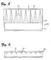
- FIGS. 5 and 6 show further sealing means 50 which are attached to the right vertical edge of the baffle 3, to effect the sealing of the butt joints between the baffles of adjacent locking elements in devices with a plurality or plurality of locking elements.
- the joint seal 50 extends from the upper edge of the wall 3 to below the sealing region 9 on the buoyancy body 4.
- the wall 3 projects laterally over the float, so that this supernatant engages behind the vertical sealing means of a blocking element on the left and the two Walls are sealed against each other.
- the vertical sealing means 50 extend down to a region between adjacent buoyancy bodies.
- the sealing means 50 thereby ensure that the sealing of the butt joints extends below the horizontal sealing area on the rear side of the blocking elements, thereby keeping the flood protection device tight in the area between adjacent blocking bodies.
- the vertical sealing means do not restrict the relative vertical mobility of the locking body to each other and are designed so that they do not catch or hinder each other when floating.
- the geometry of the shaft elements is designed such that narrow guides with small tolerances between locking body, in particular the buoyancy body and the shaft walls are avoided.
- FIG. 1 and the FIG. 2 such a system is shown in which the rear wall 52 of the shaft 5 is exempted up to an upper region 51 soiling such as stones or branches, which can penetrate into the shaft, especially when used in rivers, place in the spaces 56 space and obstruct the Mobility of the locking body 2 in the shaft 5 not.
- FIG. 1 In the FIG. 1 is indicated that can be accommodated in the shaft 5 or in a separate compartment 57 below the shaft 5 as additional benefits other installations such as cable ducts or other lines.
- the shaft is preferably made on site, for example, with a wall thickness of 14 cm made of reinforced concrete, cast steel fiber or polymer fiber concrete, or prefabricated finished parts of such materials are installed in corresponding trenches In both cases, civil engineering work is required, with little overhead as described above can be used.
- the devices are not sunk in the ground, but formed as parts of infrastructure in the bank area
- the device according to the present invention may serve as part of quay walls or as above-ground barrier walls, which in an emergency by means of extendable barrier body to increase the effective height of the dam wall.
Landscapes
- Engineering & Computer Science (AREA)
- General Engineering & Computer Science (AREA)
- Environmental & Geological Engineering (AREA)
- Ocean & Marine Engineering (AREA)
- Mechanical Engineering (AREA)
- Civil Engineering (AREA)
- Structural Engineering (AREA)
- Barrages (AREA)
- Revetment (AREA)
Applications Claiming Priority (1)
| Application Number | Priority Date | Filing Date | Title |
|---|---|---|---|
| CH1072007 | 2007-01-24 |
Publications (2)
| Publication Number | Publication Date |
|---|---|
| EP1950352A2 true EP1950352A2 (fr) | 2008-07-30 |
| EP1950352A3 EP1950352A3 (fr) | 2013-07-03 |
Family
ID=39367699
Family Applications (1)
| Application Number | Title | Priority Date | Filing Date |
|---|---|---|---|
| EP08000903.8A Withdrawn EP1950352A3 (fr) | 2007-01-24 | 2008-01-18 | Dispositif de protection contre les inondations |
Country Status (1)
| Country | Link |
|---|---|
| EP (1) | EP1950352A3 (fr) |
Cited By (6)
| Publication number | Priority date | Publication date | Assignee | Title |
|---|---|---|---|---|
| NL1035546C2 (en) * | 2008-05-13 | 2009-11-16 | Den Noort Innovations B V Van | Self-closing flood barrier and method for protecting a hinterland using the same. |
| ITPC20100015A1 (it) * | 2010-06-11 | 2011-12-12 | Sverzellati Antonio Riccardo | Barriere mobile idrauliche |
| WO2012084783A1 (fr) | 2010-12-20 | 2012-06-28 | Floodprotect Limited | Corps de barrage pour un dispositif de barrage et procédé de fabrication |
| WO2013189895A1 (fr) | 2012-06-18 | 2013-12-27 | Floodprotect Limited | Dispositif de barrage et procédé de fabrication d'un dispositif de barrage |
| GB2524874A (en) * | 2014-02-13 | 2015-10-07 | Bluewater Design Associates Ltd | Self-activating flood protection barrier |
| CN107313498A (zh) * | 2017-08-17 | 2017-11-03 | 北京北排装备产业有限公司 | 一种智能化井口防汛筒及其使用方法 |
Citations (2)
| Publication number | Priority date | Publication date | Assignee | Title |
|---|---|---|---|---|
| EP0726364A1 (fr) | 1995-02-09 | 1996-08-14 | Van den Noort, Johann Heinrich Reindert | Digne mobile |
| WO2000001892A1 (fr) | 1998-07-03 | 2000-01-13 | Fiona Meikle | Dispositif pour la prevention des inondations |
Family Cites Families (1)
| Publication number | Priority date | Publication date | Assignee | Title |
|---|---|---|---|---|
| DE10201882A1 (de) * | 2002-01-18 | 2003-07-31 | Roland Wegener | Hochwasserschutzeinrichtung |
-
2008
- 2008-01-18 EP EP08000903.8A patent/EP1950352A3/fr not_active Withdrawn
Patent Citations (2)
| Publication number | Priority date | Publication date | Assignee | Title |
|---|---|---|---|---|
| EP0726364A1 (fr) | 1995-02-09 | 1996-08-14 | Van den Noort, Johann Heinrich Reindert | Digne mobile |
| WO2000001892A1 (fr) | 1998-07-03 | 2000-01-13 | Fiona Meikle | Dispositif pour la prevention des inondations |
Cited By (10)
| Publication number | Priority date | Publication date | Assignee | Title |
|---|---|---|---|---|
| NL1035546C2 (en) * | 2008-05-13 | 2009-11-16 | Den Noort Innovations B V Van | Self-closing flood barrier and method for protecting a hinterland using the same. |
| ITPC20100015A1 (it) * | 2010-06-11 | 2011-12-12 | Sverzellati Antonio Riccardo | Barriere mobile idrauliche |
| WO2012084783A1 (fr) | 2010-12-20 | 2012-06-28 | Floodprotect Limited | Corps de barrage pour un dispositif de barrage et procédé de fabrication |
| WO2013189895A1 (fr) | 2012-06-18 | 2013-12-27 | Floodprotect Limited | Dispositif de barrage et procédé de fabrication d'un dispositif de barrage |
| GB2524874A (en) * | 2014-02-13 | 2015-10-07 | Bluewater Design Associates Ltd | Self-activating flood protection barrier |
| CN105980633A (zh) * | 2014-02-13 | 2016-09-28 | 蓝水设计联合有限公司 | 自激活式防洪屏障 |
| GB2524874B (en) * | 2014-02-13 | 2017-03-08 | Bluewater Design Ass Ltd | Self-activating flood protection barrier |
| US9689129B2 (en) | 2014-02-13 | 2017-06-27 | Bluewater Design Associates Limited | Self-activating flood protection barrier |
| CN105980633B (zh) * | 2014-02-13 | 2018-12-07 | 卓纳吉设计有限公司 | 自激活式防洪屏障 |
| CN107313498A (zh) * | 2017-08-17 | 2017-11-03 | 北京北排装备产业有限公司 | 一种智能化井口防汛筒及其使用方法 |
Also Published As
| Publication number | Publication date |
|---|---|
| EP1950352A3 (fr) | 2013-07-03 |
Similar Documents
| Publication | Publication Date | Title |
|---|---|---|
| DE69628299T2 (de) | Uferhochwasserschutzwand | |
| DE102008009519B3 (de) | Wasserabsperrung, insbesondere Hochwasserschutzwand | |
| EP1950352A2 (fr) | Dispositif de protection contre les inondations | |
| DE202018102880U1 (de) | Schott für den Hochwasserschutz und Durchgang mit einem solchen Schott | |
| DE4010221C2 (fr) | ||
| DE102017130818B3 (de) | Wassersperre mit einem rinnenförmigen Gründungkörper | |
| EP1586707A2 (fr) | Mur contre les crues | |
| DE102004033962B4 (de) | Versenkbare Flutwasserschutzanlage | |
| DE10201882A1 (de) | Hochwasserschutzeinrichtung | |
| DE10348024A1 (de) | Rigolenanordnung mit Rigole und Schacht | |
| EP1731682B1 (fr) | Système de canalisation à cascade pour eaux de surface | |
| AT508757B1 (de) | Hydraulische hochwasserschutzwand | |
| DE19646271C2 (de) | Hochwasserschutzwand | |
| DE102014008895A1 (de) | Hydrodynamisches Wehr zur Verhinderung der Sohlerosion in Flüssen und zur Erhaltung der Schiffbarkeit bei Niedrigwasser | |
| DE102004015322B4 (de) | Hochwasserbarriere | |
| DE10023750C1 (de) | Vorrichtung zum Verhindern des Wasseraustritts aus Kanalöffnungen bei Hochwasser | |
| DE10326802A1 (de) | Einrichtung zum Hochwasserschutz | |
| DE20308083U1 (de) | Hochwasser-Schutzsystem | |
| DE4301137C1 (de) | Stauklappenwehr | |
| DE202009005371U1 (de) | Wasserfülldamm für den Schutz vor Überschwemmungen | |
| DE10239036A1 (de) | Vorrichtung zum Schutz vor Überschwemmungen und Überflutungen | |
| DE880119C (de) | Abschlußvorrichtung für Schleusen, Häfen, Docks oder Wasserläufe | |
| DE1634168C (de) | Vorrichtung zum Ausgleich zwischen dem Wasserstand von Schiffahrtskanalen u dgl und einem hoher hegenden Grundwasser spiegel mittels Rückschlagventilen | |
| DE3502243A1 (de) | Vorrichtung zum verschliessen von gewaessern | |
| DE2157652A1 (de) | Einsetzbarer bodenablauf in ein eingemauertes gehaeuse |
Legal Events
| Date | Code | Title | Description |
|---|---|---|---|
| PUAI | Public reference made under article 153(3) epc to a published international application that has entered the european phase |
Free format text: ORIGINAL CODE: 0009012 |
|
| AK | Designated contracting states |
Kind code of ref document: A2 Designated state(s): AT BE BG CH CY CZ DE DK EE ES FI FR GB GR HR HU IE IS IT LI LT LU LV MC MT NL NO PL PT RO SE SI SK TR |
|
| AX | Request for extension of the european patent |
Extension state: AL BA MK RS |
|
| PUAL | Search report despatched |
Free format text: ORIGINAL CODE: 0009013 |
|
| AK | Designated contracting states |
Kind code of ref document: A3 Designated state(s): AT BE BG CH CY CZ DE DK EE ES FI FR GB GR HR HU IE IS IT LI LT LU LV MC MT NL NO PL PT RO SE SI SK TR |
|
| AX | Request for extension of the european patent |
Extension state: AL BA MK RS |
|
| RIC1 | Information provided on ipc code assigned before grant |
Ipc: E02B 3/10 20060101AFI20130527BHEP |
|
| 17P | Request for examination filed |
Effective date: 20131224 |
|
| RBV | Designated contracting states (corrected) |
Designated state(s): AT BE BG CH CY CZ DE DK EE ES FI FR GB GR HR HU IE IS IT LI LT LU LV MC MT NL NO PL PT RO SE SI SK TR |
|
| AKX | Designation fees paid |
Designated state(s): AT BE BG CH CY CZ DE DK EE ES FI FR GB GR HR HU IE IS IT LI LT LU LV MC MT NL NO PL PT RO SE SI SK TR |
|
| RAP1 | Party data changed (applicant data changed or rights of an application transferred) |
Owner name: NIEDERDORFER, NIRMALA |
|
| STAA | Information on the status of an ep patent application or granted ep patent |
Free format text: STATUS: THE APPLICATION IS DEEMED TO BE WITHDRAWN |
|
| 18D | Application deemed to be withdrawn |
Effective date: 20150801 |