EP1950384A1 - Kühlmittel enthaltendes hohles tellerventil und herstellungsverfahren dafür - Google Patents
Kühlmittel enthaltendes hohles tellerventil und herstellungsverfahren dafür Download PDFInfo
- Publication number
- EP1950384A1 EP1950384A1 EP05806844A EP05806844A EP1950384A1 EP 1950384 A1 EP1950384 A1 EP 1950384A1 EP 05806844 A EP05806844 A EP 05806844A EP 05806844 A EP05806844 A EP 05806844A EP 1950384 A1 EP1950384 A1 EP 1950384A1
- Authority
- EP
- European Patent Office
- Prior art keywords
- valve
- poppet valve
- cup
- hollow poppet
- shaped object
- Prior art date
- Legal status (The legal status is an assumption and is not a legal conclusion. Google has not performed a legal analysis and makes no representation as to the accuracy of the status listed.)
- Granted
Links
Images





Classifications
-
- F—MECHANICAL ENGINEERING; LIGHTING; HEATING; WEAPONS; BLASTING
- F01—MACHINES OR ENGINES IN GENERAL; ENGINE PLANTS IN GENERAL; STEAM ENGINES
- F01L—CYCLICALLY OPERATING VALVES FOR MACHINES OR ENGINES
- F01L3/00—Lift-valve, i.e. cut-off apparatus with closure members having at least a component of their opening and closing motion perpendicular to the closing faces; Parts or accessories thereof
- F01L3/12—Cooling of valves
- F01L3/14—Cooling of valves by means of a liquid or solid coolant, e.g. sodium, in a closed chamber in a valve
-
- F—MECHANICAL ENGINEERING; LIGHTING; HEATING; WEAPONS; BLASTING
- F01—MACHINES OR ENGINES IN GENERAL; ENGINE PLANTS IN GENERAL; STEAM ENGINES
- F01L—CYCLICALLY OPERATING VALVES FOR MACHINES OR ENGINES
- F01L3/00—Lift-valve, i.e. cut-off apparatus with closure members having at least a component of their opening and closing motion perpendicular to the closing faces; Parts or accessories thereof
- F01L3/02—Selecting particular materials for valve-members or valve-seats; Valve-members or valve-seats composed of two or more materials
-
- F—MECHANICAL ENGINEERING; LIGHTING; HEATING; WEAPONS; BLASTING
- F16—ENGINEERING ELEMENTS AND UNITS; GENERAL MEASURES FOR PRODUCING AND MAINTAINING EFFECTIVE FUNCTIONING OF MACHINES OR INSTALLATIONS; THERMAL INSULATION IN GENERAL
- F16K—VALVES; TAPS; COCKS; ACTUATING-FLOATS; DEVICES FOR VENTING OR AERATING
- F16K1/00—Lift valves or globe valves, i.e. cut-off apparatus with closure members having at least a component of their opening and closing motion perpendicular to the closing faces
- F16K1/32—Details
- F16K1/34—Cutting-off parts, e.g. valve members, seats
- F16K1/36—Valve members
-
- F—MECHANICAL ENGINEERING; LIGHTING; HEATING; WEAPONS; BLASTING
- F16—ENGINEERING ELEMENTS AND UNITS; GENERAL MEASURES FOR PRODUCING AND MAINTAINING EFFECTIVE FUNCTIONING OF MACHINES OR INSTALLATIONS; THERMAL INSULATION IN GENERAL
- F16K—VALVES; TAPS; COCKS; ACTUATING-FLOATS; DEVICES FOR VENTING OR AERATING
- F16K25/00—Details relating to contact between valve members and seats
-
- F—MECHANICAL ENGINEERING; LIGHTING; HEATING; WEAPONS; BLASTING
- F16—ENGINEERING ELEMENTS AND UNITS; GENERAL MEASURES FOR PRODUCING AND MAINTAINING EFFECTIVE FUNCTIONING OF MACHINES OR INSTALLATIONS; THERMAL INSULATION IN GENERAL
- F16K—VALVES; TAPS; COCKS; ACTUATING-FLOATS; DEVICES FOR VENTING OR AERATING
- F16K49/00—Means in or on valves for heating or cooling
- F16K49/005—Circulation means for a separate heat transfer fluid
- F16K49/007—Circulation means for a separate heat transfer fluid located within the obturating element
-
- F—MECHANICAL ENGINEERING; LIGHTING; HEATING; WEAPONS; BLASTING
- F01—MACHINES OR ENGINES IN GENERAL; ENGINE PLANTS IN GENERAL; STEAM ENGINES
- F01L—CYCLICALLY OPERATING VALVES FOR MACHINES OR ENGINES
- F01L2301/00—Using particular materials
-
- F—MECHANICAL ENGINEERING; LIGHTING; HEATING; WEAPONS; BLASTING
- F01—MACHINES OR ENGINES IN GENERAL; ENGINE PLANTS IN GENERAL; STEAM ENGINES
- F01L—CYCLICALLY OPERATING VALVES FOR MACHINES OR ENGINES
- F01L2303/00—Manufacturing of components used in valve arrangements
-
- F—MECHANICAL ENGINEERING; LIGHTING; HEATING; WEAPONS; BLASTING
- F01—MACHINES OR ENGINES IN GENERAL; ENGINE PLANTS IN GENERAL; STEAM ENGINES
- F01L—CYCLICALLY OPERATING VALVES FOR MACHINES OR ENGINES
- F01L2820/00—Details on specific features characterising valve gear arrangements
- F01L2820/01—Absolute values
-
- Y—GENERAL TAGGING OF NEW TECHNOLOGICAL DEVELOPMENTS; GENERAL TAGGING OF CROSS-SECTIONAL TECHNOLOGIES SPANNING OVER SEVERAL SECTIONS OF THE IPC; TECHNICAL SUBJECTS COVERED BY FORMER USPC CROSS-REFERENCE ART COLLECTIONS [XRACs] AND DIGESTS
- Y10—TECHNICAL SUBJECTS COVERED BY FORMER USPC
- Y10T—TECHNICAL SUBJECTS COVERED BY FORMER US CLASSIFICATION
- Y10T29/00—Metal working
- Y10T29/49—Method of mechanical manufacture
- Y10T29/49229—Prime mover or fluid pump making
- Y10T29/49298—Poppet or I.C. engine valve or valve seat making
- Y10T29/49307—Composite or hollow valve stem or head making
Definitions
- This invention relates to a hollow poppet valve charged with a coolant and having sufficient heat resistance, wear resistance, and strength in accord with required use conditions of the valve, and to a method of manufacturing such hollow poppet valve. More particularly, the invention relates to a hollow poppet valve having a cap that is integrally welded to the fillet portion that is integrally formed at one end of the cylindrical stem portion of the poppet valve, and to a method of manufacturing such hollow poppet valve.
- FIG. 8 A typical prior art poppet is disclosed in the patent document cited below. As shown in Fig. 8 , this prior art hollow poppet valve has a thick edge (hereinafter referred to as thick portion) at the upper open end of the fillet region provided at the upper end of a cylindrical stem portion (G region) of the hollow poppet valve.
- a cap welding portion A is provided on the inside of the thick part and away from the seat portion 150 (of E region). It is anticipated that the seat portion 150 retains a higher Vickers hardness in the range from 300 to 349HV than regions A, B, C, and D, whose Vickers hardnesses are lowered by welding heat. Thus, the seat portion 150 is anticipated to have sufficient wear resistance against repeated abutment with a cylinder to maintain the seat portion 150 in intimate contact with the cylinder during closing/opening operation of the valve.
- CITED PATENT DOCUMENT 1 International Publication W0 00/No. 47876.
- Fig. 9 shows measured fatigue strengths (ordinate) of cold-worked austenitic-stainless-steel materials for hollow poppet valves after they were hardened to three different levels of hardness (151, 316, and 380 HV in Vickers hardness) and subjected to 10 million times of fatigue tests under different temperatures (abscissa).
- Fig. 10 shows creep strengths (ordinate) of the same materials as shown in Fig. 9 , which were also cold-worked to three different levels of hardness and tested at 600 °C. The abscissa represents value of Larson Mirror parameter.
- fatigue strength of the material having hardness of 380 HV quickly decreases when used at or above 400 °C, and, when used at 600 °C, decreases to a level comparable to that of the material having hardness of 151 HV, which level is far below the fatigue strength of the material having hardness of 316 HV.
- valve material hardened to 380 HV is used at 600 °C, it looses creep strength greatly in time as compared with the materials hardened to 151 and 316 HV.
- a reason for this great loss in fatigue and creep strengths of the material which was initially hardened to 380 HV and used at 600 C° may be due to recrystallization of the texture of the material caused by hardening to 380 HV.
- the cold-worked head portion, i. e. the fillet region 14 of the valve is subjected to repetitive strong tensile stresses and fails to retain required fat igue strength and creep strength, thereby resulting in problematic ruptures for example.
- the stem portion of the poppet valve or the cylindrical shaft portion that corresponds to region G extending downward from the lower end of the head portion as shown in Fig. 8 is in sliding contact with the valve guide section of the cylinder and repeatedly subjected to tensile stresses in the same manner as the head portion.
- it is cold worked to the same hardness as the head portion, it suffers the same problem that it cannot retain necessary fatigue strength and wear resistance.
- the seat portion 15 that comes into contact with the seat metal of a cylinder needs to be cold worked harder than the head portion in order to allow the seat portion to come into intimate contact with the cylinder as much as possible, otherwise it cannot sustain wear resistance necessary to secure the intimate contact.
- this invention seeks to provide a cold-worked, heat-treated hollow poppet valve charged with a coolant, and a method of manufacturing such poppet valve, such that the valve has a fillet region (or head portion) having sufficient fatigue strength and creep strength to stand repetitive use at high temperatures.
- the invention further seeks to provide a hollow poppet valve charged with a coolant and having a stem portion (or shaft portion) having predetermined fatigue strength and wear resistance and a seat portion having predetermined wear resistance.
- the invention also seeks to provide a method of manufacturing such hollow poppet valve.
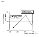
- the head portion Since the hardness of the head portion is maintained between about 250 HV and 350 HV inclusive, the head portion does not undergo a recrystallization that would otherwise take place when the head portion is hardened to 380HV for example and used at a high temperature. Accordingly, significant decline of fatigue strength and creep strength of the head portion as indicated by 380 HV curve in Fig. 9 and 10 will not take place if the valve is used repeatedly at high temperatures, and will maintain necessary fatigue strength and creep strength, as shown in Fig. 5 .
- the stem portion of the hollow poppet valve charged with a coolant as defined in claim 1 may be hardened to Vickers hardness of about 350 HV or more, as defined in claim 2.
- the surface layer of the tapered seat portion of the hollow poppet valve charged with a coolant as defined in claim 1 or 2 may be hardened to Vickers hardness of about 380 HV or more as defined in claim 3.
- the surface layer of the seat portion By hardening the surface layer of the seat portion to about 380 HV or more, the surface layer can secure a wear resistance necessary to maintain intimate contact thereof with the seat metal of the cylinder.
- the shaft portion of the hollow poppet valve as defined in claim 4 may be hardened to Vickers hardness of 350 HV or more in the steps of cold drawing, as defined in claim 5.
- the shaft portion of the hollow poppet valve as defined in claim 2 can be fabricated to retain necessary fatigue strength against repeated abutment against a cylinder, and wear resistance against sliding contact with the valve guide of the cylinder.
- the surface layer of the seat portion of the hollow poppet valve may be hardened to Vickers hardness of about 380 HV or more in the steps of cold forming subsequent to the cold drawing, as defined in claim 6.
- the hollow poppet valve charged with a coolant in accord with claim 1 of the invention can retain sufficient fatigue strength and creep strength if the head portion is used repeatedly at high temperatures. Since there is no fear that the hollow poppet valve is fractured if used under such conditions, the valve is suited for use in an internal combustion engine that is internally heated to a high temperature.
- the hollow poppet valve in accord with claim 2 has an enhanced strength against the repetitive stresses acted on the shaft portion by a cylinder and enhanced strength against the friction with the valve guide of the cylinder, the shaft portion can retain required fatigue strength and wear resistance.
- the poppet valve in accord with claim 3 has a seat portion that has sufficient anti-wear strength that it can retain intimate contact with the seat metal of the cylinder during its repetitive abutment with the cylinder
- a method in accord with claim 4 enables manufacture of a hollow poppet valve charged with a coolant suitable for use in an internal combustion engine that is internally heated to a high temperature.
- This method also enables manufacture of a hollow poppet valve having a strong shaft portion that can resist against repetitive tensile stresses and frictions.
- the method in accord with claim 5 enables manufacture of a hollow poppet valve having a strong shaft that can withstand repetitive contact forces applied thereto by a cylinder and frictional forces applied thereto by the valve guide of the cylinder.
- the method in accord with claim 6 further enables manufacture of a valve having a seat portion that can maintain intimate contact with the seat metal of the cylinder during its repetitive abutment with the cylinder.
- Fig. 1 shows a front view, partly cut away, of a hollow poppet valve 10
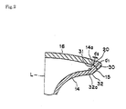
- Fig. 2 shows an enlarged cross section of the cap welding portion of the valve.
- the poppet valve 10 has a hollow cylindrical shaft portion 12 having a closed lower end, and a head portion 14 integrally formed on top of the shaft portion 12 and having a flared upper open end.
- the shaft portion 12 is formed to have a substantially uniform thickness, but the head portion 14 is formed of a wall that gradually increases in thickness towards the upper open end thereof ( Fig. 1 ).
- the open end has a thick edge 30 having a seat portion on the periphery thereof such that heat applied to the cap welding portion to weld a cap will not influence on the seat portion 15.
- a disk-shaped cap 10 is integrally welded to the open edge of the head portion 14.
- Reference numeral 18 indicates a cotter groove formed on the outer periphery of the lower end of the shaft portion 12.
- Reference numeral 19 refers to a tip portion formed at the lower end of the shaft portion 12.
- An austenitic stainless steel of SUS304 or SUS305, for example, may be used as a valve material.
- the coolant can be a liquid metal such as potassium sodium for example.
- the tip portion 19 is cut away from the valve to charge a coolant. After the poppet valve is charged with the coolant, another tip piece 19 is welded to close the valve.
- the coolant not only facilitates conduction of heat from the head portion 14 to the tip portion 19, but also helps reduce the weight of the valve.
- a piece of blank material W1 is cold worked or cold pressed into a cup-shaped object W2, as shown in Fig. 3 (a-b).
- this cold pressing process includes a step of forming a flanged thick edge 30a on the open end of the cup-shaped object W2.
- intermediate annealing is applied.
- the intermediate annealing is performed at least once subsequent to the cold pressing and prior to the cold drawing. If the material is still too hard to press, additional annealing may be applied between the cold pressing and the cold drawing as described below.
- the cup-shaped object W2 is worked by cold drawing using transfer presses, as shown in Fig. 3 (c-d).
- the cylindrical shaft portion 12, head portion 14 having a flared opening at the open end of the cup-shaped article, and tapered seat portion 15 on the outer periphery of the open end are formed.
- a predetermined hollow poppet valve having a flared open head portion 14 is obtained.
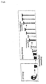
- the process of cold drawing includes a multiplicity of steps in which the cold pressed cup-shaped object (shown at the far left of Fig. 4 ) is forced into a little narrower drawing die, and then the resultant narrowed object is further forced into a still narrower drawing die, and so on, until a desirably drew object results, as shown in Fig. 4 . Since various parts of the valve are hardened every time the object is pressed into a drawing die and drawn, the object is annealed as needed during the drawing in order not to harden the resultant valve too hard. Fig.
- FIG. 5 shows the fatigue strength (ordinate) of a material (which is SUS305 in the example shown herein) versus Vickers hardness (abscissa) at 600 °C, which is a temperature the valve is possibly heated to in use.
- the value of 300 MPa marked on the ordinate represents the fatigue strength required of the head portion 14.
- the fatigue strength of this material increases with hardness even after it exceeds required fatigue strength of 300 MPa at the hardness of about 240 HV, up until the hardness reaches about 316 HV.
- the fatigue strength then begins to decrease with hardness, and becomes less than the required fatigue strength of 300 MPa when the hardness exceeds about 360 HV. Therefore, taking account of variations of the valves manufactured, it is recommended to harden valves in the range between 250 HV and 350 HV inclusive in order to maintain the fatigue strength of the head portion of a valve not less than 300 MPa.
- Fig. 6 also shows Vickers hardness (abscissa) versus fatigue strength (ordinate) of the same material (SUS305) as in Fig. 5 in the temperature range from 25 to 400 °C.
- This temperature range reflects the use conditions of the shaft portion 12 of the valve. Since fatigue strength decreases with temperature, it is an important issue whether deterioration in fatigue strength of the shaft portion takes place at 400 °C. Incidentally, the strength of 500 MPa is the fatigue strength required of the shaft portion 12.
- the hardness of the seat portion 15 is preferably hardened to about 380 HV or more in view of the wear resistance of the surface layer of the seat portion 15.
- valve material is worked into a predetermined form, it is annealed in an intermediate annealing step to suppress the hardness of the material below 350 HV, thereby suppressing the hardness of the resultant head portion 14 below the maximum allowable hardness of about 350 HV.
- the shaft portion 12 is repeatedly drawn so that the hardness thereof will be not be less than 350 HV after it is worked into a predetermined form.
- the seat portion 15 is repeatedly cold forged to increase its hardness until the hardness exceeds 380 HV.
- the head portion 14, shaft portion 12, and the seat portion 15 are preferably hardened to the respective minimum allowable hardness.
- a mandrel may be used as needed.
- the cotter groove 18 is fabricated in the lower end section of the shaft portion 12 by, for example, a roll forming process.
- a cap 10 which has been manufactured independently of the shaft portion 12 is electronbeam welded or laserbeam welded onto the recessed step 14a formed inside the head portion 14.
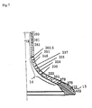
- Fig. 7 shows measured Vickers hardness at various points in the shaft portion 12, head portion 14, and seat portion 15 of a trial valve.
- the lower right portion of the valve (first region) extending from the point of 370 HV to the point of 402 HV as shown corresponds to the seat portion 15; a second region above the first region and extending from the point of 279 HV to the point of 351 HV corresponds to the head portion 14; and a third region above the second region and extending from the point of 360.5 HV to the point of 390 HV corresponds to the shaft portion 12.
Landscapes
- Engineering & Computer Science (AREA)
- General Engineering & Computer Science (AREA)
- Mechanical Engineering (AREA)
- Physics & Mathematics (AREA)
- Thermal Sciences (AREA)
- Forging (AREA)
- Heat Treatment Of Articles (AREA)
- Lift Valve (AREA)
Applications Claiming Priority (1)
| Application Number | Priority Date | Filing Date | Title |
|---|---|---|---|
| PCT/JP2005/020975 WO2007057946A1 (ja) | 2005-11-15 | 2005-11-15 | 冷媒入り中空ポペットバルブおよびその製造方法 |
Publications (3)
| Publication Number | Publication Date |
|---|---|
| EP1950384A1 true EP1950384A1 (de) | 2008-07-30 |
| EP1950384A4 EP1950384A4 (de) | 2009-11-25 |
| EP1950384B1 EP1950384B1 (de) | 2014-03-19 |
Family
ID=38048338
Family Applications (1)
| Application Number | Title | Priority Date | Filing Date |
|---|---|---|---|
| EP05806844.6A Expired - Lifetime EP1950384B1 (de) | 2005-11-15 | 2005-11-15 | Kühlmittel enthaltendes hohles tellerventil und herstellungsverfahren dafür |
Country Status (6)
| Country | Link |
|---|---|
| US (1) | US20090266314A1 (de) |
| EP (1) | EP1950384B1 (de) |
| JP (1) | JP4871293B2 (de) |
| KR (1) | KR100981100B1 (de) |
| CN (1) | CN101305168B (de) |
| WO (1) | WO2007057946A1 (de) |
Cited By (2)
| Publication number | Priority date | Publication date | Assignee | Title |
|---|---|---|---|---|
| EP2541002A4 (de) * | 2010-02-26 | 2013-10-16 | Mitsubishi Heavy Ind Ltd | Verfahren zur herstellung eines motorhohlventils |
| EP2933445A1 (de) * | 2014-04-08 | 2015-10-21 | Man Diesel & Turbo, Filial Af Man Diesel & Turbo Se, Tyskland | Auslassventil für einen verbrennungsmotor und verfahren zur verstärkung eines ringventilsitzbereichs eines auslassventils |
Families Citing this family (14)
| Publication number | Priority date | Publication date | Assignee | Title |
|---|---|---|---|---|
| JP4968734B2 (ja) * | 2007-08-02 | 2012-07-04 | バブコック日立株式会社 | オーステナイト鋼の使用温度推定方法 |
| JP4390291B1 (ja) * | 2008-09-18 | 2009-12-24 | 株式会社 吉村カンパニー | 中空エンジンバルブの弁傘部の製造方法及び中空エンジンバルブ |
| JP5297402B2 (ja) * | 2010-02-26 | 2013-09-25 | 三菱重工業株式会社 | 金属ナトリウム封入エンジンバルブの製造方法 |
| JP5574752B2 (ja) * | 2010-02-26 | 2014-08-20 | 三菱重工業株式会社 | 中空エンジンバルブの製造方法 |
| JP5485011B2 (ja) * | 2010-05-12 | 2014-05-07 | 三菱重工業株式会社 | 金属ナトリウム封入エンジンバルブの製造方法 |
| DE102012008945A1 (de) * | 2012-05-05 | 2013-11-07 | Mahle International Gmbh | Kolben für einen Verbrennungsmotor |
| CN104053868B (zh) * | 2012-10-02 | 2016-08-17 | 日锻汽门株式会社 | 空心提升阀 |
| WO2014167694A1 (ja) * | 2013-04-11 | 2014-10-16 | 日鍛バルブ株式会社 | 中空ポペットバルブ |
| DE102017114509A1 (de) * | 2017-06-29 | 2019-01-03 | Federal-Mogul Valvetrain Gmbh | Hohlraumventil mit optimierter Schaftinnengeometrie und Verfahren zu dessen Herstellung |
| KR102285017B1 (ko) | 2018-03-20 | 2021-08-04 | 니탄 밸브 가부시키가이샤 | 배기용 중공 포핏 밸브 |
| CN112752895B (zh) | 2018-11-12 | 2023-10-13 | 日锻株式会社 | 发动机的提升阀的制造方法 |
| US10787939B1 (en) | 2019-04-01 | 2020-09-29 | Cyclazoom, LLC | Poppet valve for internal combustion engine |
| JP7329201B2 (ja) | 2020-03-30 | 2023-08-18 | 株式会社Nittan | エンジンのポペットバルブの製造方法 |
| US11506091B2 (en) * | 2021-03-03 | 2022-11-22 | Cyclazoom, LLC | Poppet valve and internal combustion piston engine head including same |
Family Cites Families (22)
| Publication number | Priority date | Publication date | Assignee | Title |
|---|---|---|---|---|
| US2734008A (en) * | 1956-02-07 | Method of making heat treating and hardening valves | ||
| US2183254A (en) * | 1937-06-28 | 1939-12-12 | Eaton Mfg Co | Valve structure and method of forming |
| US2119042A (en) * | 1937-12-20 | 1938-05-31 | Eaton Mfg Co | Valve |
| US2452628A (en) * | 1944-08-25 | 1948-11-02 | Thompson Prod Inc | Method of making hollow poppet valves |
| US2731708A (en) * | 1952-10-31 | 1956-01-24 | Teves Kg Alfred | Process for manufacture of hollow poppet valves especially for internal-combustion engines |
| US2948052A (en) * | 1956-06-30 | 1960-08-09 | Teves Kg Alfred | Method of manufacturing hollow poppet valves for internal combustion engines |
| US2949907A (en) * | 1957-12-19 | 1960-08-23 | Thompson Ramo Wooldridge Inc | Coolant-filled poppet valve and method of making same |
| US4741080A (en) * | 1987-02-20 | 1988-05-03 | Eaton Corporation | Process for providing valve members having varied microstructure |
| JPS63264237A (ja) * | 1987-04-22 | 1988-11-01 | Aisan Ind Co Ltd | 中空バルブ素材の製造方法 |
| JPS6483676A (en) * | 1987-09-28 | 1989-03-29 | Toyota Motor Corp | Wear resistant al alloy member |
| NL8702446A (nl) | 1987-10-14 | 1989-05-01 | Barend Willem Hak | Werkwijze ter bereiding van een veterinair- en humaanmedisch preparaat met antivirale en antitumorale werking, alsmede het in farmaceutisch toepasbare vorm gebrachte preparaat. |
| US5413073A (en) * | 1993-04-01 | 1995-05-09 | Eaton Corporation | Ultra light engine valve |
| US5458314A (en) * | 1993-04-01 | 1995-10-17 | Eaton Corporation | Temperature control in an ultra light engine valve |
| JPH08176752A (ja) * | 1994-12-26 | 1996-07-09 | Aichi Steel Works Ltd | 冷鍛性に優れたマルテンサイト系耐熱鋼 |
| CN1091212C (zh) * | 1997-01-29 | 2002-09-18 | 富士乌兹克斯株式会社 | 内燃机中的空心气门 |
| JPH1132525A (ja) * | 1997-07-17 | 1999-02-09 | Iseki & Co Ltd | 農作業機の旋回操作装置 |
| JPH1162525A (ja) * | 1997-08-07 | 1999-03-05 | Fuji Oozx Inc | 内燃機関用バルブ及びその製造方法 |
| EP0911493A3 (de) | 1997-10-21 | 2000-04-12 | Eaton Corporation | Verbesserte Spitzengestaltung in einem ultraleichten Brennkraftmaschinenventil |
| US6378543B1 (en) * | 1999-02-12 | 2002-04-30 | Nittan Valve Co., Ltd. | Hollow poppet valve and the method for manufacturing the same |
| US6263849B1 (en) * | 1999-07-20 | 2001-07-24 | Eaton Corporation | Ultra light engine valve and method of welding cap thereto |
| JP2001323323A (ja) * | 2000-05-12 | 2001-11-22 | Aichi Steel Works Ltd | 自動車用エンジンバルブの製造方法 |
| US6679478B2 (en) * | 2000-07-17 | 2004-01-20 | Nittan Valve Co., Ltd. | Hollow poppet valve and method for manufacturing the same |
-
2005
- 2005-11-15 CN CN2005800520594A patent/CN101305168B/zh not_active Expired - Fee Related
- 2005-11-15 US US12/093,364 patent/US20090266314A1/en not_active Abandoned
- 2005-11-15 EP EP05806844.6A patent/EP1950384B1/de not_active Expired - Lifetime
- 2005-11-15 JP JP2007545120A patent/JP4871293B2/ja not_active Expired - Fee Related
- 2005-11-15 WO PCT/JP2005/020975 patent/WO2007057946A1/ja not_active Ceased
- 2005-11-15 KR KR1020087011668A patent/KR100981100B1/ko not_active Expired - Fee Related
Cited By (3)
| Publication number | Priority date | Publication date | Assignee | Title |
|---|---|---|---|---|
| EP2541002A4 (de) * | 2010-02-26 | 2013-10-16 | Mitsubishi Heavy Ind Ltd | Verfahren zur herstellung eines motorhohlventils |
| US8881391B2 (en) | 2010-02-26 | 2014-11-11 | Mitsubishi Heavy Industries, Ltd. | Method for producing hollow engine valve |
| EP2933445A1 (de) * | 2014-04-08 | 2015-10-21 | Man Diesel & Turbo, Filial Af Man Diesel & Turbo Se, Tyskland | Auslassventil für einen verbrennungsmotor und verfahren zur verstärkung eines ringventilsitzbereichs eines auslassventils |
Also Published As
| Publication number | Publication date |
|---|---|
| CN101305168B (zh) | 2010-05-12 |
| US20090266314A1 (en) | 2009-10-29 |
| EP1950384B1 (de) | 2014-03-19 |
| KR100981100B1 (ko) | 2010-09-08 |
| EP1950384A4 (de) | 2009-11-25 |
| CN101305168A (zh) | 2008-11-12 |
| JPWO2007057946A1 (ja) | 2009-04-30 |
| JP4871293B2 (ja) | 2012-02-08 |
| KR20080070004A (ko) | 2008-07-29 |
| WO2007057946A1 (ja) | 2007-05-24 |
Similar Documents
| Publication | Publication Date | Title |
|---|---|---|
| EP1950384A1 (de) | Kühlmittel enthaltendes hohles tellerventil und herstellungsverfahren dafür | |
| EP2740908B1 (de) | Verfahren zur herstellung von tellerventilsitzflächen und tellerventile mit nach diesem verfahren hergestellten sitzflächen | |
| RU2644089C2 (ru) | Термомеханическая обработка высокопрочного немагнитного коррозионно-стойкого материала | |
| US9610630B2 (en) | Closed-die forging method and method of manufacturing forged article | |
| EP0526174B1 (de) | Verfahren zur Herstellung eines Auslassventiles | |
| KR20080106917A (ko) | 고강도 스테인리스강 스프링 및 그 제조 방법 | |
| EP3390679B1 (de) | Hochlegierte edelstahlschmiedeteile ohne lösungsglühen | |
| US6354001B1 (en) | Method of manufacturing a Ti alloy poppet value | |
| CN108453471A (zh) | 铆接螺母和制造这样的螺母的方法 | |
| EP2327804B1 (de) | Abgas tellerventil und lösungsglühbehandlung des tellerventils | |
| Kitamura et al. | Cold joining of rotor shaft with flange by using plastic deformation | |
| Kwon et al. | Failure analysis of the exhaust valve stem from a Waukesha P9390 GSI gas engine | |
| EP3815809B1 (de) | Blindnietmutter und herstellungsverfahren dafür | |
| KR20010039718A (ko) | 대형 구성요소 부품의 단조 방법 | |
| JP4116983B2 (ja) | チタン製バルブスプリングリテーナ | |
| Yu et al. | Failure analysis of diesel engine rocker arms | |
| Slater et al. | A novel forming technique to coforge bimetal components into complex geometries | |
| CN115697584A (zh) | 发动机的提升阀的制造方法 | |
| Bannykh et al. | Effect of hot-rolling and heat-treatment conditions on the structure and mechanical and technological properties of nitrogen-bearing austenitic steel 05Kh22AG15N8M2F-Sh | |
| Lam | Tensile Properties of High-Strength Connecting Rod Bolts | |
| RU2003108427A (ru) | Шатун двигателя внутреннего сгорания, способ его изготовления (варианты) | |
| Elban et al. | Metallurgical characterization of refrigeration tubing formed from plain carbon steel strip stock |
Legal Events
| Date | Code | Title | Description |
|---|---|---|---|
| PUAI | Public reference made under article 153(3) epc to a published international application that has entered the european phase |
Free format text: ORIGINAL CODE: 0009012 |
|
| 17P | Request for examination filed |
Effective date: 20080515 |
|
| AK | Designated contracting states |
Kind code of ref document: A1 Designated state(s): DE FR GB IT SE |
|
| DAX | Request for extension of the european patent (deleted) | ||
| RBV | Designated contracting states (corrected) |
Designated state(s): DE FR GB IT SE |
|
| A4 | Supplementary search report drawn up and despatched |
Effective date: 20091028 |
|
| 17Q | First examination report despatched |
Effective date: 20100216 |
|
| GRAP | Despatch of communication of intention to grant a patent |
Free format text: ORIGINAL CODE: EPIDOSNIGR1 |
|
| RIC1 | Information provided on ipc code assigned before grant |
Ipc: F16K 1/36 20060101ALI20130917BHEP Ipc: F16K 25/00 20060101ALI20130917BHEP Ipc: F01L 3/02 20060101AFI20130917BHEP Ipc: F01L 3/14 20060101ALN20130917BHEP |
|
| INTG | Intention to grant announced |
Effective date: 20131004 |
|
| GRAS | Grant fee paid |
Free format text: ORIGINAL CODE: EPIDOSNIGR3 |
|
| GRAA | (expected) grant |
Free format text: ORIGINAL CODE: 0009210 |
|
| AK | Designated contracting states |
Kind code of ref document: B1 Designated state(s): DE FR GB IT SE |
|
| REG | Reference to a national code |
Ref country code: GB Ref legal event code: FG4D |
|
| REG | Reference to a national code |
Ref country code: DE Ref legal event code: R096 Ref document number: 602005043033 Country of ref document: DE Effective date: 20140430 |
|
| REG | Reference to a national code |
Ref country code: SE Ref legal event code: TRGR |
|
| REG | Reference to a national code |
Ref country code: DE Ref legal event code: R097 Ref document number: 602005043033 Country of ref document: DE |
|
| PLBE | No opposition filed within time limit |
Free format text: ORIGINAL CODE: 0009261 |
|
| STAA | Information on the status of an ep patent application or granted ep patent |
Free format text: STATUS: NO OPPOSITION FILED WITHIN TIME LIMIT |
|
| 26N | No opposition filed |
Effective date: 20141222 |
|
| REG | Reference to a national code |
Ref country code: DE Ref legal event code: R097 Ref document number: 602005043033 Country of ref document: DE Effective date: 20141222 |
|
| REG | Reference to a national code |
Ref country code: FR Ref legal event code: PLFP Year of fee payment: 11 |
|
| REG | Reference to a national code |
Ref country code: FR Ref legal event code: PLFP Year of fee payment: 12 |
|
| REG | Reference to a national code |
Ref country code: FR Ref legal event code: PLFP Year of fee payment: 13 |
|
| PGFP | Annual fee paid to national office [announced via postgrant information from national office to epo] |
Ref country code: SE Payment date: 20201125 Year of fee payment: 16 Ref country code: DE Payment date: 20201119 Year of fee payment: 16 Ref country code: GB Payment date: 20201120 Year of fee payment: 16 Ref country code: FR Payment date: 20201120 Year of fee payment: 16 Ref country code: IT Payment date: 20201124 Year of fee payment: 16 |
|
| REG | Reference to a national code |
Ref country code: DE Ref legal event code: R119 Ref document number: 602005043033 Country of ref document: DE |
|
| GBPC | Gb: european patent ceased through non-payment of renewal fee |
Effective date: 20211115 |
|
| PG25 | Lapsed in a contracting state [announced via postgrant information from national office to epo] |
Ref country code: SE Free format text: LAPSE BECAUSE OF NON-PAYMENT OF DUE FEES Effective date: 20211116 |
|
| PG25 | Lapsed in a contracting state [announced via postgrant information from national office to epo] |
Ref country code: GB Free format text: LAPSE BECAUSE OF NON-PAYMENT OF DUE FEES Effective date: 20211115 Ref country code: DE Free format text: LAPSE BECAUSE OF NON-PAYMENT OF DUE FEES Effective date: 20220601 |
|
| PG25 | Lapsed in a contracting state [announced via postgrant information from national office to epo] |
Ref country code: FR Free format text: LAPSE BECAUSE OF NON-PAYMENT OF DUE FEES Effective date: 20211130 |
|
| PG25 | Lapsed in a contracting state [announced via postgrant information from national office to epo] |
Ref country code: IT Free format text: LAPSE BECAUSE OF NON-PAYMENT OF DUE FEES Effective date: 20211115 |