EP1950406A2 - Système de recyclage de gaz d'échappement - Google Patents
Système de recyclage de gaz d'échappement Download PDFInfo
- Publication number
- EP1950406A2 EP1950406A2 EP07024125A EP07024125A EP1950406A2 EP 1950406 A2 EP1950406 A2 EP 1950406A2 EP 07024125 A EP07024125 A EP 07024125A EP 07024125 A EP07024125 A EP 07024125A EP 1950406 A2 EP1950406 A2 EP 1950406A2
- Authority
- EP
- European Patent Office
- Prior art keywords
- exhaust gas
- egr
- catalyst
- flow rate
- gas flow
- Prior art date
- Legal status (The legal status is an assumption and is not a legal conclusion. Google has not performed a legal analysis and makes no representation as to the accuracy of the status listed.)
- Withdrawn
Links
- 239000003054 catalyst Substances 0.000 claims abstract description 137
- 238000001514 detection method Methods 0.000 claims abstract description 41
- 239000000126 substance Substances 0.000 claims abstract description 39
- 238000011144 upstream manufacturing Methods 0.000 claims abstract description 9
- 238000003745 diagnosis Methods 0.000 claims description 4
- 230000008859 change Effects 0.000 claims description 3
- 230000003134 recirculating effect Effects 0.000 claims description 2
- 230000007423 decrease Effects 0.000 abstract description 5
- 239000007789 gas Substances 0.000 description 42
- 238000000746 purification Methods 0.000 description 22
- 238000000034 method Methods 0.000 description 18
- 238000001179 sorption measurement Methods 0.000 description 16
- 230000006866 deterioration Effects 0.000 description 13
- 238000010586 diagram Methods 0.000 description 10
- MWUXSHHQAYIFBG-UHFFFAOYSA-N Nitric oxide Chemical compound O=[N] MWUXSHHQAYIFBG-UHFFFAOYSA-N 0.000 description 9
- 238000002485 combustion reaction Methods 0.000 description 9
- 238000005259 measurement Methods 0.000 description 9
- 239000013618 particulate matter Substances 0.000 description 8
- 239000000446 fuel Substances 0.000 description 7
- 230000003647 oxidation Effects 0.000 description 7
- 238000007254 oxidation reaction Methods 0.000 description 7
- 230000008569 process Effects 0.000 description 5
- OKTJSMMVPCPJKN-UHFFFAOYSA-N Carbon Chemical compound [C] OKTJSMMVPCPJKN-UHFFFAOYSA-N 0.000 description 4
- 229910052799 carbon Inorganic materials 0.000 description 4
- 239000000498 cooling water Substances 0.000 description 3
- 230000003247 decreasing effect Effects 0.000 description 3
- 230000002542 deteriorative effect Effects 0.000 description 3
- 238000006722 reduction reaction Methods 0.000 description 3
- QVGXLLKOCUKJST-UHFFFAOYSA-N atomic oxygen Chemical compound [O] QVGXLLKOCUKJST-UHFFFAOYSA-N 0.000 description 2
- 230000000694 effects Effects 0.000 description 2
- 238000002347 injection Methods 0.000 description 2
- 239000007924 injection Substances 0.000 description 2
- 239000001301 oxygen Substances 0.000 description 2
- 229910052760 oxygen Inorganic materials 0.000 description 2
- 230000004043 responsiveness Effects 0.000 description 2
- 239000004071 soot Substances 0.000 description 2
- 230000004913 activation Effects 0.000 description 1
- 230000008901 benefit Effects 0.000 description 1
- 230000005674 electromagnetic induction Effects 0.000 description 1
- 238000010438 heat treatment Methods 0.000 description 1
- WABPQHHGFIMREM-UHFFFAOYSA-N lead(0) Chemical compound [Pb] WABPQHHGFIMREM-UHFFFAOYSA-N 0.000 description 1
- 238000000691 measurement method Methods 0.000 description 1
- 239000003507 refrigerant Substances 0.000 description 1
- 239000002689 soil Substances 0.000 description 1
- 238000009834 vaporization Methods 0.000 description 1
- 230000008016 vaporization Effects 0.000 description 1
Images






Classifications
-
- F—MECHANICAL ENGINEERING; LIGHTING; HEATING; WEAPONS; BLASTING
- F02—COMBUSTION ENGINES; HOT-GAS OR COMBUSTION-PRODUCT ENGINE PLANTS
- F02D—CONTROLLING COMBUSTION ENGINES
- F02D41/00—Electrical control of supply of combustible mixture or its constituents
- F02D41/0025—Controlling engines characterised by use of non-liquid fuels, pluralities of fuels, or non-fuel substances added to the combustible mixtures
- F02D41/0047—Controlling exhaust gas recirculation [EGR]
- F02D41/005—Controlling exhaust gas recirculation [EGR] according to engine operating conditions
-
- F—MECHANICAL ENGINEERING; LIGHTING; HEATING; WEAPONS; BLASTING
- F02—COMBUSTION ENGINES; HOT-GAS OR COMBUSTION-PRODUCT ENGINE PLANTS
- F02M—SUPPLYING COMBUSTION ENGINES IN GENERAL WITH COMBUSTIBLE MIXTURES OR CONSTITUENTS THEREOF
- F02M26/00—Engine-pertinent apparatus for adding exhaust gases to combustion-air, main fuel or fuel-air mixture, e.g. by exhaust gas recirculation [EGR] systems
- F02M26/13—Arrangement or layout of EGR passages, e.g. in relation to specific engine parts or for incorporation of accessories
- F02M26/35—Arrangement or layout of EGR passages, e.g. in relation to specific engine parts or for incorporation of accessories with means for cleaning or treating the recirculated gases, e.g. catalysts, condensate traps, particle filters or heaters
-
- F—MECHANICAL ENGINEERING; LIGHTING; HEATING; WEAPONS; BLASTING
- F02—COMBUSTION ENGINES; HOT-GAS OR COMBUSTION-PRODUCT ENGINE PLANTS
- F02M—SUPPLYING COMBUSTION ENGINES IN GENERAL WITH COMBUSTIBLE MIXTURES OR CONSTITUENTS THEREOF
- F02M26/00—Engine-pertinent apparatus for adding exhaust gases to combustion-air, main fuel or fuel-air mixture, e.g. by exhaust gas recirculation [EGR] systems
- F02M26/45—Sensors specially adapted for EGR systems
- F02M26/46—Sensors specially adapted for EGR systems for determining the characteristics of gases, e.g. composition
- F02M26/47—Sensors specially adapted for EGR systems for determining the characteristics of gases, e.g. composition the characteristics being temperatures, pressures or flow rates
-
- F—MECHANICAL ENGINEERING; LIGHTING; HEATING; WEAPONS; BLASTING
- F02—COMBUSTION ENGINES; HOT-GAS OR COMBUSTION-PRODUCT ENGINE PLANTS
- F02M—SUPPLYING COMBUSTION ENGINES IN GENERAL WITH COMBUSTIBLE MIXTURES OR CONSTITUENTS THEREOF
- F02M26/00—Engine-pertinent apparatus for adding exhaust gases to combustion-air, main fuel or fuel-air mixture, e.g. by exhaust gas recirculation [EGR] systems
- F02M26/49—Detecting, diagnosing or indicating an abnormal function of the EGR system
-
- F—MECHANICAL ENGINEERING; LIGHTING; HEATING; WEAPONS; BLASTING
- F02—COMBUSTION ENGINES; HOT-GAS OR COMBUSTION-PRODUCT ENGINE PLANTS
- F02B—INTERNAL-COMBUSTION PISTON ENGINES; COMBUSTION ENGINES IN GENERAL
- F02B2275/00—Other engines, components or details, not provided for in other groups of this subclass
- F02B2275/14—Direct injection into combustion chamber
-
- F—MECHANICAL ENGINEERING; LIGHTING; HEATING; WEAPONS; BLASTING
- F02—COMBUSTION ENGINES; HOT-GAS OR COMBUSTION-PRODUCT ENGINE PLANTS
- F02B—INTERNAL-COMBUSTION PISTON ENGINES; COMBUSTION ENGINES IN GENERAL
- F02B29/00—Engines characterised by provision for charging or scavenging not provided for in groups F02B25/00, F02B27/00 or F02B33/00 - F02B39/00; Details thereof
- F02B29/04—Cooling of air intake supply
- F02B29/0406—Layout of the intake air cooling or coolant circuit
-
- F—MECHANICAL ENGINEERING; LIGHTING; HEATING; WEAPONS; BLASTING
- F02—COMBUSTION ENGINES; HOT-GAS OR COMBUSTION-PRODUCT ENGINE PLANTS
- F02D—CONTROLLING COMBUSTION ENGINES
- F02D41/00—Electrical control of supply of combustible mixture or its constituents
- F02D41/0025—Controlling engines characterised by use of non-liquid fuels, pluralities of fuels, or non-fuel substances added to the combustible mixtures
- F02D41/0047—Controlling exhaust gas recirculation [EGR]
- F02D41/0065—Specific aspects of external EGR control
- F02D41/0072—Estimating, calculating or determining the EGR rate, amount or flow
- F02D2041/0075—Estimating, calculating or determining the EGR rate, amount or flow by using flow sensors
-
- F—MECHANICAL ENGINEERING; LIGHTING; HEATING; WEAPONS; BLASTING
- F02—COMBUSTION ENGINES; HOT-GAS OR COMBUSTION-PRODUCT ENGINE PLANTS
- F02M—SUPPLYING COMBUSTION ENGINES IN GENERAL WITH COMBUSTIBLE MIXTURES OR CONSTITUENTS THEREOF
- F02M26/00—Engine-pertinent apparatus for adding exhaust gases to combustion-air, main fuel or fuel-air mixture, e.g. by exhaust gas recirculation [EGR] systems
- F02M26/02—EGR systems specially adapted for supercharged engines
- F02M26/04—EGR systems specially adapted for supercharged engines with a single turbocharger
- F02M26/05—High pressure loops, i.e. wherein recirculated exhaust gas is taken out from the exhaust system upstream of the turbine and reintroduced into the intake system downstream of the compressor
-
- F—MECHANICAL ENGINEERING; LIGHTING; HEATING; WEAPONS; BLASTING
- F02—COMBUSTION ENGINES; HOT-GAS OR COMBUSTION-PRODUCT ENGINE PLANTS
- F02M—SUPPLYING COMBUSTION ENGINES IN GENERAL WITH COMBUSTIBLE MIXTURES OR CONSTITUENTS THEREOF
- F02M26/00—Engine-pertinent apparatus for adding exhaust gases to combustion-air, main fuel or fuel-air mixture, e.g. by exhaust gas recirculation [EGR] systems
- F02M26/02—EGR systems specially adapted for supercharged engines
- F02M26/04—EGR systems specially adapted for supercharged engines with a single turbocharger
- F02M26/06—Low pressure loops, i.e. wherein recirculated exhaust gas is taken out from the exhaust downstream of the turbocharger turbine and reintroduced into the intake system upstream of the compressor
-
- F—MECHANICAL ENGINEERING; LIGHTING; HEATING; WEAPONS; BLASTING
- F02—COMBUSTION ENGINES; HOT-GAS OR COMBUSTION-PRODUCT ENGINE PLANTS
- F02M—SUPPLYING COMBUSTION ENGINES IN GENERAL WITH COMBUSTIBLE MIXTURES OR CONSTITUENTS THEREOF
- F02M26/00—Engine-pertinent apparatus for adding exhaust gases to combustion-air, main fuel or fuel-air mixture, e.g. by exhaust gas recirculation [EGR] systems
- F02M26/13—Arrangement or layout of EGR passages, e.g. in relation to specific engine parts or for incorporation of accessories
- F02M26/22—Arrangement or layout of EGR passages, e.g. in relation to specific engine parts or for incorporation of accessories with coolers in the recirculation passage
- F02M26/23—Layout, e.g. schematics
- F02M26/28—Layout, e.g. schematics with liquid-cooled heat exchangers
-
- Y—GENERAL TAGGING OF NEW TECHNOLOGICAL DEVELOPMENTS; GENERAL TAGGING OF CROSS-SECTIONAL TECHNOLOGIES SPANNING OVER SEVERAL SECTIONS OF THE IPC; TECHNICAL SUBJECTS COVERED BY FORMER USPC CROSS-REFERENCE ART COLLECTIONS [XRACs] AND DIGESTS
- Y02—TECHNOLOGIES OR APPLICATIONS FOR MITIGATION OR ADAPTATION AGAINST CLIMATE CHANGE
- Y02T—CLIMATE CHANGE MITIGATION TECHNOLOGIES RELATED TO TRANSPORTATION
- Y02T10/00—Road transport of goods or passengers
- Y02T10/10—Internal combustion engine [ICE] based vehicles
- Y02T10/40—Engine management systems
Definitions
- the present invention relates to an exhaust gas recirculation (EGR) system for an internal combustion engine and more particularly to a technique for furnishing an EGR path with an EGR sensor for detecting the amount of EGR.
- EGR exhaust gas recirculation
- EGR rate exhaust gas recirculation rate
- the detection accuracy of the EGR sensor decreases.
- carbon or other substances are deposited in the EGR path in the case where the EGR sensor calculates a flow rate from the flow velocity of EGR gas, the inside diameter of the pipe decreases, leading to the problem that the EGR flow rate cannot be accurately calculated from the flow velocity.
- An object of the present invention is to provide a technique for preventing the EGR flow rate detection accuracy of an EGR sensor installed in an EGR path of an engine from being decreased due to a soiling substances entry into the EGR path.
- Another object of the present invention is to ensure that EGR control can be steadily exercised in accordance with a sensor signal even when the EGR flow rate detection accuracy of the EGR sensor is decreased.
- Still another object of the present invention is to prevent an EGR system from operating in accordance with a wrong signal of the EGR sensor.
- the present invention includes a catalyst for purifying the EGR gas or exhaust.
- the catalyst is positioned upstream of the EGR sensor, which detects the amount of EGR in the EGR path. While the catalyst is active, the present invention can prevent the EGR sensor from being soiled because the catalyst purifies soiling substances contained in the EGR gas or exhaust.
- the EGR sensor have a flow rate measurement mode and a soilure protection mode.
- control is exercised to place the EGR sensor in the soilure protection mode in which the sensor protects itself against flowing soiling substances (e.g., in an output stop state or in a heating state in which a heater burns soiling substances away).
- the catalyst is active, on the other hand, control is exercised to place the EGR sensor in the flow rate measurement mode. Consequently, the EGR sensor is less likely to be affected by soiling substances in the exhaust under any circumstances of the EGR path. Since this prevents the accuracy of EGR gas detection from decreasing, it is possible to prevent the deterioration of engine combustion state and exhaust.
- the present invention which has been described above, includes a catalyst that is installed upstream of the EGR sensor to purify soiling substances in the EGR gas. This allows the EGR sensor to substantially avert the influence of soiling substances in the exhaust and to avoid a decrease in the accuracy of EGR gas flow rate detection. As a result, it is possible to avoid the deterioration of engine combustion state and exhaust.
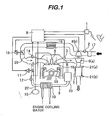
- Fig. 1 shows the configuration of an engine according to a first embodiment of the present invention.
- the reference numeral 19 denotes the engine.
- an air cleaner 17 Positioned upstream of the engine 19 are an air cleaner 17; an air flow sensor 2; a compressor 6(b) for a supercharger; an intercooler 16; a throttle valve 13 for intake air amount adjustment; an intake path 20; and a fuel injection valve (hereinafter referred to as the injector) 5.
- Intake air amount control means is composed of the compressor 6(b), intercooler 16, and throttle valve 13, whereas intake air amount detection means is the air flow sensor 2.
- the injector 5 is designed to directly inject fuel into a combustion chamber 18. It is preferred that the throttle valve 13 be electronically controlled.
- the throttle valve 13 of the present embodiment is driven by an electric actuator.
- the intake path 20 is provided with an intake pressure sensor 14, which detects the pressure within the intake path 20. The detected intake pressure is used to correct the output of the air flow sensor 2 for the purpose of increasing the accuracy of intake air amount control.
- the exhaust pipe is provided with a ⁇ sensor (O 2 sensor) 3 for measuring the air-fuel ratio of an exhaust gas emitted from the engine, an EGR path 9 for recirculating the exhaust to the intake path 20, an EGR cooler 10 which uses engine cooling water as a refrigerant and cools recirculated exhaust gas by exchanging heat between the recirculated exhaust gas and engine cooling water, and an EGR flow control valve 11.
- the present invention is characterized by the configuration in which the EGR path 9 is provided with an EGR flow sensor 12, which detects an EGR flow rate, and an EGR catalyst 23.
- the responsiveness of the EGR flow sensor 12 requires a detection period within at least one cycle of each operating condition set. Therefore, it is preferred that a hot-wire flow sensor or an electromagnetic flow sensor be used as the EGR flow sensor 12.
- the hot-wire flow sensor exposes a resistive element to an exhaust gas flow, sends a current to the resistive element, and measures the flow rate of exhaust gas by detecting a current change that represents the amount of heat absorbed by the exhaust gas.
- the electromagnetic flow sensor is a measuring instrument based on Faraday's law of electromagnetic induction.
- It measures electromotive force that is generated in exhaust gas when the exhaust gas flows in a magnetic field. More specifically, it uses an electrode, which is placed in a pipe that serves as an exhaust gas flow path, to measure a current that arises due to the generated electromotive force in accordance with Fleming's right-hand rule and flows to the exhaust gas, which serves as a conductive gas, and determines the exhaust gas flow rate from the relationship between average exhaust gas flow velocity and electromotive force.
- the principles of the hot-wire flow sensor will be described in detail later with reference to Fig. 2 .
- the EGR catalyst 23 is installed to prevent the EGR path 9 from being soiled. It is preferred that the EGR catalyst 23 be a purification catalyst based on oxidation or reduction reaction such as a three-way catalyst or an oxidation catalyst. It is also preferred that the EGR catalyst 23 be positioned upstream of the EGR cooler 10 as shown in Fig. 1 .
- the injector 5 injects a predetermined amount of fuel in accordance with target engine torque that is calculated, for instance, from a depression amount signal ⁇ of an accelerator opening sensor 1.
- a fuel injection amount is corrected on an as-needed basis in accordance, for instance, with an opening signal ⁇ tp of the throttle valve 13, an opening signal ⁇ EGR of the EGR flow control valve 11, a boost pressure Ptin of the compressor 6(b), and an output value of the ⁇ sensor 3.
- An oxygen sensor (O 2 sensor), CO 2 sensor, or other sensor capable of estimating in-cylinder oxygen concentration may be used as the ⁇ sensor 3.
- the reference numeral 8 denotes an engine control unit (hereinafter referred to as the ECU).
- the ECU 8 determines, for instance, the combustion mode and control variables of the engine 19 in accordance with a user request such as an accelerator depression amount (also referred to as the accelerator opening) ⁇ or brake status, vehicle conditions such as vehicle velocity, and engine operating conditions such as an engine cooling water temperature and exhaust temperature.
- the present invention places the output processing status of the EGR flow sensor 12 in a soilure protection mode or nullifies the signal of the EGR flow sensor 12 depending on the activation status of the EGR catalyst 23, and calculates and outputs an opening control signal of the EGR flow control valve 11 in accordance with an output signal of the EGR flow sensor 12.
- the soilure protection mode includes a mode in which a high current flows to a sensor element of the EGR flow sensor 12 and burns soiling substances attached to the sensor element, as will hereinafter be described.
- the above configuration prevents the EGR path 9, intake path 20, EGR flow control valve 11, and throttle valve 13 from being soiled by PM (particulate matter) or other substances emitted from the engine 19, and enhances the durability of the engine.
- This sensor uses two different thermal resistive elements.
- One of them is a resistance temperature detector, which detects the temperature of a gas that is to be measured.
- the other is set at a relatively high temperature (operating temperature: approximately 200 to 300°C) and controlled such that the temperature difference between the two thermal resistive elements remains unchanged at all times.
- the employed configuration includes a hot wire 27 and a lead wire 28 as shown in Fig. 2A .
- a control circuit controls the temperatures of both of them, and the current control state of that particular time is used to detect the amount of intake gas.
- This thermal configuration excels in output responsiveness to a change in the gas flow rate. Therefore, most of current automotive intake flow meters employ this thermal flow meter.
- the EGR flow sensor 12 employs the soilure protection mode to provide control so that the temperature of the hot wire 27 can be temporarily raised to burn the PM. This makes it possible not only to burn PM and other soiling substances but also to prevent soiling substances being newly attached to the hot wire 27. In this instance, it is preferred that the temperature of the hot wire 27 be raised to 600°C or higher. However, such a temperature varies depending on the engine employed.
- Fig. 3 is a typical diagram illustrating a situation where the soilure protection mode of the EGR sensor is used in accordance with the first embodiment of the present invention.
- the engine according to the present invention exercises control as shown in Fig. 3 to prevent the EGR flow sensor 12 from being soiled and deteriorated.
- Line L1 in the diagram represents the surface temperature of the hot wire 27.
- Line L2 represents a status flag of the EGR flow sensor 12 to be judged in the ECU 8.
- Line L3 represents the temperature of the EGR catalyst 23.
- the temperature of the EGR catalyst 23 rises as indicated by line L3 to start light-off.
- purification is not sufficiently performed by the EGR catalyst 23. Therefore, the EGR flow sensor 12 still remains in the soilure protection mode.
- exhaust purification becomes achievable. Accordingly, the EGR flow sensor 12 enters a measurement mode as indicated by line L2 so that the surface temperature of the hot wire 27 can be changed as appropriate for measurement.
- the ECU exercises control such that the hot wire 27 enters a high-current conduction state and functions as a heater while the EGR catalyst 23 is inactive and enters a small-current conduction state and functions as a sensor while the EGR catalyst 23 is active.
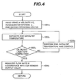
- Fig. 4 is a temperature control flowchart concerning the EGR catalyst 23, explaining Fig. 3 in more detail.
- block 1001s is performed.
- the vehicle velocity Vc, accelerator opening ⁇ , engine operating status, and other conditions of a vehicle in which the engine 19 is mounted are read.
- block 1002s is performed to estimate the current temperature of the EGR catalyst 23.
- the procedure then proceeds to block 1003s. If the judgment result obtained in block 1003s indicates that catalyst light-off is completed, block 1004s is performed to exit the protection mode of the EGR flow sensor 12, start to detect the gas flow rate, and use the detection results for engine control.
- Fig. 5 is a flowchart illustrating a method of judging whether the EGR catalyst 23 is deteriorated. Since the deterioration of the EGR catalyst 23 leads to soilure of the EGR path 9 and other devices, it is necessary to accurately judge whether the EGR catalyst 23 is deteriorated.
- the control of the EGR catalyst 23 in Fig. 5 is the same as that in Fig. 4 . However, as shown in Fig. 5 , if the judgment result obtained in block 1003s indicates that the light-off of the EGR catalyst 23 is completed, the ECU 8 detects the time required from the engine startup to the completion of the light-off of the EGR catalyst 23. Block 1006s is then performed to judge whether the detected time is longer than a predetermined value. If the detected time is not longer than the predetermined value, block 1004s is performed to exit the protection mode of the EGR flow sensor 12, start to detect the gas flow rate, and use the detection results for engine control.
- the detected time is longer than the predetermined value, it is highly probable that it took a longer time for the EGR catalyst 23 to complete the light-off, that is, the EGR catalyst 23 has deteriorated.
- This judgment result is stored in the ECU 8, reported, for instance, to the user as a warning, or otherwise processed as prescribed by the vehicle or engine. If at least the function to prevent soilure of the EGR flow sensor 12 remains unaffected, the engine operation can be continued. Such a deterioration judgment as formulated above allows the EGR flow sensor 12 to avoid soiling substances with the conditions of EGR catalyst 23 being considered.
- the second embodiment uses a DPF (diesel particulate filter) or other similar adsorption or occlusion catalyst as the EGR catalyst.
- DPF diesel particulate filter
- other similar adsorption or occlusion catalyst as the EGR catalyst.
- Fig. 6 shows the configuration of an engine according to the second embodiment of the present invention.
- the second embodiment uses a DPF or other similar adsorption or occlusion catalyst as the EGR catalyst 24, as described above.
- This EGR catalyst 24 does not have a so-called "light-off" characteristic but can adsorb (occlude) a predetermined amount of soiling substances even at a low temperature.
- the catalyst configuration according to the second embodiment is at an advantage in that it can provide higher purification efficiency than the catalyst configuration according to the first embodiment. Therefore, it is possible to prevent the EGR flow sensor 12 and EGR path 9 from becoming soiled even in an engine which has many conditions for relatively-low-temperature operations.
- a control method for the EGR flow sensor 12 according to the second embodiment will now be described.
- Fig. 7 is a typical diagram illustrating a situation where the protection mode of the EGR sensor is used in accordance with the second embodiment.
- Line L4 in the diagram represents the surface temperature of the hot wire 27.
- Line L5 represents a status flag of the EGR flow sensor 12 to be judged in the ECU 8.
- Line L6 represents the temperature of the EGR catalyst 24.
- the EGR catalyst 24 is operative and adsorbs (occludes) soiling substances and the like even right after the engine starts up.
- the temperature is low, the soiling substances in the engine exhaust cannot be properly purified as in the case of the first embodiment because the purification efficiency (adsorption efficiency) is low.
- the EGR flow sensor 12 enters the soilure protection mode to raise the temperature of the hot wire 27 preferably to 600°C or higher as indicated by lines L4 and L5. This makes it possible to burn soiling substances attached to the surface of the hot wire 27 and to avoid the attachment of soiling substances during the soilure protection mode. It is preferred that the EGR flow sensor 12 refrain from performing a flow rate detection operation during this interval. Subsequently, after the engine operates for a certain period of time, the temperature of the EGR catalyst 24 rises as indicated by line L6 and reaches catalyst temperature T1 at time t1. At temperature T1, the purification efficiency of the EGR catalyst 24 exceeds a predetermined value. Therefore, the EGR flow sensor 12 enters the measurement mode as indicated by line L5, and the surface temperature of the hot wire 27 is changed as appropriate for measurement.
- Fig. 8 is a temperature control flowchart concerning the EGR catalyst 24, explaining Fig. 7 in more detail.
- the basic flow is the same as that of the first embodiment ( Fig. 4 ).
- a different criterion is used in block 1013s. If the judgment result obtained in block 1013s indicates that a value obtained in block 1012s exceeds a predetermined value, it means that the purification efficiency of the EGR catalyst 24 exceeds the predetermined value. Accordingly, the EGR flow sensor 12 exits the protection mode, starts to detect the gas flow rate (block 1014s), and uses the detection results for engine control. If, on the other hand, the value obtained in block 1012s does not exceed the predetermined value, the judgment process is repeatedly performed until the predetermined value is reached.
- the use of the above flow makes it possible to properly prevent the EGR flow sensor 12 from becoming soiled and deteriorating and to accurately detect an EGR gas flow rate no matter whether an adsorption (occlusion) catalyst is employed as the EGR catalyst 24.
- Fig. 9 is a flowchart illustrating a method of judging whether the EGR catalyst 24 is deteriorated. If the adsorption (occlusion) EGR catalyst 24 is deteriorated, the EGR path 9, devices, and other parts may become soiled. In addition, a pressure drop may occur in the EGR path 9. Since these phenomena may make it impossible to exercise an accurate EGR flow rate control, it is necessary to accurately judge whether the EGR catalyst 24 is deteriorated.
- the EGR flow sensor 12 exits the protection mode, starts to detect the gas flow rate (block 1014s), and uses the detection results for engine control, as indicated in Fig 9 .
- an output value generated from the air flow sensor 2 is simultaneously used to calculate the EGR flow rate (block 1015s).
- Block 1016s is then performed to judge whether the obtained difference between the output value from the air flow sensor 2 and the calculated EGR flow rate is within a predetermined range. While the engine is performing a steady operation, even a calculated EGR flow rate value based on the air flow sensor output value has an error rate of not greater than 3% or so.
- the calculation result obtained in block 1016s is infinitely close to zero.
- the output values of the EGR sensor are more subject to the effects of soilure or deterioration than those of the air flow sensor 2 due to the environment of the EGR path 9.
- the calculation result obtained in block 1016s is not within the predetermined range, it means that the EGR flow sensor 12 is considerably soiled and that the EGR catalyst 24 is not properly functioning.
- the deterioration of the EGR catalyst 24 can be diagnosed in accordance with the calculation result (block 1017s) to perform a necessary process. It is needless to say that the present embodiment can exercise control to place the EGR flow sensor 12 again in the protection mode in accordance with the calculation result and to avoid soilure.
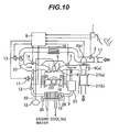
- Fig. 10 shows the configuration of an engine according to a third embodiment of the present invention.
- the third embodiment is configured such that a bypass flow path 25 is positioned in the EGR flow path 9 before and after the EGR cooler 10, and a control valve 26 is positioned in the EGR flow path 9 before the EGR cooler 10.
- a bypass flow path 25 is positioned in the EGR flow path 9 before and after the EGR cooler 10
- a control valve 26 is positioned in the EGR flow path 9 before the EGR cooler 10.
- Such a configuration is employed so that a predetermined amount of the EGR gas of a relatively high temperature, which does not pass through the EGR cooler 10, can be returned to the intake path at a cold startup. This raises the gas temperature at the combustion chamber 18 to facilitate fuel vaporization and to reduce the exhaust of PM and the like.
- the EGR flow sensor 12 can accurately detect the EGR flow rate in accordance with engine operating conditions and control variables provided by the control valve 26.
- a three-way catalyst, an oxidation catalyst, or other purification catalysts based on oxidation or reduction reaction be used as the EGR catalyst 23.
- the use of a DPF or other similar adsorption or occlusion catalysts causes no particular problem.
- Fig. 11 shows the configuration of an engine according to a fourth embodiment of the present invention.
- the fourth embodiment differs from the foregoing embodiments in the engine configuration. More specifically, the EGR path 9 is positioned as a path that connects the rear of an exhaust catalyst 7 to the compressor 6(b) for the supercharger. Further, the throttle valve 13, which adjusts the intake air amount, is positioned immediately downstream of the air cleaner 17 and upstream of a connecting hole on the intake side of the EGR path 9. Since this configuration enables the exhaust catalyst 7 to function as an EGR catalyst, the EGR catalyst is unnecessary. Consequently, the costs of the system can be reduced.
- the exhaust catalyst 7 is a combination of a three-way catalyst, an oxidation catalyst, or other purification catalysts based on oxidation or reduction reaction and a DPF, NOx catalyst, or other adsorption or occlusion catalysts.
- a purification catalyst e.g., oxidation catalyst
- an adsorption catalyst e.g., DPF
- the air flow sensor 2 and EGR flow sensor 12 are virtually equidistant from the engine combustion chamber 18, the air flow sensor 2 may also be excluded from the system. However, this matter will not be described in detail because it is not intended to be included in the scope of the present invention.
- Fig. 12 is a typical diagram illustrating a situation where the protection mode of the EGR sensor is used in accordance with the fourth embodiment.
- Line L7 in the diagram represents the surface temperature of the hot wire 27.
- Line L8 represents a status flag of the EGR flow sensor 12, which is to be judged by the ECU 8.
- Line L9 represents the temperature of the EGR catalyst 23.
- the adsorption catalyst in the combined catalyst is more or less capable of exercising its adsorption function even when the temperature is low, as shown in Fig. 7 . Therefore, the purification characteristic of the exhaust catalyst 7 that prevails at a low temperature is governed by the characteristic of the purification catalyst in the combined catalyst. Consequently, it is possible to properly prevent the EGR flow sensor 12 from becoming soiled and deteriorating when control is exercised as described above.
- a certain condition of the exhaust catalyst 7 may incur the soilure and deterioration of EGR flow sensor 12 and affect EGR flow rate detection. It is therefore necessary to judge whether the exhaust catalyst 7 is deteriorated, as in the case of the first and second embodiments.
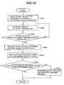
- Figs. 13 and 14 are flowcharts illustrating how to judge whether the exhaust catalyst 7 is deteriorated. These figures are deterioration diagnosis flowcharts for the purification catalyst and adsorption catalyst, respectively. These flowcharts are combined to diagnose the exhaust catalyst 7.
- Fig. 13 shows steps that are followed to judge whether the purification catalyst in the combined catalyst is deteriorated.
- the steps indicated in this figure are basically the same as the diagnosis steps for the EGR catalyst 23, which are shown in Fig. 5 .
- block 1021s is performed to read the vehicle velocity Vc, accelerator opening ⁇ , engine operating status, and other conditions of a vehicle in which the engine 19 is mounted.
- Block 1022s is then performed to estimate the current temperature of the exhaust catalyst 7.
- the procedure proceeds to block 1023s to judge whether light-off is completed. If light-off is not completed, it means that the temperature of the exhaust catalyst 7 is yet to be raised high enough to purify soiling substances. Accordingly, the procedure proceeds to block 1026s.
- block 1026s temperature rise control is continuously exercised until the judgment result indicates that a light-off temperature is reached. If the judgment result obtained in block 1023s indicates that the light-off of the exhaust catalyst 7 is completed, the ECU 8 detects the time required from the engine startup to the completion of the light-off of the exhaust catalyst 7. Block 1024s is then performed to judge whether the detected time is longer than a predetermined value. If the detected time is not longer than the predetermined value, block 1025s is performed to exit the protection mode of the EGR flow sensor 12, start to detect the gas flow rate, and use the detection results for engine control.
- the detected time is longer than the predetermined value, it is highly probable that it took a longer time for the exhaust catalyst 7 to complete the light-off, that is, the catalyst has deteriorated.
- This judgment result is stored in the ECU 8, reported, for instance, to the user as a warning, or otherwise processed as prescribed by the vehicle or engine (block 1027s).
- Fig. 14 shows steps that are followed to judge whether the adsorption catalyst in the combined catalyst is deteriorated.
- Blocks 1031s and 1032s are performed to read the vehicle velocity Vc, accelerator opening ⁇ , engine operating status, and other conditions of a vehicle in which the engine 19 is mounted, and to estimate the current temperature of the exhaust catalyst 7. If the judgment result obtained in block 1033s indicates that the temperature of the exhaust catalyst 7 is higher than a predetermined value, it can be concluded that the adsorption efficiency of the adsorption catalyst in the exhaust catalyst 7 is higher than a predetermined value. Accordingly, block 1034s is performed to exit the protection mode of the EGR flow sensor 12, start to detect the gas flow rate, and use the detection results for engine control.
- block 1035s is simultaneously performed to calculate the EGR flow rate from an output value generated from the air flow sensor 2.
- Block 1036s is then performed to judge whether the obtained difference between the output value from the air flow sensor 2 and the calculated EGR flow rate is within a predetermined range. While the engine is performing a steady operation, even a calculated EGR flow rate value based on the air flow sensor output value has an error rate of not greater than 3% or so. It theoretically means that the calculation result obtained in block 1036s is infinitely close to zero.
- the output values of the EGR sensor are more subject to the effects of soilure or deterioration than those of the air flow sensor 2 due to the environment of the EGR path 9.
- the calculation result obtained in block 1036s is not within the predetermined range, it means that the EGR flow sensor 12 is considerably soiled and that the exhaust catalyst 7 is not properly functioning.
- the deterioration of the adsorption catalyst in the exhaust catalyst 7 is diagnosed in accordance with the calculation result (block 1037s) to perform a necessary process. It is needless to say that the present embodiment can exercise control to place the EGR flow sensor 12 again in the protection mode in accordance with the calculation result and to avoid soilure.
- EGR catalyst EGR flow sensor
- EGR cooler EGR cooler
- the present invention may employ an alternative configuration in which the above three components are constructed integrally.
- the EGR flow sensor need not necessarily be placed within the EGR path: it may be positioned at a place where an exhaust flow rate or the like can be detected.
- the present invention may employ not only a hot-wire detection method but also an ultrasonic or other detection methods as a sensor's detection method as far as it requires the same control process as that of the present invention.
- Each embodiment described above includes a catalyst that is positioned upstream of the EGR flow sensor to purify soiling substances in the EGR gas.
- the EGR flow sensor is less likely to be affected by the soiling substances in exhaust under any circumstances of the EGR path. This makes it possible to prevent a decrease in the accuracy of EGR gas flow rate detection, thereby preventing the deterioration of engine combustion state and exhaust as well. Further, stable combustion status can be achieved to provide improved fuel efficiency.
- the present invention is suitable particularly for a diesel engine.
- the present invention is also applicable to a gasoline engine having an external EGR system.
- the present invention can be applied to a stationary diesel engine as well as to a vehicle diesel engine.
Landscapes
- Engineering & Computer Science (AREA)
- Chemical & Material Sciences (AREA)
- Combustion & Propulsion (AREA)
- Mechanical Engineering (AREA)
- General Engineering & Computer Science (AREA)
- Chemical Kinetics & Catalysis (AREA)
- Physics & Mathematics (AREA)
- Fluid Mechanics (AREA)
- Analytical Chemistry (AREA)
- Exhaust Gas After Treatment (AREA)
- Combined Controls Of Internal Combustion Engines (AREA)
- Exhaust-Gas Circulating Devices (AREA)
Applications Claiming Priority (1)
| Application Number | Priority Date | Filing Date | Title |
|---|---|---|---|
| JP2007015734A JP2008180185A (ja) | 2007-01-26 | 2007-01-26 | エンジンの排気還流制御装置 |
Publications (1)
| Publication Number | Publication Date |
|---|---|
| EP1950406A2 true EP1950406A2 (fr) | 2008-07-30 |
Family
ID=39246785
Family Applications (1)
| Application Number | Title | Priority Date | Filing Date |
|---|---|---|---|
| EP07024125A Withdrawn EP1950406A2 (fr) | 2007-01-26 | 2007-12-12 | Système de recyclage de gaz d'échappement |
Country Status (4)
| Country | Link |
|---|---|
| US (1) | US7681560B2 (fr) |
| EP (1) | EP1950406A2 (fr) |
| JP (1) | JP2008180185A (fr) |
| CN (1) | CN101230814A (fr) |
Cited By (4)
| Publication number | Priority date | Publication date | Assignee | Title |
|---|---|---|---|---|
| WO2010121852A1 (fr) * | 2009-04-24 | 2010-10-28 | Pierburg Gmbh | Système de recirculation des gaz d'échappement pour un moteur à combustion interne |
| EP2292917A3 (fr) * | 2009-07-27 | 2011-03-30 | Hitachi Automotive Systems, Ltd. | Appareil de commande de débit de recyclage des gaz d'échappement d'un moteur à combustion interne |
| DE102009051028A1 (de) * | 2009-10-28 | 2011-05-12 | Audi Ag | Antriebsaggregat sowie Verfahren zum Betreiben eines Antriebsaggregats |
| DE102009018525B4 (de) * | 2009-04-24 | 2015-03-05 | Pierburg Gmbh | Abgasrückführsystem für einen Verbrennungsmotor |
Families Citing this family (32)
| Publication number | Priority date | Publication date | Assignee | Title |
|---|---|---|---|---|
| WO2006004468A1 (fr) * | 2004-07-02 | 2006-01-12 | Volvo Technology Corporation | Systeme de gaz d'echappement pour moteur a combustion interne |
| JP2008180185A (ja) * | 2007-01-26 | 2008-08-07 | Hitachi Ltd | エンジンの排気還流制御装置 |
| JP2009008463A (ja) * | 2007-06-27 | 2009-01-15 | Hitachi Ltd | 排気ガス再循環ガス流量測定装置および測定方法 |
| US8132407B2 (en) * | 2008-04-03 | 2012-03-13 | GM Global Technology Operations LLC | Modular exhaust gas recirculation cooling for internal combustion engines |
| US8504278B2 (en) * | 2009-10-29 | 2013-08-06 | GM Global Technology Operations LLC | Method and system for detecting a fault during catalyst light-off |
| EP2500556B1 (fr) * | 2009-11-11 | 2017-10-11 | Toyota Jidosha Kabushiki Kaisha | Dispositif de commande de moteur à combustion interne |
| GB2475317B (en) * | 2009-11-16 | 2015-03-18 | Gm Global Tech Operations Inc | Method for operating a diesel engine system |
| JP5081260B2 (ja) * | 2010-02-15 | 2012-11-28 | 日本特殊陶業株式会社 | ガスセンサ制御装置及びガスセンサ制御方法 |
| US8001779B2 (en) * | 2010-03-24 | 2011-08-23 | Ford Global Technologies, Llc | Hybrid high-pressure low-pressure EGR system |
| US8146352B2 (en) | 2010-05-12 | 2012-04-03 | Ford Global Technologies, Llc | Diesel particulate filter control |
| US8281576B2 (en) * | 2010-05-12 | 2012-10-09 | Ford Global Technologies, Llc | Diesel particulate filter control |
| US8528530B2 (en) | 2010-06-30 | 2013-09-10 | General Electric Company | Diesel engine system and control method for a diesel engine system |
| US9976499B2 (en) | 2010-09-23 | 2018-05-22 | General Electric Company | Engine system and method |
| CN103547785B (zh) * | 2011-05-24 | 2016-04-13 | 丰田自动车株式会社 | 传感器的特性补正装置 |
| US8616186B2 (en) | 2011-07-05 | 2013-12-31 | Ford Global Technologies, Llc | Exhaust gas recirculation (EGR) system |
| US9157390B2 (en) * | 2011-09-21 | 2015-10-13 | GM Global Technology Operations LLC | Selective exhaust gas recirculation diagnostic systems and methods |
| EP2623753A3 (fr) * | 2012-01-31 | 2015-09-16 | International Engine Intellectual Property Company, LLC | Commande de NOx |
| US9249764B2 (en) | 2012-03-06 | 2016-02-02 | GM Global Technology Operations LLC | Engine control systems and methods with humidity sensors |
| US10066564B2 (en) | 2012-06-07 | 2018-09-04 | GM Global Technology Operations LLC | Humidity determination and compensation systems and methods using an intake oxygen sensor |
| US9932917B2 (en) | 2012-03-21 | 2018-04-03 | GM Global Technology Operations LLC | Exhaust gas recirculation control systems and methods |
| CN102733950B (zh) * | 2012-06-27 | 2015-07-08 | 联合汽车电子有限公司 | 汽油机电喷管理系统废气再循环系统总成流量诊断方法 |
| US20140069086A1 (en) * | 2012-09-13 | 2014-03-13 | Leon A. LaPointe | Exhaust system for spark-ignited gaseous fuel internal combustion engine |
| US9341133B2 (en) | 2013-03-06 | 2016-05-17 | GM Global Technology Operations LLC | Exhaust gas recirculation control systems and methods |
| US9631567B2 (en) | 2013-08-15 | 2017-04-25 | GM Global Technology Operations LLC | Sensor based measurement and purge control of fuel vapors in internal combustion engines |
| US10151280B2 (en) * | 2014-03-19 | 2018-12-11 | Anthony Stephen Hanak | EGR power module and method of use thereof |
| US10001087B2 (en) * | 2014-03-19 | 2018-06-19 | Anthony Stephen Hanak | EGR power module and method of use thereof |
| DE102014118813B4 (de) * | 2014-12-17 | 2025-06-26 | Tenneco Gmbh | AGR-System mit Partikelfilter für Ottomotor |
| CN108884739B (zh) * | 2016-03-02 | 2021-03-09 | 沃特洛电气制造公司 | 用于流体流动系统的感受器 |
| US10690072B2 (en) | 2016-10-19 | 2020-06-23 | Ford Global Technologies, Llc | Method and system for catalytic conversion |
| FR3103857A1 (fr) * | 2019-11-28 | 2021-06-04 | Faurecia Systemes D'echappement | Dispositif d’acheminement de gaz d’échappement, notamment pour une ligne de recirculation |
| FR3104213B1 (fr) * | 2019-12-05 | 2022-01-07 | Faurecia Systemes Dechappement | Dispositif de refroidissement d’un organe de mesure de débit pour une ligne de recirculation de gaz d’échappement |
| FR3107565B1 (fr) * | 2020-02-26 | 2024-02-16 | Psa Automobiles Sa | Procédé de correction en phase transitoire des paramètres d’injection de carburant d’un moteur thermique muni d’une vanne egr |
Family Cites Families (18)
| Publication number | Priority date | Publication date | Assignee | Title |
|---|---|---|---|---|
| GB9717034D0 (en) * | 1997-08-13 | 1997-10-15 | Johnson Matthey Plc | Improvements in emissions control |
| US6125801A (en) * | 1997-11-25 | 2000-10-03 | Mendler; Edward Charles | Lean-burn variable compression ratio engine |
| JP3937635B2 (ja) | 1999-03-01 | 2007-06-27 | いすゞ自動車株式会社 | 排気ガス浄化機能付きegrクーラー |
| GB9913732D0 (en) * | 1999-06-15 | 1999-08-11 | Johnson Matthey Plc | Improvements in emissions control |
| JP3552645B2 (ja) * | 2000-05-17 | 2004-08-11 | トヨタ自動車株式会社 | 内燃機関 |
| JP3555559B2 (ja) * | 2000-06-19 | 2004-08-18 | トヨタ自動車株式会社 | 内燃機関 |
| JP2003065162A (ja) | 2001-08-22 | 2003-03-05 | Toyota Motor Corp | Egrシステム |
| JP4192763B2 (ja) | 2003-11-07 | 2008-12-10 | 株式会社日立製作所 | 電子式egrガス制御装置 |
| JP2005248777A (ja) | 2004-03-03 | 2005-09-15 | Toyota Motor Corp | Egrシステム |
| JP4186899B2 (ja) * | 2004-09-30 | 2008-11-26 | 株式会社日立製作所 | 排気還流制御装置 |
| JP2006125247A (ja) * | 2004-10-27 | 2006-05-18 | Hitachi Ltd | エンジンの排気ガス浄化方法及び排気ガス浄化装置 |
| JP2006214275A (ja) | 2005-02-01 | 2006-08-17 | Hitachi Ltd | 内燃機関の排気還流装置 |
| JP4270155B2 (ja) * | 2005-04-08 | 2009-05-27 | トヨタ自動車株式会社 | 排気浄化触媒の熱劣化状態検出装置 |
| JP2006316706A (ja) | 2005-05-13 | 2006-11-24 | Hitachi Ltd | 内燃機関の排気ガス還流装置及び制御方法 |
| US7296562B2 (en) * | 2006-03-30 | 2007-11-20 | Caterpiller Inc. | Control system and method for estimating turbocharger performance |
| JP4797880B2 (ja) * | 2006-04-25 | 2011-10-19 | 株式会社デンソー | 内燃機関用排気ガス浄化装置 |
| JP2008180185A (ja) * | 2007-01-26 | 2008-08-07 | Hitachi Ltd | エンジンの排気還流制御装置 |
| US8001778B2 (en) * | 2007-09-25 | 2011-08-23 | Ford Global Technologies, Llc | Turbocharged engine control operation with adjustable compressor bypass |
-
2007
- 2007-01-26 JP JP2007015734A patent/JP2008180185A/ja active Pending
- 2007-11-20 US US11/943,047 patent/US7681560B2/en not_active Expired - Fee Related
- 2007-12-12 EP EP07024125A patent/EP1950406A2/fr not_active Withdrawn
-
2008
- 2008-01-18 CN CNA2008100040662A patent/CN101230814A/zh active Pending
Cited By (7)
| Publication number | Priority date | Publication date | Assignee | Title |
|---|---|---|---|---|
| WO2010121852A1 (fr) * | 2009-04-24 | 2010-10-28 | Pierburg Gmbh | Système de recirculation des gaz d'échappement pour un moteur à combustion interne |
| DE102009018525B4 (de) * | 2009-04-24 | 2015-03-05 | Pierburg Gmbh | Abgasrückführsystem für einen Verbrennungsmotor |
| DE102009018526B4 (de) * | 2009-04-24 | 2015-03-05 | Pierburg Gmbh | Abgasrückführsystem für einen Verbrennungsmotor |
| EP2292917A3 (fr) * | 2009-07-27 | 2011-03-30 | Hitachi Automotive Systems, Ltd. | Appareil de commande de débit de recyclage des gaz d'échappement d'un moteur à combustion interne |
| US8387593B2 (en) | 2009-07-27 | 2013-03-05 | Hitachi Automotive Systems, Ltd. | EGR flow rate control apparatus of internal combustion engine |
| DE102009051028A1 (de) * | 2009-10-28 | 2011-05-12 | Audi Ag | Antriebsaggregat sowie Verfahren zum Betreiben eines Antriebsaggregats |
| DE102009051028B4 (de) * | 2009-10-28 | 2017-12-07 | Audi Ag | Antriebsaggregat sowie Verfahren zum Betreiben eines Antriebsaggregats |
Also Published As
| Publication number | Publication date |
|---|---|
| JP2008180185A (ja) | 2008-08-07 |
| CN101230814A (zh) | 2008-07-30 |
| US20080178853A1 (en) | 2008-07-31 |
| US7681560B2 (en) | 2010-03-23 |
Similar Documents
| Publication | Publication Date | Title |
|---|---|---|
| US7681560B2 (en) | Exhaust gas recirculation system | |
| US7715975B2 (en) | Engine control system and control method thereof | |
| US7048891B2 (en) | Catalyst deterioration detecting apparatus | |
| US7841173B2 (en) | Conservation of energy catalyst monitor | |
| US20110047978A1 (en) | Method for evaluating degradation of a particulate matter sensor | |
| JP4929261B2 (ja) | エンジンの制御装置 | |
| JP2016535831A (ja) | 粒子フィルタを監視するための方法および装置 | |
| JP2012127302A (ja) | NOx浄化率低下原因診断装置 | |
| JP5168089B2 (ja) | 触媒の診断装置 | |
| WO2009141918A1 (fr) | APPAREIL ET PROCÉDÉ DE DIAGNOSTIC D'ANOMALIE DE CAPTEUR DE NOx | |
| JP4415963B2 (ja) | 内燃機関の排気浄化装置 | |
| JP2010261354A (ja) | エアフロメータの故障診断装置 | |
| JP5066556B2 (ja) | Egrシステムの診断装置 | |
| JP2008069690A (ja) | 排ガス還流制御装置 | |
| JP2021116730A (ja) | 下流側空燃比検出装置の異常診断装置 | |
| KR20230098962A (ko) | Ehc 라인 누설 진단 방법 및 차량 배기 시스템 | |
| JP4503498B2 (ja) | 排気温度センサの異常診断装置 | |
| US20210348572A1 (en) | Control device, engine, and control method of engine | |
| JP6701786B2 (ja) | 故障診断方法及び故障診断装置 | |
| EP1655461A1 (fr) | Contrôle des émissions de gaz d'échappement d'un moteur à combustion interne | |
| JPH10141146A (ja) | エンジンのegr制御装置 | |
| JP5004036B2 (ja) | 内燃機関の排気浄化装置 | |
| JP2006291742A (ja) | 内燃機関の触媒劣化検出装置 | |
| JP2021173218A (ja) | 触媒劣化度推定装置 | |
| JP4539466B2 (ja) | 内燃機関の排気浄化システム |
Legal Events
| Date | Code | Title | Description |
|---|---|---|---|
| PUAI | Public reference made under article 153(3) epc to a published international application that has entered the european phase |
Free format text: ORIGINAL CODE: 0009012 |
|
| AK | Designated contracting states |
Kind code of ref document: A2 Designated state(s): AT BE BG CH CY CZ DE DK EE ES FI FR GB GR HU IE IS IT LI LT LU LV MC MT NL PL PT RO SE SI SK TR |
|
| AX | Request for extension of the european patent |
Extension state: AL BA HR MK RS |
|
| RTI1 | Title (correction) |
Free format text: EXHAUST GAS RECIRCULATION SYSTEM |
|
| 17P | Request for examination filed |
Effective date: 20090623 |
|
| STAA | Information on the status of an ep patent application or granted ep patent |
Free format text: STATUS: THE APPLICATION HAS BEEN WITHDRAWN |
|
| 18W | Application withdrawn |
Effective date: 20100308 |