EP1950409A2 - Procédé et appareil pour le fonctionnement d'un système à injection de gaz d'un combustible gazeux et moteur à combustion interne fonctionnant au combustible gazeux - Google Patents
Procédé et appareil pour le fonctionnement d'un système à injection de gaz d'un combustible gazeux et moteur à combustion interne fonctionnant au combustible gazeux Download PDFInfo
- Publication number
- EP1950409A2 EP1950409A2 EP07001852A EP07001852A EP1950409A2 EP 1950409 A2 EP1950409 A2 EP 1950409A2 EP 07001852 A EP07001852 A EP 07001852A EP 07001852 A EP07001852 A EP 07001852A EP 1950409 A2 EP1950409 A2 EP 1950409A2
- Authority
- EP
- European Patent Office
- Prior art keywords
- gas
- valves
- valve
- gas fuel
- fuel
- Prior art date
- Legal status (The legal status is an assumption and is not a legal conclusion. Google has not performed a legal analysis and makes no representation as to the accuracy of the status listed.)
- Granted
Links
Images
Classifications
-
- F—MECHANICAL ENGINEERING; LIGHTING; HEATING; WEAPONS; BLASTING
- F02—COMBUSTION ENGINES; HOT-GAS OR COMBUSTION-PRODUCT ENGINE PLANTS
- F02M—SUPPLYING COMBUSTION ENGINES IN GENERAL WITH COMBUSTIBLE MIXTURES OR CONSTITUENTS THEREOF
- F02M43/00—Fuel-injection apparatus operating simultaneously on two or more fuels, or on a liquid fuel and another liquid, e.g. the other liquid being an anti-knock additive
-
- F—MECHANICAL ENGINEERING; LIGHTING; HEATING; WEAPONS; BLASTING
- F02—COMBUSTION ENGINES; HOT-GAS OR COMBUSTION-PRODUCT ENGINE PLANTS
- F02D—CONTROLLING COMBUSTION ENGINES
- F02D19/00—Controlling engines characterised by their use of non-liquid fuels, pluralities of fuels, or non-fuel substances added to the combustible mixtures
- F02D19/02—Controlling engines characterised by their use of non-liquid fuels, pluralities of fuels, or non-fuel substances added to the combustible mixtures peculiar to engines working with gaseous fuels
- F02D19/021—Control of components of the fuel supply system
- F02D19/023—Control of components of the fuel supply system to adjust the fuel mass or volume flow
- F02D19/024—Control of components of the fuel supply system to adjust the fuel mass or volume flow by controlling fuel injectors
-
- F—MECHANICAL ENGINEERING; LIGHTING; HEATING; WEAPONS; BLASTING
- F02—COMBUSTION ENGINES; HOT-GAS OR COMBUSTION-PRODUCT ENGINE PLANTS
- F02D—CONTROLLING COMBUSTION ENGINES
- F02D19/00—Controlling engines characterised by their use of non-liquid fuels, pluralities of fuels, or non-fuel substances added to the combustible mixtures
- F02D19/02—Controlling engines characterised by their use of non-liquid fuels, pluralities of fuels, or non-fuel substances added to the combustible mixtures peculiar to engines working with gaseous fuels
- F02D19/026—Measuring or estimating parameters related to the fuel supply system
- F02D19/027—Determining the fuel pressure, temperature or volume flow, the fuel tank fill level or a valve position
-
- F—MECHANICAL ENGINEERING; LIGHTING; HEATING; WEAPONS; BLASTING
- F02—COMBUSTION ENGINES; HOT-GAS OR COMBUSTION-PRODUCT ENGINE PLANTS
- F02D—CONTROLLING COMBUSTION ENGINES
- F02D19/00—Controlling engines characterised by their use of non-liquid fuels, pluralities of fuels, or non-fuel substances added to the combustible mixtures
- F02D19/06—Controlling engines characterised by their use of non-liquid fuels, pluralities of fuels, or non-fuel substances added to the combustible mixtures peculiar to engines working with pluralities of fuels, e.g. alternatively with light and heavy fuel oil, other than engines indifferent to the fuel consumed
- F02D19/0639—Controlling engines characterised by their use of non-liquid fuels, pluralities of fuels, or non-fuel substances added to the combustible mixtures peculiar to engines working with pluralities of fuels, e.g. alternatively with light and heavy fuel oil, other than engines indifferent to the fuel consumed characterised by the type of fuels
- F02D19/0642—Controlling engines characterised by their use of non-liquid fuels, pluralities of fuels, or non-fuel substances added to the combustible mixtures peculiar to engines working with pluralities of fuels, e.g. alternatively with light and heavy fuel oil, other than engines indifferent to the fuel consumed characterised by the type of fuels at least one fuel being gaseous, the other fuels being gaseous or liquid at standard conditions
- F02D19/0647—Controlling engines characterised by their use of non-liquid fuels, pluralities of fuels, or non-fuel substances added to the combustible mixtures peculiar to engines working with pluralities of fuels, e.g. alternatively with light and heavy fuel oil, other than engines indifferent to the fuel consumed characterised by the type of fuels at least one fuel being gaseous, the other fuels being gaseous or liquid at standard conditions the gaseous fuel being liquefied petroleum gas [LPG], liquefied natural gas [LNG], compressed natural gas [CNG] or dimethyl ether [DME]
-
- F—MECHANICAL ENGINEERING; LIGHTING; HEATING; WEAPONS; BLASTING
- F02—COMBUSTION ENGINES; HOT-GAS OR COMBUSTION-PRODUCT ENGINE PLANTS
- F02M—SUPPLYING COMBUSTION ENGINES IN GENERAL WITH COMBUSTIBLE MIXTURES OR CONSTITUENTS THEREOF
- F02M21/00—Apparatus for supplying engines with non-liquid fuels, e.g. gaseous fuels stored in liquid form
- F02M21/02—Apparatus for supplying engines with non-liquid fuels, e.g. gaseous fuels stored in liquid form for gaseous fuels
- F02M21/0218—Details on the gaseous fuel supply system, e.g. tanks, valves, pipes, pumps, rails, injectors or mixers
- F02M21/023—Valves; Pressure or flow regulators in the fuel supply or return system
- F02M21/0242—Shut-off valves; Check valves; Safety valves; Pressure relief valves
-
- F—MECHANICAL ENGINEERING; LIGHTING; HEATING; WEAPONS; BLASTING
- F02—COMBUSTION ENGINES; HOT-GAS OR COMBUSTION-PRODUCT ENGINE PLANTS
- F02M—SUPPLYING COMBUSTION ENGINES IN GENERAL WITH COMBUSTIBLE MIXTURES OR CONSTITUENTS THEREOF
- F02M21/00—Apparatus for supplying engines with non-liquid fuels, e.g. gaseous fuels stored in liquid form
- F02M21/02—Apparatus for supplying engines with non-liquid fuels, e.g. gaseous fuels stored in liquid form for gaseous fuels
- F02M21/0218—Details on the gaseous fuel supply system, e.g. tanks, valves, pipes, pumps, rails, injectors or mixers
- F02M21/0245—High pressure fuel supply systems; Rails; Pumps; Arrangement of valves
-
- Y—GENERAL TAGGING OF NEW TECHNOLOGICAL DEVELOPMENTS; GENERAL TAGGING OF CROSS-SECTIONAL TECHNOLOGIES SPANNING OVER SEVERAL SECTIONS OF THE IPC; TECHNICAL SUBJECTS COVERED BY FORMER USPC CROSS-REFERENCE ART COLLECTIONS [XRACs] AND DIGESTS
- Y02—TECHNOLOGIES OR APPLICATIONS FOR MITIGATION OR ADAPTATION AGAINST CLIMATE CHANGE
- Y02T—CLIMATE CHANGE MITIGATION TECHNOLOGIES RELATED TO TRANSPORTATION
- Y02T10/00—Road transport of goods or passengers
- Y02T10/10—Internal combustion engine [ICE] based vehicles
- Y02T10/30—Use of alternative fuels, e.g. biofuels
Definitions
- the invention relates to a method and a device for operating a gas injection system of an internal combustion engine according to the preamble of the independent claims.
- the patent DE102005012940 discloses a fuel injection device wherein a pressure adjusting valve controls the operation of the fuel injection valve in situation where high gas pressure is developed when the engine is switched off or the fuel is cold.
- the method and the device according to the independent patent claims have the advantage of efficiently operating the fuel injection valve by overcoming the problem of stiction experienced by the gas fuel injection valves.
- the invention also provides reliable operation of the gas fuel injection valves without requiring any additional mechanical components.
- the problems such as misfiring caused due to delay in opening of the gas fuel injection valves are eliminated.
- the opening of the gas fuel injector valves is performed in a set pattern, the air fuel ratio is maintained at a required range and lower exhaust emission is achieved. Abnormal combustion is also eliminated.
- the present invention enables opening of the gas injection valves by reducing the gas pressure developed across the gas fuel injection valves when the engine is switched on especially during a cold start.
- the invention does not involve any complicated procedures,
- the gradual process of reducing the pressure developed across the gas injection valves helps in maintaining the air fuel mixture ratio without disturbing and therefore results in clean exhaust gas emission.
- the process of operating the valves based on at least or combination of pressure of gas fuel, speed of internal combustion engine and air fuel ratio, further enable in controlling the exhaust gas emission.
- the invention enables a systematic approach of operating the gas fuel injection valves within a short duration of time, According to the present invention the gas fuel injection valves that experiences difficulty in appropriate opening of valves is made to operate in a gas fuel injection mode by following a sequence of patterns as a result inefficient opening of the valves due to high pressure developed across the gas fuel injector valves especially during cold start is prevented.
- an intermediate step of opening the valves for a predetermined time enables quick heating of the valves, to further enhance the opening of the gas injection valves and stiction of the valves to tem perature drop is also reduced.
- the invention also avoids the need for any external heating elements. As result overall cost involved is also reduced.
- Pressure sensing unit and temperature sensing unit provides accurate results required for improving the operation of open-close state of the fuel injection valves. The overall operating efficiency of the internal combustion engine is improved.
- Natural gas sometimes used as a fuel for internal combustion engines has the capability of producing less combustion pollutants and decreasing engine operating costs without complex emission control devices.
- This invention deals with combustion engine operating on Bi-fuel that means both liquid fuel like gasoline, diesel and gas fuel like compressed natural gas CNG.
- the gas fuel for example, natural gas, with a pressure up to approx. 20 MPa is supplied from a high pressure tank.
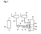
- FIG. 1 shows the schematic diagram of a fuel injection system according to the present Invention.
- the fuel injection system of an internal combustion engine 18 operating with bi-fuel comprises of a liquid fuel tank 19 and a gas fuel tank 11.
- the liquid fuel tank 19 storing the liquid fuel such as gasoline has a fuel supply path 20.
- the liquid fuel is supplied through the fuel supply path 20, to a liquid fuel injection valve 21.
- one liquid fuel injection valve is shown as exemplary. However, with the most of the vehicles with internal combustion engine have several liquid fuel injection valves, particularly four injection valves, are intended to supply an appropriate number of combustion chambers with the liquid fuel.
- the fuel injection valve 21 ejects the liquid fuel to the internal combustion engine 18.
- the gas fuel tank 11 is a high pressure tank and has a fuel supply path 12.
- a high pressure regulator 13 is provided along the fuel supply path 12 to regulate the pressure of gas fuel along the fuel path 12.
- a shut off valve 14 is provided along the fuel supply path 12. The shut off valve 14 when closed prevents the flow of gas fuel from the gas fuel tank 11 to the combustion engine 18.
- Sensing units such as pressure sensing unit 15 and temperature sensing unit 16 are provided to measure the pressure and temperature of the gas fuel entering the plurality of gas fuel injection valves (17a- 17d).
- Sensing units such as pressure sensing unit 15 and temperature sensing unit 16 are provided to measure the pressure and temperature of the gas fuel entering the plurality of gas fuel injection valves (17a- 17d).
- four injectors are shown as exemplary. However, with the most of the vehicles with internal combustion engine have several injection valves, particularly 4 injection valves, are intended to supply an appropriate number of combustion chambers with the gas fuel.
- the sensing units (15, 16) are provided along the fuel supply path 12 between the shut off valve 14 and the fuel injection valves (17a- 17d).
- An electronic control unit 22 that which is not shown in the figure as connected to the other components of the gas fuel injection system regulates the operation of the gas injection valves controls the functions of the components of the fuel injection system and reads the data of the sensing units.
- the gas fuel or the compressed gas is supplied to the internal combustion engine by gas fuel injection valves.
- Each gas fuel injection valve has a sealing seat
- the sealing seat of the gas fuel injection valve can be made from elastomeric material or any other material such as steel.
- the sealing seat is compressed when the valve is closed and returns to its original shape when the valve is opened again.
- gas fuel injection valves do not open reliably.
- gas fuel contains small quantities of oil that cannot be removed completely by a filter. During cold start of an engine, these oils which have low viscosity form a residue on the sealing seat. This increases the force required to open the valves. Further force is needed to open the valves because a very high pressure is developed across the gas fuel injection valves.
- the above problems lead to misfiring and delay in engine start, if started with gas fuel. If it is possible to reduce the pressure of the gas fuel the overall force that is needed to open the valves can also reduced.
- the invention discloses a method explaining how the pressure of the gas fuel is reduced and how the valves are opened in a predetermined pattern to reduce the problem of stiction and in turn to open the gas fuel injection valves reliably against the force exerted by the gas fuel during normal operation which means when operated on gas fuel.
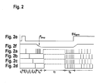
- Figure 2 shows the graphical representation of the operation of the fuel injection valve in a gas fuel injection system when an engine is cranked during a cold start.
- Fig 2e shows the operating signal of the electronic control unit for the shut off valve 14 (high signal: shut off valve is open; low signal: shut off valve is closed) that regulates the supply of gas fuel to the gas fuel injection valves (17a-17d) according to the present invention.
- the fig 2f shows the pressure characteristic in a gas fuel injection system.
- the fig 2a-2d shows the operating signal of the electronic control unit of the gas fuel injection valves (17a-17d) (high signal: valve is open; low signal: valve is closed)
- the engine is started with liquid fuel supplied from the tank 19.
- the shut off valve 14 is opened at t 0 and is closed at t 1 so that supply of gas fuel is stopped.
- the vehicle is continued to be operated in liquid fuel, since opening of the shut off valve without opening the gas fuel injection valves does not supply gas fuel to the engine.
- This invention also holds well if the shutoff valve is closed and then followed by engine start In order to reduce the pressure across the valves, at least one gas fuel injection valve that opens among the plurality of gas fuel injection valves has to be detected.
- the gas fuel injection valve 17a is tried to open at t 2 . If the valve 17a does not open then the gas fuel injection valve 17b is tried to open at t3.
- the process of detecting a valve that opens is continued until a gas fuel injection that opens is detected.
- the gas fuel injection valves 17a, 17b, 17c does not open for the time t 2 , t 3 , t 4 .
- the gas fuel injection valve 17d is detected to be opening at t 5 as shown in Fig 2d .
- the valve 17d is detected to be opening at t 5 because the pressure as shown in figure 2f is reduced by a small amount.
- the shutoff valve is opened for a short while in the beginning because shortly from the normal operation the pressure drop caused by opening the valve 17d is significant.
- the valve that is detected to be opening is opened and closed slowly such that the pressure across the valve is reduced gradually and at same time the amount of liquid fuel is also reduced by an amount of liquid fuel that is equivalent to the amount of gas fuel injected by the valve that opens.
- the opening of the valve reduces the pressure across all valves.
- the pressure P drop as shown in fig 2f shows the gradual decrease of pressure across the valve. As a result the force across the valves is reduced and allows the valves to be opened reliably.
- the gas fuel injection valves have electromagnetic coils. These electromagnetic coils have a resistance and when the coils are energized by a current flow the gas fuels injection valves are heated. In order to stabilise the operation of the gas fuel injection valves the valves are then set to rapid movement at t S for a predetermined frequency. After the rapid movement the shut off valve is opened SV open again. As the shut off is opened, now the gas fuel injection valves are operated in normal mode that is the supply of gas fuel injection is increased and the supply of liquid fuel is decreased.
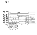
- Figure 3 shows the graphical representation of the operation of the fuel injection valve in a gas fuel injection system when an engine is cranked during a cold start
- Fig 3e shows the operating signal of the electronic control unit for the shut off valve 14 (high signal: shut off valve is open; low signal: shut off valve is closed) that regulates the supply of gas fuel to the gas fuel injection valves (17a-17d) according to the present invention.
- the fig 3f shows the pressure characteristic in a gas fuel injection system.
- the fig 3a-3d shows the operating signal of the electronic control unit of the gas fuel injection valves (17a-17d) (high signal: valve is open; low signal: valve is closed).
- the engine is started with liquid fuel supplied from the tank 19.
- the shut off valve 14 is opened at t 10 and is closed at t 11 so that supply of gas fuel is stopped.
- the vehicle is continued to be operated in liquid fuel, since opening of the shut off valve without opening the gas fuel injection valves does not supply gas fuel to the engine.
- This invention according to this embodiment also holds well if the shutoff valve is closed and then followed by engine start.
- the gas fuel injection valves are operated in a set pattern such that the gas fuel injection valve 17a as shown in fig 3a , is operated at t 12 , similarly the gas fuel injection valve 17b, 17c, 17d are operated at t 13 , t 14 and t 15 as shown in fig 3b, fig 3c and fig 3d .
- the gas fuel injection valve (17a-17d) are continued to be operated at t 16 -t 24 as shown in fig 3a-3d such that a small amount of gas fuel is injected until a low pressure P LOW is detected.
- the amount of gas fuel is small in the sense that the equivalent of liquid fuel is less than 15% of the equivalent amount of liquid fuel.
- This invention of performing a preset operation of the gas injection valve prior to running the internal combustion engine in gas fuel, improves the performance of the gas fuel injection valves.
- the present invention overcomes the problem of stiction of the sealing seat of gas fuel injection valves during cold start and enables efficient operation of the gas fuel injection valves without any delay and inturn improves the overall efficiency of the internal combustion engine.
- the exhaust emission is also controlled efficiently.
- the present invention eliminates the need for any external heating elements to warm up the gas fuel injection valves during cold start. Therefore the cost involved is also reduced and the time involved in mounting additional mechanical components is reduced.
Landscapes
- Engineering & Computer Science (AREA)
- Chemical & Material Sciences (AREA)
- Combustion & Propulsion (AREA)
- Mechanical Engineering (AREA)
- General Engineering & Computer Science (AREA)
- Oil, Petroleum & Natural Gas (AREA)
- Chemical Kinetics & Catalysis (AREA)
- General Chemical & Material Sciences (AREA)
- Output Control And Ontrol Of Special Type Engine (AREA)
- Electrical Control Of Air Or Fuel Supplied To Internal-Combustion Engine (AREA)
- Fuel-Injection Apparatus (AREA)
Priority Applications (5)
| Application Number | Priority Date | Filing Date | Title |
|---|---|---|---|
| EP07001852.8A EP1950409B1 (fr) | 2007-01-29 | 2007-01-29 | Procédé et appareil pour le fonctionnement d'un système à injection de gaz d'un moteur à combustion interne fonctionnant au combustible gazeux et au combustible liquide |
| RU2009132404/06A RU2464439C2 (ru) | 2007-01-29 | 2008-01-18 | Способ и устройство для управления системой впрыска газа в двигатель внутреннего сгорания, работающий на жидком и газообразном топливах |
| US12/308,634 US8560212B2 (en) | 2007-01-29 | 2008-01-18 | Method and device for operating a gas injection system of a gas fuel and a liquid fuel operated internal combustion engine |
| PCT/EP2008/050586 WO2008092761A1 (fr) | 2007-01-29 | 2008-01-18 | Procédé et dispositif pour actionner un système d'injection de gaz d'un moteur à combustion interne actionné avec un combustible gazeux et un combustible liquide |
| CN2008800033099A CN101595296B (zh) | 2007-01-29 | 2008-01-18 | 用于气体燃料和液体燃料工作的内燃机的气体喷射系统运行的方法及设备 |
Applications Claiming Priority (1)
| Application Number | Priority Date | Filing Date | Title |
|---|---|---|---|
| EP07001852.8A EP1950409B1 (fr) | 2007-01-29 | 2007-01-29 | Procédé et appareil pour le fonctionnement d'un système à injection de gaz d'un moteur à combustion interne fonctionnant au combustible gazeux et au combustible liquide |
Publications (3)
| Publication Number | Publication Date |
|---|---|
| EP1950409A2 true EP1950409A2 (fr) | 2008-07-30 |
| EP1950409A3 EP1950409A3 (fr) | 2014-04-09 |
| EP1950409B1 EP1950409B1 (fr) | 2015-12-02 |
Family
ID=38337676
Family Applications (1)
| Application Number | Title | Priority Date | Filing Date |
|---|---|---|---|
| EP07001852.8A Not-in-force EP1950409B1 (fr) | 2007-01-29 | 2007-01-29 | Procédé et appareil pour le fonctionnement d'un système à injection de gaz d'un moteur à combustion interne fonctionnant au combustible gazeux et au combustible liquide |
Country Status (5)
| Country | Link |
|---|---|
| US (1) | US8560212B2 (fr) |
| EP (1) | EP1950409B1 (fr) |
| CN (1) | CN101595296B (fr) |
| RU (1) | RU2464439C2 (fr) |
| WO (1) | WO2008092761A1 (fr) |
Cited By (1)
| Publication number | Priority date | Publication date | Assignee | Title |
|---|---|---|---|---|
| EP2549092A4 (fr) * | 2010-03-19 | 2014-01-15 | Keihin Corp | Dispositif de diagnostic de défaillance de soupape d'arrêt et système d'apport de carburant |
Families Citing this family (19)
| Publication number | Priority date | Publication date | Assignee | Title |
|---|---|---|---|---|
| US7739985B2 (en) * | 2006-03-23 | 2010-06-22 | Lonox Engine Company, Inc. | Internal combustion water injection engine |
| IT1399312B1 (it) * | 2010-04-07 | 2013-04-16 | Magneti Marelli Spa | Metodo di controllo di un iniettore elettromagnetico di carburante |
| US9567918B2 (en) | 2010-05-10 | 2017-02-14 | Go Natural Cng, Llc | Bi-fuel control systems for automotive vehicles and related methods |
| JP5416676B2 (ja) * | 2010-10-19 | 2014-02-12 | 川崎重工業株式会社 | ガスエンジンの燃料ガス供給システム |
| CN102434343B (zh) * | 2011-09-30 | 2013-06-12 | 辽宁科技大学 | 褐煤甲醇煤浆燃料在压缩式内燃机中富氧燃烧的方法 |
| US9422899B2 (en) | 2011-10-24 | 2016-08-23 | Caterpillar Inc. | Dual fuel injector with hydraulic lock seal and liquid leak purge strategy |
| US8997720B2 (en) | 2011-12-23 | 2015-04-07 | Caterpillar Inc. | Dual fuel injector with crossover valve |
| RU2504679C2 (ru) * | 2012-02-08 | 2014-01-20 | Федеральное государственное бюджетное образовательное учреждение высшего профессионального образования "Южно-Российский государственный университет экономики и сервиса" (ФГБОУ ВПО "ЮРГУЭС") | Система управления двухтопливным двигателем |
| JP5827587B2 (ja) | 2012-03-27 | 2015-12-02 | 株式会社ケーヒン | 燃料噴射システム |
| JP5856933B2 (ja) * | 2012-09-13 | 2016-02-10 | 愛三工業株式会社 | 内燃機関の制御装置 |
| US9243588B2 (en) * | 2012-09-20 | 2016-01-26 | Ford Global Technologies, Llc | Variable pressure gaseous fuel regulator |
| US9359963B2 (en) * | 2012-09-20 | 2016-06-07 | Ford Global Technologies, Llc | Gaseous fuel rail depressurization during inactive injector conditions |
| US9644556B2 (en) * | 2013-05-31 | 2017-05-09 | Ford Global Technologies, Llc | Gaseous fuel injector activation |
| US9752520B2 (en) | 2013-05-31 | 2017-09-05 | Ford Global Technologies, Llc | Gaseous fuel injector activation |
| BR112016003574B1 (pt) * | 2013-08-20 | 2021-10-13 | Snecma | Sistema de injeção de combustível, método de injeção de combustível, produto de programa de computador e mídia de armazenamento |
| DE102016219015A1 (de) | 2016-09-30 | 2018-04-05 | Robert Bosch Gmbh | Verbesserung des Kaltstartverhaltens von Verbrennungsmotoren |
| DE102016224682A1 (de) | 2016-12-12 | 2018-06-14 | Robert Bosch Gmbh | Verfahren zur Erwärmung eines Gasventils, insbesondere eines Kraftstoffinjektors |
| US11105278B2 (en) * | 2017-02-03 | 2021-08-31 | Caterpillar Inc. | Dual fuel cylinder deactivation control system and method |
| CN108979875A (zh) * | 2018-08-15 | 2018-12-11 | 奇瑞汽车股份有限公司 | 一种提升喷气嘴低温工作性能的方法 |
Family Cites Families (11)
| Publication number | Priority date | Publication date | Assignee | Title |
|---|---|---|---|---|
| SU1629586A1 (ru) | 1988-05-05 | 1991-02-23 | Восточно-Сибирский Филиал Научно-Исследовательского Института Автомобильного Транспорта | Двухтопливна система питани дизел |
| EP0558591A4 (en) * | 1990-11-20 | 1993-12-01 | Biocom Pty. Ltd. | A dual fuel injection system and a method of controlling such a system |
| RU2136933C1 (ru) * | 1998-03-26 | 1999-09-10 | Общество с ограниченной ответственностью "НТЦ Авангард" | Способ управления двигателем внутреннего сгорания, работающим на основном и альтернативном топливе, и система управления, реализующая этот способ |
| JP3949348B2 (ja) * | 2000-04-20 | 2007-07-25 | 本田技研工業株式会社 | ガス燃料供給装置 |
| US6568379B2 (en) * | 2001-06-25 | 2003-05-27 | General Motors Corporation | Method of gasoline assisted gaseous fuel engine starting |
| ATE440210T1 (de) * | 2001-12-25 | 2009-09-15 | Niigata Power Systems Co Ltd | Zweistoffmotor |
| DE10241444A1 (de) * | 2002-09-06 | 2004-03-18 | Daimlerchrysler Ag | Brennstoffzufuhrvorrichtung einer Brennkraftmaschine |
| DE102005012940A1 (de) * | 2005-03-21 | 2006-09-28 | Robert Bosch Gmbh | Kraftstoffeinspritzeinrichtung für eine Brennkraftmaschine |
| JP4424615B2 (ja) * | 2005-09-28 | 2010-03-03 | 本田技研工業株式会社 | ガス燃料供給装置 |
| DE102006025857A1 (de) * | 2006-06-02 | 2007-12-06 | GM Global Technology Operations, Inc., Detroit | Verfahren zum Betrieb einer Brennkraftmaschinenanordnung |
| KR101049215B1 (ko) * | 2008-06-04 | 2011-07-15 | 혼다 기켄 고교 가부시키가이샤 | 가스 엔진의 연료 공급 장치 |
-
2007
- 2007-01-29 EP EP07001852.8A patent/EP1950409B1/fr not_active Not-in-force
-
2008
- 2008-01-18 WO PCT/EP2008/050586 patent/WO2008092761A1/fr not_active Ceased
- 2008-01-18 US US12/308,634 patent/US8560212B2/en not_active Expired - Fee Related
- 2008-01-18 CN CN2008800033099A patent/CN101595296B/zh not_active Expired - Fee Related
- 2008-01-18 RU RU2009132404/06A patent/RU2464439C2/ru active
Cited By (2)
| Publication number | Priority date | Publication date | Assignee | Title |
|---|---|---|---|---|
| EP2549092A4 (fr) * | 2010-03-19 | 2014-01-15 | Keihin Corp | Dispositif de diagnostic de défaillance de soupape d'arrêt et système d'apport de carburant |
| US8967123B2 (en) | 2010-03-19 | 2015-03-03 | Keihin Corporation | Shut-off valve fault diagnosis device and fuel supply system |
Also Published As
| Publication number | Publication date |
|---|---|
| WO2008092761A1 (fr) | 2008-08-07 |
| RU2464439C2 (ru) | 2012-10-20 |
| EP1950409A3 (fr) | 2014-04-09 |
| EP1950409B1 (fr) | 2015-12-02 |
| RU2009132404A (ru) | 2011-03-10 |
| US8560212B2 (en) | 2013-10-15 |
| CN101595296A (zh) | 2009-12-02 |
| US20100299047A1 (en) | 2010-11-25 |
| CN101595296B (zh) | 2012-03-21 |
Similar Documents
| Publication | Publication Date | Title |
|---|---|---|
| EP1950409B1 (fr) | Procédé et appareil pour le fonctionnement d'un système à injection de gaz d'un moteur à combustion interne fonctionnant au combustible gazeux et au combustible liquide | |
| US7661409B2 (en) | Operating method and device for a gas-operated internal combustion engine | |
| EP2787200B1 (fr) | Dispositif de commande de la fourniture de carburant pour moteur à combustion interne bicarburant et procédé de commutation du carburant dans un moteur à combustion interne bicarburant | |
| CN101403346A (zh) | 缺陷喷射探测装置和具有该装置的燃料喷射系统 | |
| EP2029869B1 (fr) | Moteur à combustion interne bivalent et procédé de fonctionnement d'un moteur à combustion interne bivalent | |
| EP2071158A1 (fr) | Dispositif pour l'injection de gaz dans un moteur à combustion, ensemble de soupapes d'injection de gaz, procédé pour commander les soupapes d'injection de gaz | |
| AU2006201749B2 (en) | Liquefied Petroleum Gas Injection (LPI) System, and Method for Preventing Gas Leakage and Poor Starting Performance using the Same | |
| JP2009539022A (ja) | Lpiシステムが装着されたlpg車両の燃料供給方法及び装置 | |
| WO2002086302A1 (fr) | Systeme et appareil comprenant un dispositif de diagnostic integre et procedes permettant d'ameliorer l'efficacite en fonctionnement et la durabilite des moteurs a combustion par compression | |
| AU2012358130A1 (en) | Method and device for controlling the fuel supply of an internal combustion engine operated with liquefied gas | |
| US7275522B2 (en) | Method and apparatus for controlling a valve, and method and apparatus for controlling a pump-nozzle apparatus with the valve | |
| US9739230B2 (en) | Method of operating a fuel injector | |
| US20240219263A1 (en) | Method of determining a hydraulic timing of a fuel injector | |
| US7974764B2 (en) | Procedure for the reduction of the torque of an internal combustion engine | |
| US12338778B2 (en) | Method of operating a fuel injection system | |
| KR20020089534A (ko) | 특히 자동차 엔진용 연료 공급 시스템 작동 방법 | |
| EP1990523A2 (fr) | Moteur à combustion interne et procédé de fonctionnement d'un moteur à combustion interne | |
| EP2233724A1 (fr) | Unité de contrôle électronique pour commander un ensemble d'injecteurs à carburant | |
| KR100749244B1 (ko) | 엘피아이 차량의 연료 공급 장치의 제어 방법 | |
| KR100749242B1 (ko) | 엘피아이 차량의 연료 공급 장치의 제어 방법 | |
| KR100672193B1 (ko) | 엘피아이 차량의 연료 제어 장치 | |
| EP2077381A1 (fr) | Dispositif pour l'alimentation en carburant d'un moteur à combustion, procédé pour le fonctionnement dudit dispositif pour contrôler le fonctionnement d'un moteur à combustion | |
| KR100749255B1 (ko) | 엘피아이 차량의 연료펌프 제어 방법 | |
| Casacci et al. | 5 th Generation Electronic Gas Injection Control System | |
| JP2021080891A (ja) | バイフューエル車の燃料噴射装置 |
Legal Events
| Date | Code | Title | Description |
|---|---|---|---|
| PUAI | Public reference made under article 153(3) epc to a published international application that has entered the european phase |
Free format text: ORIGINAL CODE: 0009012 |
|
| AK | Designated contracting states |
Kind code of ref document: A2 Designated state(s): AT BE BG CH CY CZ DE DK EE ES FI FR GB GR HU IE IS IT LI LT LU LV MC NL PL PT RO SE SI SK TR |
|
| AX | Request for extension of the european patent |
Extension state: AL BA HR MK RS |
|
| PUAL | Search report despatched |
Free format text: ORIGINAL CODE: 0009013 |
|
| AK | Designated contracting states |
Kind code of ref document: A3 Designated state(s): AT BE BG CH CY CZ DE DK EE ES FI FR GB GR HU IE IS IT LI LT LU LV MC NL PL PT RO SE SI SK TR |
|
| AX | Request for extension of the european patent |
Extension state: AL BA HR MK RS |
|
| RIC1 | Information provided on ipc code assigned before grant |
Ipc: F02D 19/06 20060101ALI20140306BHEP Ipc: F02M 43/00 20060101AFI20140306BHEP |
|
| 17P | Request for examination filed |
Effective date: 20141009 |
|
| RBV | Designated contracting states (corrected) |
Designated state(s): AT BE BG CH CY CZ DE DK EE ES FI FR GB GR HU IE IS IT LI LT LU LV MC NL PL PT RO SE SI SK TR |
|
| AKX | Designation fees paid |
Designated state(s): AT BE BG CH CY CZ DE DK EE ES FI FR GB GR HU IE IS IT LI LT LU LV MC NL PL PT RO SE SI SK TR |
|
| AXX | Extension fees paid |
Extension state: MK Extension state: RS Extension state: AL Extension state: BA Extension state: HR |
|
| 17Q | First examination report despatched |
Effective date: 20150119 |
|
| REG | Reference to a national code |
Ref country code: DE Ref legal event code: R079 Ref document number: 602007044059 Country of ref document: DE Free format text: PREVIOUS MAIN CLASS: F02M0043000000 Ipc: F02M0021020000 |
|
| GRAP | Despatch of communication of intention to grant a patent |
Free format text: ORIGINAL CODE: EPIDOSNIGR1 |
|
| RIC1 | Information provided on ipc code assigned before grant |
Ipc: F02D 19/06 20060101ALI20150529BHEP Ipc: F02D 19/02 20060101ALI20150529BHEP Ipc: F02M 43/00 20060101ALI20150529BHEP Ipc: F02M 21/02 20060101AFI20150529BHEP |
|
| INTG | Intention to grant announced |
Effective date: 20150617 |
|
| GRAS | Grant fee paid |
Free format text: ORIGINAL CODE: EPIDOSNIGR3 |
|
| GRAA | (expected) grant |
Free format text: ORIGINAL CODE: 0009210 |
|
| AK | Designated contracting states |
Kind code of ref document: B1 Designated state(s): AT BE BG CH CY CZ DE DK EE ES FI FR GB GR HU IE IS IT LI LT LU LV MC NL PL PT RO SE SI SK TR |
|
| REG | Reference to a national code |
Ref country code: GB Ref legal event code: FG4D |
|
| REG | Reference to a national code |
Ref country code: AT Ref legal event code: REF Ref document number: 763748 Country of ref document: AT Kind code of ref document: T Effective date: 20151215 Ref country code: CH Ref legal event code: EP |
|
| REG | Reference to a national code |
Ref country code: IE Ref legal event code: FG4D |
|
| REG | Reference to a national code |
Ref country code: DE Ref legal event code: R096 Ref document number: 602007044059 Country of ref document: DE |
|
| REG | Reference to a national code |
Ref country code: NL Ref legal event code: MP Effective date: 20160302 |
|
| REG | Reference to a national code |
Ref country code: LT Ref legal event code: MG4D |
|
| REG | Reference to a national code |
Ref country code: AT Ref legal event code: MK05 Ref document number: 763748 Country of ref document: AT Kind code of ref document: T Effective date: 20151202 |
|
| PG25 | Lapsed in a contracting state [announced via postgrant information from national office to epo] |
Ref country code: ES Free format text: LAPSE BECAUSE OF FAILURE TO SUBMIT A TRANSLATION OF THE DESCRIPTION OR TO PAY THE FEE WITHIN THE PRESCRIBED TIME-LIMIT Effective date: 20151202 Ref country code: LT Free format text: LAPSE BECAUSE OF FAILURE TO SUBMIT A TRANSLATION OF THE DESCRIPTION OR TO PAY THE FEE WITHIN THE PRESCRIBED TIME-LIMIT Effective date: 20151202 |
|
| PG25 | Lapsed in a contracting state [announced via postgrant information from national office to epo] |
Ref country code: AT Free format text: LAPSE BECAUSE OF FAILURE TO SUBMIT A TRANSLATION OF THE DESCRIPTION OR TO PAY THE FEE WITHIN THE PRESCRIBED TIME-LIMIT Effective date: 20151202 Ref country code: FI Free format text: LAPSE BECAUSE OF FAILURE TO SUBMIT A TRANSLATION OF THE DESCRIPTION OR TO PAY THE FEE WITHIN THE PRESCRIBED TIME-LIMIT Effective date: 20151202 Ref country code: PL Free format text: LAPSE BECAUSE OF FAILURE TO SUBMIT A TRANSLATION OF THE DESCRIPTION OR TO PAY THE FEE WITHIN THE PRESCRIBED TIME-LIMIT Effective date: 20151202 Ref country code: BE Free format text: LAPSE BECAUSE OF NON-PAYMENT OF DUE FEES Effective date: 20160131 Ref country code: GR Free format text: LAPSE BECAUSE OF FAILURE TO SUBMIT A TRANSLATION OF THE DESCRIPTION OR TO PAY THE FEE WITHIN THE PRESCRIBED TIME-LIMIT Effective date: 20160303 Ref country code: NL Free format text: LAPSE BECAUSE OF FAILURE TO SUBMIT A TRANSLATION OF THE DESCRIPTION OR TO PAY THE FEE WITHIN THE PRESCRIBED TIME-LIMIT Effective date: 20151202 Ref country code: LV Free format text: LAPSE BECAUSE OF FAILURE TO SUBMIT A TRANSLATION OF THE DESCRIPTION OR TO PAY THE FEE WITHIN THE PRESCRIBED TIME-LIMIT Effective date: 20151202 Ref country code: SE Free format text: LAPSE BECAUSE OF FAILURE TO SUBMIT A TRANSLATION OF THE DESCRIPTION OR TO PAY THE FEE WITHIN THE PRESCRIBED TIME-LIMIT Effective date: 20151202 |
|
| PG25 | Lapsed in a contracting state [announced via postgrant information from national office to epo] |
Ref country code: IS Free format text: LAPSE BECAUSE OF FAILURE TO SUBMIT A TRANSLATION OF THE DESCRIPTION OR TO PAY THE FEE WITHIN THE PRESCRIBED TIME-LIMIT Effective date: 20151202 |
|
| PG25 | Lapsed in a contracting state [announced via postgrant information from national office to epo] |
Ref country code: CZ Free format text: LAPSE BECAUSE OF FAILURE TO SUBMIT A TRANSLATION OF THE DESCRIPTION OR TO PAY THE FEE WITHIN THE PRESCRIBED TIME-LIMIT Effective date: 20151202 |
|
| PG25 | Lapsed in a contracting state [announced via postgrant information from national office to epo] |
Ref country code: LU Free format text: LAPSE BECAUSE OF FAILURE TO SUBMIT A TRANSLATION OF THE DESCRIPTION OR TO PAY THE FEE WITHIN THE PRESCRIBED TIME-LIMIT Effective date: 20160129 Ref country code: RO Free format text: LAPSE BECAUSE OF FAILURE TO SUBMIT A TRANSLATION OF THE DESCRIPTION OR TO PAY THE FEE WITHIN THE PRESCRIBED TIME-LIMIT Effective date: 20151202 Ref country code: EE Free format text: LAPSE BECAUSE OF FAILURE TO SUBMIT A TRANSLATION OF THE DESCRIPTION OR TO PAY THE FEE WITHIN THE PRESCRIBED TIME-LIMIT Effective date: 20151202 Ref country code: PT Free format text: LAPSE BECAUSE OF FAILURE TO SUBMIT A TRANSLATION OF THE DESCRIPTION OR TO PAY THE FEE WITHIN THE PRESCRIBED TIME-LIMIT Effective date: 20160404 Ref country code: SK Free format text: LAPSE BECAUSE OF FAILURE TO SUBMIT A TRANSLATION OF THE DESCRIPTION OR TO PAY THE FEE WITHIN THE PRESCRIBED TIME-LIMIT Effective date: 20151202 Ref country code: IS Free format text: LAPSE BECAUSE OF FAILURE TO SUBMIT A TRANSLATION OF THE DESCRIPTION OR TO PAY THE FEE WITHIN THE PRESCRIBED TIME-LIMIT Effective date: 20160402 |
|
| REG | Reference to a national code |
Ref country code: CH Ref legal event code: PL |
|
| REG | Reference to a national code |
Ref country code: DE Ref legal event code: R097 Ref document number: 602007044059 Country of ref document: DE |
|
| PG25 | Lapsed in a contracting state [announced via postgrant information from national office to epo] |
Ref country code: MC Free format text: LAPSE BECAUSE OF FAILURE TO SUBMIT A TRANSLATION OF THE DESCRIPTION OR TO PAY THE FEE WITHIN THE PRESCRIBED TIME-LIMIT Effective date: 20151202 |
|
| PLBE | No opposition filed within time limit |
Free format text: ORIGINAL CODE: 0009261 |
|
| STAA | Information on the status of an ep patent application or granted ep patent |
Free format text: STATUS: NO OPPOSITION FILED WITHIN TIME LIMIT |
|
| REG | Reference to a national code |
Ref country code: FR Ref legal event code: ST Effective date: 20160930 |
|
| PG25 | Lapsed in a contracting state [announced via postgrant information from national office to epo] |
Ref country code: LI Free format text: LAPSE BECAUSE OF NON-PAYMENT OF DUE FEES Effective date: 20160131 Ref country code: CH Free format text: LAPSE BECAUSE OF NON-PAYMENT OF DUE FEES Effective date: 20160131 Ref country code: DK Free format text: LAPSE BECAUSE OF FAILURE TO SUBMIT A TRANSLATION OF THE DESCRIPTION OR TO PAY THE FEE WITHIN THE PRESCRIBED TIME-LIMIT Effective date: 20151202 |
|
| REG | Reference to a national code |
Ref country code: IE Ref legal event code: MM4A |
|
| 26N | No opposition filed |
Effective date: 20160905 |
|
| GBPC | Gb: european patent ceased through non-payment of renewal fee |
Effective date: 20160302 |
|
| PG25 | Lapsed in a contracting state [announced via postgrant information from national office to epo] |
Ref country code: FR Free format text: LAPSE BECAUSE OF NON-PAYMENT OF DUE FEES Effective date: 20160202 Ref country code: SI Free format text: LAPSE BECAUSE OF FAILURE TO SUBMIT A TRANSLATION OF THE DESCRIPTION OR TO PAY THE FEE WITHIN THE PRESCRIBED TIME-LIMIT Effective date: 20151202 |
|
| PG25 | Lapsed in a contracting state [announced via postgrant information from national office to epo] |
Ref country code: BE Free format text: LAPSE BECAUSE OF FAILURE TO SUBMIT A TRANSLATION OF THE DESCRIPTION OR TO PAY THE FEE WITHIN THE PRESCRIBED TIME-LIMIT Effective date: 20151202 |
|
| PG25 | Lapsed in a contracting state [announced via postgrant information from national office to epo] |
Ref country code: IE Free format text: LAPSE BECAUSE OF NON-PAYMENT OF DUE FEES Effective date: 20160129 Ref country code: GB Free format text: LAPSE BECAUSE OF NON-PAYMENT OF DUE FEES Effective date: 20160302 |
|
| PGFP | Annual fee paid to national office [announced via postgrant information from national office to epo] |
Ref country code: IT Payment date: 20170125 Year of fee payment: 11 |
|
| PG25 | Lapsed in a contracting state [announced via postgrant information from national office to epo] |
Ref country code: CY Free format text: LAPSE BECAUSE OF FAILURE TO SUBMIT A TRANSLATION OF THE DESCRIPTION OR TO PAY THE FEE WITHIN THE PRESCRIBED TIME-LIMIT Effective date: 20151202 Ref country code: HU Free format text: LAPSE BECAUSE OF FAILURE TO SUBMIT A TRANSLATION OF THE DESCRIPTION OR TO PAY THE FEE WITHIN THE PRESCRIBED TIME-LIMIT; INVALID AB INITIO Effective date: 20070129 |
|
| PG25 | Lapsed in a contracting state [announced via postgrant information from national office to epo] |
Ref country code: TR Free format text: LAPSE BECAUSE OF FAILURE TO SUBMIT A TRANSLATION OF THE DESCRIPTION OR TO PAY THE FEE WITHIN THE PRESCRIBED TIME-LIMIT Effective date: 20151202 |
|
| PG25 | Lapsed in a contracting state [announced via postgrant information from national office to epo] |
Ref country code: BG Free format text: LAPSE BECAUSE OF FAILURE TO SUBMIT A TRANSLATION OF THE DESCRIPTION OR TO PAY THE FEE WITHIN THE PRESCRIBED TIME-LIMIT Effective date: 20151202 |
|
| PG25 | Lapsed in a contracting state [announced via postgrant information from national office to epo] |
Ref country code: IT Free format text: LAPSE BECAUSE OF NON-PAYMENT OF DUE FEES Effective date: 20180129 |
|
| PGFP | Annual fee paid to national office [announced via postgrant information from national office to epo] |
Ref country code: DE Payment date: 20230324 Year of fee payment: 17 |
|
| REG | Reference to a national code |
Ref country code: DE Ref legal event code: R119 Ref document number: 602007044059 Country of ref document: DE |
|
| PG25 | Lapsed in a contracting state [announced via postgrant information from national office to epo] |
Ref country code: DE Free format text: LAPSE BECAUSE OF NON-PAYMENT OF DUE FEES Effective date: 20240801 |
|
| PG25 | Lapsed in a contracting state [announced via postgrant information from national office to epo] |
Ref country code: DE Free format text: LAPSE BECAUSE OF NON-PAYMENT OF DUE FEES Effective date: 20240801 |