EP1950414A2 - Trennbares Rotorblatt einer Windkraftanlage - Google Patents
Trennbares Rotorblatt einer Windkraftanlage Download PDFInfo
- Publication number
- EP1950414A2 EP1950414A2 EP08150513A EP08150513A EP1950414A2 EP 1950414 A2 EP1950414 A2 EP 1950414A2 EP 08150513 A EP08150513 A EP 08150513A EP 08150513 A EP08150513 A EP 08150513A EP 1950414 A2 EP1950414 A2 EP 1950414A2
- Authority
- EP
- European Patent Office
- Prior art keywords
- blade
- fastener
- hole part
- hole
- separable
- Prior art date
- Legal status (The legal status is an assumption and is not a legal conclusion. Google has not performed a legal analysis and makes no representation as to the accuracy of the status listed.)
- Granted
Links
- 239000004020 conductor Substances 0.000 claims description 11
- 230000002093 peripheral effect Effects 0.000 claims description 3
- 239000002184 metal Substances 0.000 abstract description 12
- 238000010586 diagram Methods 0.000 description 11
- 229920002430 Fibre-reinforced plastic Polymers 0.000 description 8
- 239000011151 fibre-reinforced plastic Substances 0.000 description 8
- 238000005192 partition Methods 0.000 description 6
- 238000000034 method Methods 0.000 description 5
- 238000005516 engineering process Methods 0.000 description 4
- 238000010248 power generation Methods 0.000 description 3
- 238000003466 welding Methods 0.000 description 3
- 239000000463 material Substances 0.000 description 2
- 239000004593 Epoxy Substances 0.000 description 1
- 238000007599 discharging Methods 0.000 description 1
- 230000000694 effects Effects 0.000 description 1
- 238000003754 machining Methods 0.000 description 1
- 239000012811 non-conductive material Substances 0.000 description 1
- 229920001296 polysiloxane Polymers 0.000 description 1
- 229920005989 resin Polymers 0.000 description 1
- 239000011347 resin Substances 0.000 description 1
- 238000010079 rubber tapping Methods 0.000 description 1
- 239000000565 sealant Substances 0.000 description 1
Images


Classifications
-
- F—MECHANICAL ENGINEERING; LIGHTING; HEATING; WEAPONS; BLASTING
- F03—MACHINES OR ENGINES FOR LIQUIDS; WIND, SPRING, OR WEIGHT MOTORS; PRODUCING MECHANICAL POWER OR A REACTIVE PROPULSIVE THRUST, NOT OTHERWISE PROVIDED FOR
- F03D—WIND MOTORS
- F03D1/00—Wind motors with rotation axis substantially parallel to the air flow entering the rotor
- F03D1/06—Rotors
- F03D1/065—Rotors characterised by their construction elements
- F03D1/0675—Rotors characterised by their construction elements of the blades
-
- F—MECHANICAL ENGINEERING; LIGHTING; HEATING; WEAPONS; BLASTING
- F03—MACHINES OR ENGINES FOR LIQUIDS; WIND, SPRING, OR WEIGHT MOTORS; PRODUCING MECHANICAL POWER OR A REACTIVE PROPULSIVE THRUST, NOT OTHERWISE PROVIDED FOR
- F03D—WIND MOTORS
- F03D80/00—Details, components or accessories not provided for in groups F03D1/00 - F03D17/00
- F03D80/30—Lightning protection
-
- F—MECHANICAL ENGINEERING; LIGHTING; HEATING; WEAPONS; BLASTING
- F05—INDEXING SCHEMES RELATING TO ENGINES OR PUMPS IN VARIOUS SUBCLASSES OF CLASSES F01-F04
- F05B—INDEXING SCHEME RELATING TO WIND, SPRING, WEIGHT, INERTIA OR LIKE MOTORS, TO MACHINES OR ENGINES FOR LIQUIDS COVERED BY SUBCLASSES F03B, F03D AND F03G
- F05B2230/00—Manufacture
- F05B2230/50—Building or constructing in particular ways
-
- F—MECHANICAL ENGINEERING; LIGHTING; HEATING; WEAPONS; BLASTING
- F05—INDEXING SCHEMES RELATING TO ENGINES OR PUMPS IN VARIOUS SUBCLASSES OF CLASSES F01-F04
- F05B—INDEXING SCHEME RELATING TO WIND, SPRING, WEIGHT, INERTIA OR LIKE MOTORS, TO MACHINES OR ENGINES FOR LIQUIDS COVERED BY SUBCLASSES F03B, F03D AND F03G
- F05B2240/00—Components
- F05B2240/20—Rotors
- F05B2240/30—Characteristics of rotor blades, i.e. of any element transforming dynamic fluid energy to or from rotational energy and being attached to a rotor
- F05B2240/302—Segmented or sectional blades
-
- F—MECHANICAL ENGINEERING; LIGHTING; HEATING; WEAPONS; BLASTING
- F05—INDEXING SCHEMES RELATING TO ENGINES OR PUMPS IN VARIOUS SUBCLASSES OF CLASSES F01-F04
- F05B—INDEXING SCHEME RELATING TO WIND, SPRING, WEIGHT, INERTIA OR LIKE MOTORS, TO MACHINES OR ENGINES FOR LIQUIDS COVERED BY SUBCLASSES F03B, F03D AND F03G
- F05B2260/00—Function
- F05B2260/30—Retaining components in desired mutual position
- F05B2260/301—Retaining bolts or nuts
-
- Y—GENERAL TAGGING OF NEW TECHNOLOGICAL DEVELOPMENTS; GENERAL TAGGING OF CROSS-SECTIONAL TECHNOLOGIES SPANNING OVER SEVERAL SECTIONS OF THE IPC; TECHNICAL SUBJECTS COVERED BY FORMER USPC CROSS-REFERENCE ART COLLECTIONS [XRACs] AND DIGESTS
- Y02—TECHNOLOGIES OR APPLICATIONS FOR MITIGATION OR ADAPTATION AGAINST CLIMATE CHANGE
- Y02E—REDUCTION OF GREENHOUSE GAS [GHG] EMISSIONS, RELATED TO ENERGY GENERATION, TRANSMISSION OR DISTRIBUTION
- Y02E10/00—Energy generation through renewable energy sources
- Y02E10/70—Wind energy
- Y02E10/72—Wind turbines with rotation axis in wind direction
-
- Y—GENERAL TAGGING OF NEW TECHNOLOGICAL DEVELOPMENTS; GENERAL TAGGING OF CROSS-SECTIONAL TECHNOLOGIES SPANNING OVER SEVERAL SECTIONS OF THE IPC; TECHNICAL SUBJECTS COVERED BY FORMER USPC CROSS-REFERENCE ART COLLECTIONS [XRACs] AND DIGESTS
- Y02—TECHNOLOGIES OR APPLICATIONS FOR MITIGATION OR ADAPTATION AGAINST CLIMATE CHANGE
- Y02P—CLIMATE CHANGE MITIGATION TECHNOLOGIES IN THE PRODUCTION OR PROCESSING OF GOODS
- Y02P70/00—Climate change mitigation technologies in the production process for final industrial or consumer products
- Y02P70/50—Manufacturing or production processes characterised by the final manufactured product
Definitions
- the present invention relates to the fastening of separable blades for wind turbines, and the lightning protection structures thereof.
- An ordinary horizontal axis wind turbine is comprised by a rotor whereon at least two or more blades are radially attached from a hub, a nacelle that is connected to the hub and axially supports this rotor through a main shaft that is extended in an approximate horizontal direction, and a tower that is installed in an approximate vertical direction and supports the nacelle in a yaw rotatable state.
- FRP fiber-reinforced plastics
- part blades which are partitioned in the longitudinal direction, are connected in series to form the whole.
- a connecting member is provided in the vicinity of a connecting section between part blades that are connected in series together, where the part blades and the connecting member are secured together with bolts.
- blades comprising a non-conductive material such as FRP differ from metallic blades and if struck by lightning, there is danger that the lightning bolt current will not be able to dissipate to ground resulting in damage.
- FRP non-conductive material
- the present invention was the result of contemplation on the problems with the prior art described above, and the object thereof is to provide a light and economical separable blade for a wind turbine that is also equipped with a lightning protection function.
- a first aspect of the present invention is a separable blade for a wind turbine wherein non-conductive part blades are connected in series in the longitudinal direction to assemble the blade as a whole, having:
- a third aspect of the present invention is a separable blade for a wind turbine as set forth in the second aspect wherein a cover member is provided for covering an opening that opens at the blade surface of either the first hole part or the third hole part, and the fastener of the other hole part (that is, the first fastener for the first hole part or the second fastener for the third hole part) is exposed at the blade surface.
- a fourth aspect of the present invention is a separable blade for a wind turbine as set forth in the second or third aspect, wherein the third fastener is a rod member having an external threaded portion on a tip portion thereof, wherein the fastener comprises a nut that threads onto the external threaded portion and that is housed within either the first hole part or the third hole part, and a jack bolt that screws onto the peripheral part of the nut to jack up the nut, wherein the lightning discharge conductive wire is connected to the jack bolt.
- the third fastener is a rod member having an external threaded portion on a tip portion thereof, wherein the fastener comprises a nut that threads onto the external threaded portion and that is housed within either the first hole part or the third hole part, and a jack bolt that screws onto the peripheral part of the nut to jack up the nut, wherein the lightning discharge conductive wire is connected to the jack bolt.
- a fifth aspect of the present invention is a separable blade for a wind turbine as set forth in the fourth aspect, wherein the cover member is provided for covering the opening of the hole part that opens at the blade surface, the hole part being either the first hole part or the third hole part that houses the nut.
- a sixth aspect of the present invention is a separable blade for a wind turbine as set forth in any of the first through fifth aspects, further comprising a lightning receptor part on a blade tip part.
- a seventh aspect of the present invention is a separable blade for a wind turbine as set forth in any of the first through sixth aspects, wherein the lightning discharge conductive wire is connected to a plurality of the fasteners that are provided.
- a portion of the fastener is exposed at the blade surface as a lightning receptor part, and is connected to a lightning discharge conductive wire in a blade inner portion.
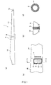
- Fig. 1 (a) is an overall view of a separable blade as set forth in one embodiment of the present invention.
- Fig. 1 (b) is a detail view of part A;
- Fig. 1 (c) is a detail view of part B;
- Fig. 1 (d) is an expanded view of the exposed surface of the first fastener.
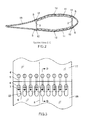
- Fig. 2 is a cross-sectional diagram along section C-C shown in Fig. 1 (b) .
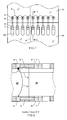
- Fig. 3 is a plan view schematic diagram of the connector part, and
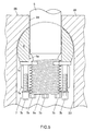
- Fig. 4 is a cross-sectional diagram along section D-D.
- the separable blade 1 of the present embodiment is structured from a first part blade 1T on the blade tip side, and a second part blade 1R on the blade root side.
- the part blades 1T and 1 R are made from a non-electrically conductive material such as FRP, and, as shown in Fig. 2 , have a structure wherein top and bottom outer planes are held in a front beam 2 and a back beam 3.
- the detailed connecting structure in the second part blade 1R on the blade root side is shown in Fig. 5
- the detailed connecting structure in the first part blade 1T on the blade tip side is shown in Fig. 6 .
- a hole that passes through in the direction of thickness of the panels, another hole that is communicated with the other hole and opens at the connecting surface are formed.
- a first hole part 21 that is open on the blade surface and a second hole part 22 that is communicated with first hole part 21 and that is open on the blade root side end surface 25 of the first part blade 1T are formed in the blade root side end portion of the first part blade 1T.
- a third hole part 23 that is open on the blade surface and a fourth hole part 24 that is communicated with the third hole part 23 and that is open on the blade tip side end surface 26 of the second part blade 1R and that continuously communicates with the second hole part 22 are formed in the blade tip side end portion of the second part blade 1R.
- the first fastener 4 is inserted into the first hole part 21.
- the first fastener 4 is a cylindrical metal component, and a horizontal hole 4a, wherein internal threads are cut, is open in the center of the periphery thereof.
- the first hole part 21 has a diameter of a size that is able to essentially accommodate the first fastener 4 without a gap.
- the first hole part 21 may be an opening wherein there is a gap with the first fastener 4 on the blade tip end side, but because there will be the need to fill the gap later, preferably the design is such that, if possible, there will be no gap.
- the third fastener 5 is a metal bolt having external threaded portions 5a and 5b on both ends thereof.
- the second fastener 6 is disposed within the third hole part 23, and the end part of the third fastener 5 having the external threaded portion 5a is inserted into the horizontal hole 6a of the second fastener 6.
- the external threaded portion 5a will protrude to the blade root side from the horizontal hole 6a, as shown in Fig. 5 .
- the third fastener 5 is passed through the second hole part 22 and the fourth opening port 24.
- the third hole part 23 is a long hole, having a cylindrical inner surface, in the end part on the blade tip end side.
- the second fastener 6 is a cylindrical metal component, and a horizontal hole 6a is open in the center of the periphery thereof. Note that a portion of the periphery of the second fastener 6 is formed as a flat surface so as to ensure a seat for the fastener 7.
- the fastener 7 each comprise a nut 7a, a jack bolt 7b, and a washer 7c, all made of metal, and can use off-the-shelf products.
- the jack bolt 7b screws onto the periphery of the nut 7a to jack up relative to the watcher 7c.
- the washer 7c lays against the flat surface that is formed in a portion of the periphery of the second fastener 6.
- a lightning discharge conductive wire 8 is attached to the jack bolt 7b of each of the fasteners 7, and the various fasteners 7 are connected by the lightning discharge conductive wires 8, as shown in Fig. 3 .
- the upper and the lower fasteners 7 and 7 are connected by the lightning discharge conductive wire 13a by installing the lightning discharge conductive wire 13 to at least one jack bolt 7b on each side.
- the lightning discharge conductive wire 9 that extends from the tip lightning receiver part 10 is connected to at least one of the jack bolt 7b. The end portion of the lightning discharge conductive wire 9 extends toward the blade root and comes out the opening at the blade root.
- the jack bolt 7b is screwed in to jack up the nut 7a relative to the washer 7c. That is, a wrench is inserted into the third hole part 23 to fit onto the head of the jack bolt 7b, rotate the jack bolt 7b in the screw-in direction. This causes the first fastener 4 and the second fastener 6 to be tightened in the direction of mutually approaching each other.
- the first fastener 4 interlocks with the first hole part 21, and the second fastener 6 interlocks with the third hole part 23. Consequently, a tensile force is produced on the third fastener 5, and the third fastener 5 fastens tensely the first part blade 1T and the second part blade 1T.
- the lightning discharge conductive wires 8, 9, and 13, which are attached to the jack bolt 7b, are pinched between the head of the jack bolt 7b and the nut 7a, to be connected securely.
- a cover member 11, for covering the opening that opens at the blade surface of the third hole part 23, is attached to the blade surface of the second part blade 1R.
- the cover member 11 is secured to the outer panel of the second part blade 1R by a tapping thread 12.
- the periphery of the cover member 11, the partition parts of the first part blade 1T and the second part blade 1R, and the periphery of the exposed part of the first fastener 4 are caulked with a sealant S made from epoxy or silicone.
- a non-electrically-conductive material such as resin or FRP, or the like, may be used for the material for the cover member 11; an electrically conductive material is not suitable.
- the separable blade 1 as set forth in the present example embodiment is structured as described above, and is attached to the hub of the horizontal axis wind turbine.
- the lightning discharge conductive wire 9 is grounded via the hub, the nacelle, and the tower.
- the lightning discharge conductive wire 9 may extend to the ground, or may be grounded through the use of metal components in the hub, the nacelle, and the tower.
- the exposed parts of the first fastener 4 in the vicinity of the partition part of the blade 1 serve as lightning receptor parts along with the Tip lightning receptor member 10.
- the lightning electrical current that strikes the Tip lightning receptor member 10 escapes to the ground through the lightning discharge conductive wire 9.
- the lightning electrical current that strikes the first fastener 4 escapes to the ground through the fasteners 5, 6, 7 and the lightning discharge conductive wires 8, 9, 13.
- the separable blade 1 As set forth in the present example embodiment, no special member for discharging the lightning is provided in the partition part, and thus the separable blade 1 is light and economical. Because there are no operations for building in a special member to discharge the lightning, the assembly operations are easy, and assembly can be performed in a short time. It possible to design the fasteners that are disposed within the blades so as to have adequate thickness, not only making it possible to ensure adequate fastening strength, but also making it possible to have desirable aerodynamic properties with little effect on the external shape of the blades.
- the end portion (the exposed portion) of the first fastener 4 that is exposed on the blade surface of the first part blade 1T may protrude slightly from the blade surface of the first part blade 1T, or may be flush with the blade surface of the first part blade 1T. Even though having the first fastener 4 protrude from the blade surface will increase the lightning strike rate, doing so will have a negative impact on the aerodynamic properties.
- the height of protrusion of the first fastener 4 from the blade surface should be designed taking this into consideration.
- the second fastener 6 may also be exposed at the blade surface to be a lightning receptor part as well.
- the height of the protrusion of the second fastener 6 from the cover member 11 can be designed as appropriate, and this height can be achieved easily by forming, in the cover member 11, a hole or notch to expose the second fastener 6.
- Both the first fastener 4 and the second fastener 6 may be exposed so as to be lightning receptor parts, or, instead, only one or the other may be exposed to be a lightning receptor part.
- first hole part 21, the second hole part 22, and the first fastener 4 may be provided in the second part blade 1R and the third hole part 23, the fourth hole part 24, the second fastener 6, and the fastener 7 may be provided in the first part blade 1T.
- the embodiment described above was one of a separable blade wherein the blade as a whole was assembled by connecting two part blades 1T and 1R in the lateral direction
- the separable blade may be structured such that the blade as a whole is assembled by connecting, in the lateral direction, three or more part blades.
- the connecting structure with the lightning receptor part as set forth in the present invention may be applied to all of the partition parts, or the connecting structure with the lightning receptor part as set forth in the present invention may be applied to only a portion of the partition parts.
- all of the fasteners 4, 5, 6, and 7 were made from an electrically conductive material, at least the parts of the fasteners that are exposed at the blade surface, and the portions of the parts that are exposed at the blade surface, may be made from an electrically conductive material, and these may be connected within the blade to the lightning discharge conductive wire. If there are adequately strong non-conductive bolts, nuts, or other fasteners, these may be used as desired outside of the lightning discharge path.
- the lightning discharge conductive wire was connected to the jack bolt 7b of the fastener 7
- the lightning discharge conductive wire may be connected to any part of any fastener insofar as there is electrical conductivity with the portion of the fastener that is exposed at the blade surface.
- the following embodiment is useful if the jack bolt 7b is not used, and in other cases.
- FIG. 9 Another embodiment pertaining to the connecting structure between the lightning discharge conductive wire and the fastener is, as shown in Fig. 7 through Fig. 9 , a structure wherein the lightning discharge conductive wires 8, 9, and 13 are connected to the lightning receptor part that is the first fastener 4.
- the connection may be made using a bolt, by welding, or the like. If the connection is made using a bolt, then, as shown in Fig. 9 , for example, a bolt 15 is fastened by screwing into a screw hole 4b that is provided on the inner end of the first fastener 4, through crimp-type terminals 14 that are provided on the lightning discharge conductive wires 8, 9, and 13, to cause the crimp-type terminals 14 to be pressed onto the first fastener 4.
- Each of the first fasteners 4, 4, 4... above and below are provided with screw holes 4b, and the respective lightning discharge conductive wires 8, 9, and 13 can be connected using bolts 15.
- the lightning discharge conductive wires are connected to the second fastener 6.
- a screw hole is provided in the second fastener 6 to connect the lightning discharge conductive wire to the second fastener 6 using a bolt, or the connection is made through welding or through the use of some other method.
- connections between the lightning discharge conductive wires and the fasteners of the part blades may use bolt connections, welding, or other connecting methods, but preferably the method is one which, as far as is possible, does not reduce the strength with which the part blade is secured, and regardless of the method used, the connection should be designed so that there will be no problems in terms of strength.
Landscapes
- Engineering & Computer Science (AREA)
- Life Sciences & Earth Sciences (AREA)
- Sustainable Development (AREA)
- Sustainable Energy (AREA)
- Chemical & Material Sciences (AREA)
- Combustion & Propulsion (AREA)
- Mechanical Engineering (AREA)
- General Engineering & Computer Science (AREA)
- Wind Motors (AREA)
- Elimination Of Static Electricity (AREA)
Applications Claiming Priority (1)
| Application Number | Priority Date | Filing Date | Title |
|---|---|---|---|
| JP2007012504A JP5242920B2 (ja) | 2007-01-23 | 2007-01-23 | 風車用分割翼 |
Publications (3)
| Publication Number | Publication Date |
|---|---|
| EP1950414A2 true EP1950414A2 (de) | 2008-07-30 |
| EP1950414A3 EP1950414A3 (de) | 2012-12-05 |
| EP1950414B1 EP1950414B1 (de) | 2015-09-23 |
Family
ID=39106083
Family Applications (1)
| Application Number | Title | Priority Date | Filing Date |
|---|---|---|---|
| EP08150513.3A Active EP1950414B1 (de) | 2007-01-23 | 2008-01-22 | Trennbares Rotorblatt einer Windkraftanlage |
Country Status (4)
| Country | Link |
|---|---|
| US (1) | US8142157B2 (de) |
| EP (1) | EP1950414B1 (de) |
| JP (1) | JP5242920B2 (de) |
| ES (1) | ES2552546T3 (de) |
Cited By (30)
| Publication number | Priority date | Publication date | Assignee | Title |
|---|---|---|---|---|
| GB2470344A (en) * | 2009-03-17 | 2010-11-24 | Vestas Wind Sys As | Lightning protected hinge for wind turbine components |
| WO2010023299A3 (en) * | 2008-08-31 | 2010-12-16 | Vestas Wind Systems A/S | A sectional blade |
| GB2472460A (en) * | 2009-08-07 | 2011-02-09 | Gurit | Wind or Tidal Turbine Blade having an Attachment |
| WO2011070137A1 (en) * | 2009-12-11 | 2011-06-16 | Vestas Wind Systems A/S | A sectional blade |
| CN102606419A (zh) * | 2012-04-16 | 2012-07-25 | 国电联合动力技术有限公司 | 一种分段式风轮叶片及其连接机构以及安装方法 |
| CN102637233A (zh) * | 2012-04-17 | 2012-08-15 | 西北工业大学 | 一种涡轮叶片伸根段内型参数化建模方法 |
| WO2013083451A1 (de) * | 2011-12-08 | 2013-06-13 | Wobben Properties Gmbh | Rotorblatt und verbindungsvorrichtung |
| WO2013110061A1 (en) * | 2012-01-20 | 2013-07-25 | General Electric Company | Blade extension and rotor blade assembly for wind turbine |
| DE102012111219A1 (de) | 2012-11-21 | 2014-05-22 | Spitzner Engineers GmbH | Windenergieanlagenkomponente |
| EP2243955A3 (de) * | 2009-04-22 | 2014-08-27 | Gamesa Innovation & Technology, S.L. | Blitzschutzsystem für sektionale Windturbineblätter |
| EP2881580A1 (de) * | 2013-12-04 | 2015-06-10 | General Electric Company | Holmanordnung für ein Windturbinenrotorblatt |
| US20150240780A1 (en) * | 2014-02-25 | 2015-08-27 | General Electric Company | Joint assembly for rotor blade segments of a wind turbine |
| WO2016048148A1 (en) * | 2014-09-23 | 2016-03-31 | Viventus Holding B.V. | Segmented wind turbine blade and bushing for use in a wind turbine blade |
| RU2588311C2 (ru) * | 2011-12-08 | 2016-06-27 | Воббен Пропертиз Гмбх | Роторная лопасть и соединительное устройство |
| US9388789B2 (en) | 2009-12-02 | 2016-07-12 | Vestas Wind Systems A/S | Sectional wind turbine blade |
| EP3064768A1 (de) * | 2015-03-04 | 2016-09-07 | Siemens Aktiengesellschaft | Windturbinenrotorblatt und Verfahren zur Montage eines Windturbinenrotorblatts |
| CN106164476A (zh) * | 2014-04-07 | 2016-11-23 | 乌本产权有限公司 | 风能设备的转子叶片 |
| CN106194611A (zh) * | 2015-05-26 | 2016-12-07 | 歌美飒创新技术公司 | 用于风力涡轮机叶片的雷电接收器 |
| US9765756B2 (en) | 2008-05-07 | 2017-09-19 | Vestas Wind Systems A/S | Sectional blade |
| US9797369B2 (en) | 2014-04-11 | 2017-10-24 | Siemens Aktiengesellschaft | Segmented rotor blade with a bolt connection |
| US20180238300A1 (en) * | 2017-02-21 | 2018-08-23 | General Electric Company | Joint Assembly for Rotor Blade Segments of a Wind Turbine |
| EP3524412A1 (de) * | 2018-02-12 | 2019-08-14 | Nordex Energy GmbH | Teilbares windenergieanlagenrotorblatt mit einer blitzschutzeinrichtung und verfahren zur herstellung eines solchen windenergieanlagenrotorblatts |
| WO2019238165A1 (de) * | 2018-06-13 | 2019-12-19 | Klaus Schultes | Anordnung zur zug- bzw. längskrafteinleitung sowie verfahren zur herstellung einer solchen anordnung |
| WO2020084052A1 (en) | 2018-10-25 | 2020-04-30 | Lm Wind Power A/S | Lightning protection for a wind turbine blade |
| WO2020089064A1 (en) * | 2018-10-29 | 2020-05-07 | Blade Dynamics Limited | Access arrangement for a wind turbine blade |
| US11015573B2 (en) | 2016-12-28 | 2021-05-25 | Vestas Wind Systems A/S | Connection joint for a sectional wind turbine rotor blade and associated methods |
| US11187203B2 (en) | 2015-11-30 | 2021-11-30 | Vestas Wind Systems A/S | Wind turbines, wind turbine blades, and methods for manufacturing wind turbine blades |
| US12110871B2 (en) | 2021-01-27 | 2024-10-08 | Nordex Energy Se & Co. Kg | Wind turbine rotor blade and metal sheet |
| US12285919B2 (en) | 2020-12-30 | 2025-04-29 | Lm Wind Power Us Technology Aps | Method of joining segments of a composite component |
| US12338797B2 (en) | 2020-07-27 | 2025-06-24 | Nabrawind Technologies, Sl | System for protection against lightning strikes for a modular blade and method of forming a stack |
Families Citing this family (30)
| Publication number | Priority date | Publication date | Assignee | Title |
|---|---|---|---|---|
| US7690895B2 (en) * | 2005-07-29 | 2010-04-06 | General Electric Company | Multi-piece passive load reducing blades and wind turbines using same |
| US7695226B2 (en) * | 2006-09-21 | 2010-04-13 | Alcoa Global Fasteners, Inc. | High performance sleeved interference fasteners for composite applications |
| US7891947B2 (en) * | 2008-12-12 | 2011-02-22 | General Electric Company | Turbine blade and method of fabricating the same |
| US9562556B2 (en) | 2009-04-03 | 2017-02-07 | Arconic Inc. | Fasteners with conforming sleeves |
| EP2414236B2 (de) | 2009-04-03 | 2020-05-27 | Arconic Inc. | Befestiger mit verformbarer hülse |
| DK2282057T3 (en) * | 2009-06-29 | 2016-02-22 | Vestas Wind Sys As | Lightning protection net |
| US8328516B2 (en) * | 2009-09-29 | 2012-12-11 | General Electric Company | Systems and methods of assembling a rotor blade extension for use in a wind turbine |
| WO2011050040A1 (en) * | 2009-10-22 | 2011-04-28 | Alcoa Inc. | Enhanced conductivity sleeved fastener and method for making same |
| US20110123343A1 (en) * | 2009-11-24 | 2011-05-26 | Ronner David E | Wind turbine blade and methods, apparatus and materials for fabrication in the field |
| US9500179B2 (en) | 2010-05-24 | 2016-11-22 | Vestas Wind Systems A/S | Segmented wind turbine blades with truss connection regions, and associated systems and methods |
| EP2596239A4 (de) | 2010-07-23 | 2014-06-25 | Erico Int Corp | Aufnahme für den blitzschutz einer windturbinenschaufel |
| US20110243737A1 (en) * | 2011-03-03 | 2011-10-06 | General Electric Company | Method and system for securing lighting protection cables in a wind turbine rotor blade |
| JP5709628B2 (ja) * | 2011-04-15 | 2015-04-30 | 三菱重工業株式会社 | 風車翼 |
| ES2392523B2 (es) * | 2011-05-13 | 2013-05-16 | Investigaciones Y Desarrollos Eólicos, S.L. | Sistema de unión de tramos componentes de palas de aerogenerador. |
| US8449259B1 (en) | 2012-05-15 | 2013-05-28 | Modular Wind Energy, Inc. | Lightning protection for wind turbine blades, and associated systems and methods |
| US9297357B2 (en) | 2013-04-04 | 2016-03-29 | General Electric Company | Blade insert for a wind turbine rotor blade |
| US9506452B2 (en) | 2013-08-28 | 2016-11-29 | General Electric Company | Method for installing a shear web insert within a segmented rotor blade assembly |
| KR101556101B1 (ko) * | 2014-04-30 | 2015-10-01 | 삼성중공업 주식회사 | 풍력 발전기용 블레이드 |
| US9759246B2 (en) | 2014-08-25 | 2017-09-12 | Arconic Inc. | Textured sleeves for fasteners |
| EP3194799A1 (de) | 2014-09-17 | 2017-07-26 | Arconic Inc. | Befestigungselemente mit zweischichtigen tiefenunterlegscheiben |
| US9939004B2 (en) | 2014-09-17 | 2018-04-10 | Arconic Inc | Coated fasteners with conforming seals |
| US9638236B2 (en) | 2014-09-17 | 2017-05-02 | Arconic Inc. | Fasteners with coated and textured pin members |
| EP3555488B1 (de) | 2016-12-13 | 2023-04-12 | Howmet Aerospace Inc. | Reduzierte elektromagnetische signatur von konformen konischen dichtungsbefestigungssystemen |
| US10563636B2 (en) | 2017-08-07 | 2020-02-18 | General Electric Company | Joint assembly for a wind turbine rotor blade |
| DK3710691T3 (da) * | 2017-11-16 | 2022-04-11 | Wobben Properties Gmbh | Forbindelse af en rotorvinge med rotornavet af et vindenergianlæg |
| WO2020084045A1 (en) * | 2018-10-25 | 2020-04-30 | Lm Wind Power A/S | Lightning protection of a section wind turbine blade |
| EP3736443A1 (de) * | 2019-05-09 | 2020-11-11 | Siemens Gamesa Renewable Energy A/S | Schaufel für eine windturbine sowie windturbine |
| GB202002062D0 (en) * | 2020-02-14 | 2020-04-01 | Blade Dynamics Ltd | Wind turbine rotor blade with framed access window |
| JP7433134B2 (ja) * | 2020-05-22 | 2024-02-19 | 三菱重工業株式会社 | 風車翼、風車、及び、風車翼の製造方法 |
| US12385465B2 (en) | 2020-08-28 | 2025-08-12 | Vestas Wind Systems A/S | Connection joint for a split wind turbine blade |
Citations (5)
| Publication number | Priority date | Publication date | Assignee | Title |
|---|---|---|---|---|
| JP2003518586A (ja) | 1999-12-24 | 2003-06-10 | アロイス・ヴォベン | 中空形部材の突合せ接合 |
| JP2003214322A (ja) | 2002-02-18 | 2003-07-30 | Makku:Kk | 表面加工した風力発電用ブレードの分割工法 |
| JP2004011616A (ja) | 2002-06-11 | 2004-01-15 | Shin Meiwa Ind Co Ltd | 風力発電機の風車ブレード構造 |
| JP2005220805A (ja) | 2004-02-05 | 2005-08-18 | Fuji Heavy Ind Ltd | 風車用分割型ブレード及び風車の耐雷装置 |
| JP2007012504A (ja) | 2005-07-01 | 2007-01-18 | Toppan Printing Co Ltd | 有機el素子の製造方法及び有機el素子 |
Family Cites Families (8)
| Publication number | Priority date | Publication date | Assignee | Title |
|---|---|---|---|---|
| DE2832098C2 (de) * | 1978-07-21 | 1982-06-03 | Messerschmitt-Bölkow-Blohm GmbH, 8000 München | Anordnung zur Zug- bzw. Längskrafteinleitung bei einem Bauteil in Sandwichbauweise |
| DE3109566C2 (de) * | 1981-03-13 | 1983-04-07 | Messerschmitt-Bölkow-Blohm GmbH, 8000 München | Rotorblatt für Windenergiemaschinen und Spannvorrichtung zu seiner Montage |
| DE3113079C2 (de) * | 1981-04-01 | 1985-11-21 | Messerschmitt-Bölkow-Blohm GmbH, 8000 München | Aerodynamischer Groß-Flügel und Verfahren zu dessen Herstellung |
| DK173607B1 (da) * | 1999-06-21 | 2001-04-30 | Lm Glasfiber As | Vindmøllevinge med system til afisning af lynbeskyttelse |
| EP1584817A1 (de) | 2004-04-07 | 2005-10-12 | Gamesa Eolica, S.A. (Sociedad Unipersonal) | Windturbinenblatt |
| JP4451726B2 (ja) * | 2004-06-11 | 2010-04-14 | 富士重工業株式会社 | 風車用分割型ブレード及び風車の耐雷装置 |
| US7891947B2 (en) * | 2008-12-12 | 2011-02-22 | General Electric Company | Turbine blade and method of fabricating the same |
| US7922454B1 (en) * | 2010-10-29 | 2011-04-12 | General Electric Company | Joint design for rotor blade segments of a wind turbine |
-
2007
- 2007-01-23 JP JP2007012504A patent/JP5242920B2/ja not_active Expired - Fee Related
-
2008
- 2008-01-22 ES ES08150513.3T patent/ES2552546T3/es active Active
- 2008-01-22 EP EP08150513.3A patent/EP1950414B1/de active Active
- 2008-01-23 US US12/018,372 patent/US8142157B2/en not_active Expired - Fee Related
Patent Citations (5)
| Publication number | Priority date | Publication date | Assignee | Title |
|---|---|---|---|---|
| JP2003518586A (ja) | 1999-12-24 | 2003-06-10 | アロイス・ヴォベン | 中空形部材の突合せ接合 |
| JP2003214322A (ja) | 2002-02-18 | 2003-07-30 | Makku:Kk | 表面加工した風力発電用ブレードの分割工法 |
| JP2004011616A (ja) | 2002-06-11 | 2004-01-15 | Shin Meiwa Ind Co Ltd | 風力発電機の風車ブレード構造 |
| JP2005220805A (ja) | 2004-02-05 | 2005-08-18 | Fuji Heavy Ind Ltd | 風車用分割型ブレード及び風車の耐雷装置 |
| JP2007012504A (ja) | 2005-07-01 | 2007-01-18 | Toppan Printing Co Ltd | 有機el素子の製造方法及び有機el素子 |
Cited By (52)
| Publication number | Priority date | Publication date | Assignee | Title |
|---|---|---|---|---|
| US9765756B2 (en) | 2008-05-07 | 2017-09-19 | Vestas Wind Systems A/S | Sectional blade |
| WO2010023299A3 (en) * | 2008-08-31 | 2010-12-16 | Vestas Wind Systems A/S | A sectional blade |
| GB2470344B (en) * | 2009-03-17 | 2011-10-05 | Vestas Wind Sys As | A hinged connection apparatus for securing a first wind turbine component to a second providing electrical protection |
| GB2470344A (en) * | 2009-03-17 | 2010-11-24 | Vestas Wind Sys As | Lightning protected hinge for wind turbine components |
| EP2243955A3 (de) * | 2009-04-22 | 2014-08-27 | Gamesa Innovation & Technology, S.L. | Blitzschutzsystem für sektionale Windturbineblätter |
| GB2472460A (en) * | 2009-08-07 | 2011-02-09 | Gurit | Wind or Tidal Turbine Blade having an Attachment |
| GB2472460B (en) * | 2009-08-07 | 2011-11-16 | Gurit | Wind or tidal turbine blade having an attachment |
| US9835132B2 (en) | 2009-08-07 | 2017-12-05 | Gurit (Uk) Ltd. | Wind or tidal turbine blade having an attachment |
| US9388789B2 (en) | 2009-12-02 | 2016-07-12 | Vestas Wind Systems A/S | Sectional wind turbine blade |
| WO2011070137A1 (en) * | 2009-12-11 | 2011-06-16 | Vestas Wind Systems A/S | A sectional blade |
| RU2588311C2 (ru) * | 2011-12-08 | 2016-06-27 | Воббен Пропертиз Гмбх | Роторная лопасть и соединительное устройство |
| WO2013083451A1 (de) * | 2011-12-08 | 2013-06-13 | Wobben Properties Gmbh | Rotorblatt und verbindungsvorrichtung |
| TWI553223B (zh) * | 2011-12-08 | 2016-10-11 | 渥班資產公司 | 轉子葉片 |
| CN103987959A (zh) * | 2011-12-08 | 2014-08-13 | 乌本产权有限公司 | 转子叶片和连接装置 |
| AU2012348632B2 (en) * | 2011-12-08 | 2016-06-09 | Wobben Properties Gmbh | Rotor blade and connecting device |
| US10077757B2 (en) | 2011-12-08 | 2018-09-18 | Wobben Properties Gmbh | Rotor blade and connecting device |
| US8956115B2 (en) | 2012-01-20 | 2015-02-17 | General Electric Company | Blade extension and rotor blade assembly for wind turbine |
| WO2013110061A1 (en) * | 2012-01-20 | 2013-07-25 | General Electric Company | Blade extension and rotor blade assembly for wind turbine |
| CN102606419A (zh) * | 2012-04-16 | 2012-07-25 | 国电联合动力技术有限公司 | 一种分段式风轮叶片及其连接机构以及安装方法 |
| CN102637233B (zh) * | 2012-04-17 | 2013-11-06 | 西北工业大学 | 一种涡轮叶片伸根段内型参数化建模方法 |
| CN102637233A (zh) * | 2012-04-17 | 2012-08-15 | 西北工业大学 | 一种涡轮叶片伸根段内型参数化建模方法 |
| DE102012111219B4 (de) * | 2012-11-21 | 2016-06-16 | Spitzner Engineers GmbH | Windenergieanlagenkomponente |
| DE102012111219A1 (de) | 2012-11-21 | 2014-05-22 | Spitzner Engineers GmbH | Windenergieanlagenkomponente |
| EP2735732A2 (de) | 2012-11-21 | 2014-05-28 | Spitzner Engineers GmbH | Windenergieanlagenkomponente |
| EP2881580A1 (de) * | 2013-12-04 | 2015-06-10 | General Electric Company | Holmanordnung für ein Windturbinenrotorblatt |
| US9605651B2 (en) | 2013-12-04 | 2017-03-28 | General Electric Company | Spar assembly for a wind turbine rotor blade |
| US20150240780A1 (en) * | 2014-02-25 | 2015-08-27 | General Electric Company | Joint assembly for rotor blade segments of a wind turbine |
| US9790919B2 (en) * | 2014-02-25 | 2017-10-17 | General Electric Company | Joint assembly for rotor blade segments of a wind turbine |
| CN106164476A (zh) * | 2014-04-07 | 2016-11-23 | 乌本产权有限公司 | 风能设备的转子叶片 |
| US10578077B2 (en) | 2014-04-07 | 2020-03-03 | Wobben Properties Gmbh | Rotor blade for a wind turbine |
| US9797369B2 (en) | 2014-04-11 | 2017-10-24 | Siemens Aktiengesellschaft | Segmented rotor blade with a bolt connection |
| EP2930350B1 (de) * | 2014-04-11 | 2018-02-14 | Siemens Aktiengesellschaft | Segmentierte Rotorschaufel mit Schraubverbindung |
| NL2013516B1 (nl) * | 2014-09-23 | 2016-09-29 | Viventus Holding B V | Gesegmenteerd windturbineblad en bus voor toepassing in een windturbineblad. |
| WO2016048148A1 (en) * | 2014-09-23 | 2016-03-31 | Viventus Holding B.V. | Segmented wind turbine blade and bushing for use in a wind turbine blade |
| EP3064768A1 (de) * | 2015-03-04 | 2016-09-07 | Siemens Aktiengesellschaft | Windturbinenrotorblatt und Verfahren zur Montage eines Windturbinenrotorblatts |
| US10180126B2 (en) | 2015-03-04 | 2019-01-15 | Siemens Aktiengesellschaft | Wind turbine rotor blade and a method for mounting a wind turbine rotor blade |
| CN106194611A (zh) * | 2015-05-26 | 2016-12-07 | 歌美飒创新技术公司 | 用于风力涡轮机叶片的雷电接收器 |
| US10718315B2 (en) | 2015-05-26 | 2020-07-21 | Siemens Gamesa Renewable Energy Innovation & Technology, S.L. | Lighting receptor for a wind turbine blade |
| CN106194611B (zh) * | 2015-05-26 | 2020-02-28 | 歌美飒创新技术公司 | 用于风力涡轮机叶片的雷电接收器 |
| US11187203B2 (en) | 2015-11-30 | 2021-11-30 | Vestas Wind Systems A/S | Wind turbines, wind turbine blades, and methods for manufacturing wind turbine blades |
| US11015573B2 (en) | 2016-12-28 | 2021-05-25 | Vestas Wind Systems A/S | Connection joint for a sectional wind turbine rotor blade and associated methods |
| US20180238300A1 (en) * | 2017-02-21 | 2018-08-23 | General Electric Company | Joint Assembly for Rotor Blade Segments of a Wind Turbine |
| US10495058B2 (en) * | 2017-02-21 | 2019-12-03 | General Electric Company | Joint assembly for rotor blade segments of a wind turbine |
| EP3524412A1 (de) * | 2018-02-12 | 2019-08-14 | Nordex Energy GmbH | Teilbares windenergieanlagenrotorblatt mit einer blitzschutzeinrichtung und verfahren zur herstellung eines solchen windenergieanlagenrotorblatts |
| WO2019238165A1 (de) * | 2018-06-13 | 2019-12-19 | Klaus Schultes | Anordnung zur zug- bzw. längskrafteinleitung sowie verfahren zur herstellung einer solchen anordnung |
| WO2020084052A1 (en) | 2018-10-25 | 2020-04-30 | Lm Wind Power A/S | Lightning protection for a wind turbine blade |
| US11795920B2 (en) | 2018-10-25 | 2023-10-24 | Lm Wind Power A/S | Lightning protection for a wind turbine blade |
| WO2020089064A1 (en) * | 2018-10-29 | 2020-05-07 | Blade Dynamics Limited | Access arrangement for a wind turbine blade |
| US11555483B2 (en) | 2018-10-29 | 2023-01-17 | Blade Dynamics Limited | Access arrangement for a wind turbine blade |
| US12338797B2 (en) | 2020-07-27 | 2025-06-24 | Nabrawind Technologies, Sl | System for protection against lightning strikes for a modular blade and method of forming a stack |
| US12285919B2 (en) | 2020-12-30 | 2025-04-29 | Lm Wind Power Us Technology Aps | Method of joining segments of a composite component |
| US12110871B2 (en) | 2021-01-27 | 2024-10-08 | Nordex Energy Se & Co. Kg | Wind turbine rotor blade and metal sheet |
Also Published As
| Publication number | Publication date |
|---|---|
| JP2008180102A (ja) | 2008-08-07 |
| EP1950414A3 (de) | 2012-12-05 |
| US8142157B2 (en) | 2012-03-27 |
| US20080240925A1 (en) | 2008-10-02 |
| JP5242920B2 (ja) | 2013-07-24 |
| ES2552546T3 (es) | 2015-11-30 |
| EP1950414B1 (de) | 2015-09-23 |
Similar Documents
| Publication | Publication Date | Title |
|---|---|---|
| US8142157B2 (en) | Separable blade for wind turbine | |
| US8376713B2 (en) | Wind turbine rotor blade | |
| US8133031B2 (en) | Lightning protection device of windmill blade | |
| US7766620B2 (en) | Rotor blade with a lightning protection unit, wind energy system having the same and a method for constructing a rotor blade | |
| EP2252790B1 (de) | Modulares rotorblatt für eine stromerzeugungsturbine und verfahren zur herstellung einer stromerzeugungsturbine mit modularen rotorblättern | |
| US10883479B2 (en) | Relating to lightning protection systems for wind turbine blades | |
| US11506182B2 (en) | Wind turbine blade assembly | |
| EP2930352B1 (de) | Windenergieanlagenrotorblatt mit einer Potentialausgleichsanordnung | |
| US10199816B2 (en) | Wind turbine rotor blade having a lightning receptor base and method for making the same | |
| US8956115B2 (en) | Blade extension and rotor blade assembly for wind turbine | |
| KR20150082637A (ko) | 로터 블레이드 팁 | |
| CN108291524B (zh) | 风能设施转子叶片和风能设施 | |
| WO2011070137A1 (en) | A sectional blade | |
| CN106164476B (zh) | 风能设备的转子叶片 | |
| US11015570B2 (en) | Wind turbine rotor blade root insert with integrated flange member | |
| US12577933B2 (en) | Pitch controlled wind turbine | |
| US12577943B2 (en) | Lightning protection system | |
| US12385465B2 (en) | Connection joint for a split wind turbine blade | |
| US20220042493A1 (en) | Attachment to a sandwich structure element | |
| US20100124497A1 (en) | Method for mounting components at a wind turbine | |
| CN217440220U (zh) | 防雨罩、风电叶片及风力发电机组 | |
| EP4172494A1 (de) | Windturbinenschaufel, windturbine, verfahren zur herstellung einer windturbinenkomponente und verfahren zur herstellung einer windturbinenschaufel | |
| EP4663944A1 (de) | Kupplungsanordnung | |
| WO2022053118A1 (en) | Wind turbine blade fairing |
Legal Events
| Date | Code | Title | Description |
|---|---|---|---|
| PUAI | Public reference made under article 153(3) epc to a published international application that has entered the european phase |
Free format text: ORIGINAL CODE: 0009012 |
|
| AK | Designated contracting states |
Kind code of ref document: A2 Designated state(s): AT BE BG CH CY CZ DE DK EE ES FI FR GB GR HR HU IE IS IT LI LT LU LV MC MT NL NO PL PT RO SE SI SK TR |
|
| AX | Request for extension of the european patent |
Extension state: AL BA MK |
|
| PUAL | Search report despatched |
Free format text: ORIGINAL CODE: 0009013 |
|
| RAP1 | Party data changed (applicant data changed or rights of an application transferred) |
Owner name: HITACHI, LTD. |
|
| AK | Designated contracting states |
Kind code of ref document: A3 Designated state(s): AT BE BG CH CY CZ DE DK EE ES FI FR GB GR HR HU IE IS IT LI LT LU LV MC MT NL NO PL PT RO SE SI SK TR |
|
| AX | Request for extension of the european patent |
Extension state: AL BA MK |
|
| RIC1 | Information provided on ipc code assigned before grant |
Ipc: F03D 11/00 20060101ALI20121031BHEP Ipc: F03D 1/06 20060101AFI20121031BHEP |
|
| 17P | Request for examination filed |
Effective date: 20130605 |
|
| RAX | Requested extension states of the european patent have changed |
Extension state: AL Payment date: 20130605 Extension state: BA Payment date: 20130605 Extension state: MK Payment date: 20130605 |
|
| RBV | Designated contracting states (corrected) |
Designated state(s): AT BE BG CH CY CZ DE DK EE ES FI FR GB GR HR HU IE IS IT LI LT LU LV MC MT NL NO PL PT RO SE SI SK TR |
|
| AKX | Designation fees paid |
Designated state(s): AT BE BG CH CY CZ DE DK EE ES FI FR GB GR HR HU IE IS IT LI LT LU LV MC MT NL NO PL PT RO SE SI SK TR |
|
| AXX | Extension fees paid |
Extension state: AL Payment date: 20130605 Extension state: BA Payment date: 20130605 Extension state: MK Payment date: 20130605 |
|
| 17Q | First examination report despatched |
Effective date: 20130717 |
|
| GRAP | Despatch of communication of intention to grant a patent |
Free format text: ORIGINAL CODE: EPIDOSNIGR1 |
|
| INTG | Intention to grant announced |
Effective date: 20150401 |
|
| GRAS | Grant fee paid |
Free format text: ORIGINAL CODE: EPIDOSNIGR3 |
|
| GRAA | (expected) grant |
Free format text: ORIGINAL CODE: 0009210 |
|
| AK | Designated contracting states |
Kind code of ref document: B1 Designated state(s): AT BE BG CH CY CZ DE DK EE ES FI FR GB GR HR HU IE IS IT LI LT LU LV MC MT NL NO PL PT RO SE SI SK TR |
|
| AX | Request for extension of the european patent |
Extension state: AL BA MK |
|
| REG | Reference to a national code |
Ref country code: GB Ref legal event code: FG4D |
|
| REG | Reference to a national code |
Ref country code: CH Ref legal event code: EP |
|
| REG | Reference to a national code |
Ref country code: AT Ref legal event code: REF Ref document number: 751397 Country of ref document: AT Kind code of ref document: T Effective date: 20151015 |
|
| REG | Reference to a national code |
Ref country code: IE Ref legal event code: FG4D |
|
| REG | Reference to a national code |
Ref country code: DE Ref legal event code: R096 Ref document number: 602008040276 Country of ref document: DE |
|
| REG | Reference to a national code |
Ref country code: ES Ref legal event code: FG2A Ref document number: 2552546 Country of ref document: ES Kind code of ref document: T3 Effective date: 20151130 |
|
| REG | Reference to a national code |
Ref country code: NL Ref legal event code: MP Effective date: 20150923 |
|
| PG25 | Lapsed in a contracting state [announced via postgrant information from national office to epo] |
Ref country code: GR Free format text: LAPSE BECAUSE OF FAILURE TO SUBMIT A TRANSLATION OF THE DESCRIPTION OR TO PAY THE FEE WITHIN THE PRESCRIBED TIME-LIMIT Effective date: 20151224 Ref country code: LV Free format text: LAPSE BECAUSE OF FAILURE TO SUBMIT A TRANSLATION OF THE DESCRIPTION OR TO PAY THE FEE WITHIN THE PRESCRIBED TIME-LIMIT Effective date: 20150923 Ref country code: NO Free format text: LAPSE BECAUSE OF FAILURE TO SUBMIT A TRANSLATION OF THE DESCRIPTION OR TO PAY THE FEE WITHIN THE PRESCRIBED TIME-LIMIT Effective date: 20151223 Ref country code: LT Free format text: LAPSE BECAUSE OF FAILURE TO SUBMIT A TRANSLATION OF THE DESCRIPTION OR TO PAY THE FEE WITHIN THE PRESCRIBED TIME-LIMIT Effective date: 20150923 Ref country code: FI Free format text: LAPSE BECAUSE OF FAILURE TO SUBMIT A TRANSLATION OF THE DESCRIPTION OR TO PAY THE FEE WITHIN THE PRESCRIBED TIME-LIMIT Effective date: 20150923 |
|
| REG | Reference to a national code |
Ref country code: LT Ref legal event code: MG4D |
|
| REG | Reference to a national code |
Ref country code: AT Ref legal event code: MK05 Ref document number: 751397 Country of ref document: AT Kind code of ref document: T Effective date: 20150923 |
|
| PG25 | Lapsed in a contracting state [announced via postgrant information from national office to epo] |
Ref country code: SE Free format text: LAPSE BECAUSE OF FAILURE TO SUBMIT A TRANSLATION OF THE DESCRIPTION OR TO PAY THE FEE WITHIN THE PRESCRIBED TIME-LIMIT Effective date: 20150923 Ref country code: HR Free format text: LAPSE BECAUSE OF FAILURE TO SUBMIT A TRANSLATION OF THE DESCRIPTION OR TO PAY THE FEE WITHIN THE PRESCRIBED TIME-LIMIT Effective date: 20150923 |
|
| PG25 | Lapsed in a contracting state [announced via postgrant information from national office to epo] |
Ref country code: NL Free format text: LAPSE BECAUSE OF FAILURE TO SUBMIT A TRANSLATION OF THE DESCRIPTION OR TO PAY THE FEE WITHIN THE PRESCRIBED TIME-LIMIT Effective date: 20150923 |
|
| PG25 | Lapsed in a contracting state [announced via postgrant information from national office to epo] |
Ref country code: EE Free format text: LAPSE BECAUSE OF FAILURE TO SUBMIT A TRANSLATION OF THE DESCRIPTION OR TO PAY THE FEE WITHIN THE PRESCRIBED TIME-LIMIT Effective date: 20150923 Ref country code: CZ Free format text: LAPSE BECAUSE OF FAILURE TO SUBMIT A TRANSLATION OF THE DESCRIPTION OR TO PAY THE FEE WITHIN THE PRESCRIBED TIME-LIMIT Effective date: 20150923 Ref country code: IS Free format text: LAPSE BECAUSE OF FAILURE TO SUBMIT A TRANSLATION OF THE DESCRIPTION OR TO PAY THE FEE WITHIN THE PRESCRIBED TIME-LIMIT Effective date: 20160123 Ref country code: IT Free format text: LAPSE BECAUSE OF FAILURE TO SUBMIT A TRANSLATION OF THE DESCRIPTION OR TO PAY THE FEE WITHIN THE PRESCRIBED TIME-LIMIT Effective date: 20150923 Ref country code: SK Free format text: LAPSE BECAUSE OF FAILURE TO SUBMIT A TRANSLATION OF THE DESCRIPTION OR TO PAY THE FEE WITHIN THE PRESCRIBED TIME-LIMIT Effective date: 20150923 |
|
| PG25 | Lapsed in a contracting state [announced via postgrant information from national office to epo] |
Ref country code: PL Free format text: LAPSE BECAUSE OF FAILURE TO SUBMIT A TRANSLATION OF THE DESCRIPTION OR TO PAY THE FEE WITHIN THE PRESCRIBED TIME-LIMIT Effective date: 20150923 Ref country code: AT Free format text: LAPSE BECAUSE OF FAILURE TO SUBMIT A TRANSLATION OF THE DESCRIPTION OR TO PAY THE FEE WITHIN THE PRESCRIBED TIME-LIMIT Effective date: 20150923 Ref country code: RO Free format text: LAPSE BECAUSE OF FAILURE TO SUBMIT A TRANSLATION OF THE DESCRIPTION OR TO PAY THE FEE WITHIN THE PRESCRIBED TIME-LIMIT Effective date: 20150923 Ref country code: PT Free format text: LAPSE BECAUSE OF FAILURE TO SUBMIT A TRANSLATION OF THE DESCRIPTION OR TO PAY THE FEE WITHIN THE PRESCRIBED TIME-LIMIT Effective date: 20160125 Ref country code: BE Free format text: LAPSE BECAUSE OF NON-PAYMENT OF DUE FEES Effective date: 20160131 |
|
| REG | Reference to a national code |
Ref country code: DE Ref legal event code: R026 Ref document number: 602008040276 Country of ref document: DE |
|
| PLBI | Opposition filed |
Free format text: ORIGINAL CODE: 0009260 |
|
| PLAX | Notice of opposition and request to file observation + time limit sent |
Free format text: ORIGINAL CODE: EPIDOSNOBS2 |
|
| 26 | Opposition filed |
Opponent name: SIEMENS AKTIENGESELLSCHAFT Effective date: 20160623 |
|
| PG25 | Lapsed in a contracting state [announced via postgrant information from national office to epo] |
Ref country code: DK Free format text: LAPSE BECAUSE OF FAILURE TO SUBMIT A TRANSLATION OF THE DESCRIPTION OR TO PAY THE FEE WITHIN THE PRESCRIBED TIME-LIMIT Effective date: 20150923 Ref country code: LU Free format text: LAPSE BECAUSE OF FAILURE TO SUBMIT A TRANSLATION OF THE DESCRIPTION OR TO PAY THE FEE WITHIN THE PRESCRIBED TIME-LIMIT Effective date: 20160122 |
|
| REG | Reference to a national code |
Ref country code: CH Ref legal event code: PL |
|
| GBPC | Gb: european patent ceased through non-payment of renewal fee |
Effective date: 20160122 |
|
| PG25 | Lapsed in a contracting state [announced via postgrant information from national office to epo] |
Ref country code: MC Free format text: LAPSE BECAUSE OF FAILURE TO SUBMIT A TRANSLATION OF THE DESCRIPTION OR TO PAY THE FEE WITHIN THE PRESCRIBED TIME-LIMIT Effective date: 20150923 |
|
| REG | Reference to a national code |
Ref country code: FR Ref legal event code: ST Effective date: 20160930 |
|
| PG25 | Lapsed in a contracting state [announced via postgrant information from national office to epo] |
Ref country code: CH Free format text: LAPSE BECAUSE OF NON-PAYMENT OF DUE FEES Effective date: 20160131 Ref country code: GB Free format text: LAPSE BECAUSE OF NON-PAYMENT OF DUE FEES Effective date: 20160122 Ref country code: LI Free format text: LAPSE BECAUSE OF NON-PAYMENT OF DUE FEES Effective date: 20160131 |
|
| REG | Reference to a national code |
Ref country code: IE Ref legal event code: MM4A |
|
| PG25 | Lapsed in a contracting state [announced via postgrant information from national office to epo] |
Ref country code: FR Free format text: LAPSE BECAUSE OF NON-PAYMENT OF DUE FEES Effective date: 20160201 Ref country code: SI Free format text: LAPSE BECAUSE OF FAILURE TO SUBMIT A TRANSLATION OF THE DESCRIPTION OR TO PAY THE FEE WITHIN THE PRESCRIBED TIME-LIMIT Effective date: 20150923 |
|
| PLBB | Reply of patent proprietor to notice(s) of opposition received |
Free format text: ORIGINAL CODE: EPIDOSNOBS3 |
|
| PG25 | Lapsed in a contracting state [announced via postgrant information from national office to epo] |
Ref country code: BE Free format text: LAPSE BECAUSE OF FAILURE TO SUBMIT A TRANSLATION OF THE DESCRIPTION OR TO PAY THE FEE WITHIN THE PRESCRIBED TIME-LIMIT Effective date: 20150923 |
|
| PG25 | Lapsed in a contracting state [announced via postgrant information from national office to epo] |
Ref country code: IE Free format text: LAPSE BECAUSE OF NON-PAYMENT OF DUE FEES Effective date: 20160122 |
|
| PG25 | Lapsed in a contracting state [announced via postgrant information from national office to epo] |
Ref country code: MT Free format text: LAPSE BECAUSE OF FAILURE TO SUBMIT A TRANSLATION OF THE DESCRIPTION OR TO PAY THE FEE WITHIN THE PRESCRIBED TIME-LIMIT Effective date: 20150923 |
|
| PLAB | Opposition data, opponent's data or that of the opponent's representative modified |
Free format text: ORIGINAL CODE: 0009299OPPO |
|
| R26 | Opposition filed (corrected) |
Opponent name: SIEMENS AKTIENGESELLSCHAFT Effective date: 20160623 |
|
| PG25 | Lapsed in a contracting state [announced via postgrant information from national office to epo] |
Ref country code: HU Free format text: LAPSE BECAUSE OF FAILURE TO SUBMIT A TRANSLATION OF THE DESCRIPTION OR TO PAY THE FEE WITHIN THE PRESCRIBED TIME-LIMIT; INVALID AB INITIO Effective date: 20080122 Ref country code: CY Free format text: LAPSE BECAUSE OF FAILURE TO SUBMIT A TRANSLATION OF THE DESCRIPTION OR TO PAY THE FEE WITHIN THE PRESCRIBED TIME-LIMIT Effective date: 20150923 |
|
| PG25 | Lapsed in a contracting state [announced via postgrant information from national office to epo] |
Ref country code: TR Free format text: LAPSE BECAUSE OF FAILURE TO SUBMIT A TRANSLATION OF THE DESCRIPTION OR TO PAY THE FEE WITHIN THE PRESCRIBED TIME-LIMIT Effective date: 20150923 Ref country code: MT Free format text: LAPSE BECAUSE OF FAILURE TO SUBMIT A TRANSLATION OF THE DESCRIPTION OR TO PAY THE FEE WITHIN THE PRESCRIBED TIME-LIMIT Effective date: 20160131 |
|
| PG25 | Lapsed in a contracting state [announced via postgrant information from national office to epo] |
Ref country code: BG Free format text: LAPSE BECAUSE OF FAILURE TO SUBMIT A TRANSLATION OF THE DESCRIPTION OR TO PAY THE FEE WITHIN THE PRESCRIBED TIME-LIMIT Effective date: 20150923 |
|
| PLCK | Communication despatched that opposition was rejected |
Free format text: ORIGINAL CODE: EPIDOSNREJ1 |
|
| STAA | Information on the status of an ep patent application or granted ep patent |
Free format text: STATUS: THE PATENT HAS BEEN GRANTED |
|
| REG | Reference to a national code |
Ref country code: DE Ref legal event code: R100 Ref document number: 602008040276 Country of ref document: DE |
|
| PLBN | Opposition rejected |
Free format text: ORIGINAL CODE: 0009273 |
|
| STAA | Information on the status of an ep patent application or granted ep patent |
Free format text: STATUS: OPPOSITION REJECTED |
|
| 27O | Opposition rejected |
Effective date: 20180906 |
|
| PGFP | Annual fee paid to national office [announced via postgrant information from national office to epo] |
Ref country code: ES Payment date: 20190204 Year of fee payment: 12 Ref country code: DE Payment date: 20190108 Year of fee payment: 12 |
|
| REG | Reference to a national code |
Ref country code: DE Ref legal event code: R119 Ref document number: 602008040276 Country of ref document: DE |
|
| PG25 | Lapsed in a contracting state [announced via postgrant information from national office to epo] |
Ref country code: DE Free format text: LAPSE BECAUSE OF NON-PAYMENT OF DUE FEES Effective date: 20200801 |
|
| REG | Reference to a national code |
Ref country code: ES Ref legal event code: FD2A Effective date: 20210604 |
|
| PG25 | Lapsed in a contracting state [announced via postgrant information from national office to epo] |
Ref country code: ES Free format text: LAPSE BECAUSE OF NON-PAYMENT OF DUE FEES Effective date: 20200123 |