EP1950455B1 - Moteur - Google Patents
Moteur Download PDFInfo
- Publication number
- EP1950455B1 EP1950455B1 EP08000120A EP08000120A EP1950455B1 EP 1950455 B1 EP1950455 B1 EP 1950455B1 EP 08000120 A EP08000120 A EP 08000120A EP 08000120 A EP08000120 A EP 08000120A EP 1950455 B1 EP1950455 B1 EP 1950455B1
- Authority
- EP
- European Patent Office
- Prior art keywords
- oil
- balancer
- reservoir chamber
- tensioner
- drive
- Prior art date
- Legal status (The legal status is an assumption and is not a legal conclusion. Google has not performed a legal analysis and makes no representation as to the accuracy of the status listed.)
- Not-in-force
Links
- 230000001050 lubricating effect Effects 0.000 description 3
- 230000002708 enhancing effect Effects 0.000 description 2
- 230000004043 responsiveness Effects 0.000 description 2
- 238000005461 lubrication Methods 0.000 description 1
- 230000037361 pathway Effects 0.000 description 1
- 230000000087 stabilizing effect Effects 0.000 description 1
Images


Classifications
-
- F—MECHANICAL ENGINEERING; LIGHTING; HEATING; WEAPONS; BLASTING
- F16—ENGINEERING ELEMENTS AND UNITS; GENERAL MEASURES FOR PRODUCING AND MAINTAINING EFFECTIVE FUNCTIONING OF MACHINES OR INSTALLATIONS; THERMAL INSULATION IN GENERAL
- F16H—GEARING
- F16H7/00—Gearings for conveying rotary motion by endless flexible members
- F16H7/08—Means for varying tension of belts, ropes or chains
-
- F—MECHANICAL ENGINEERING; LIGHTING; HEATING; WEAPONS; BLASTING
- F01—MACHINES OR ENGINES IN GENERAL; ENGINE PLANTS IN GENERAL; STEAM ENGINES
- F01M—LUBRICATING OF MACHINES OR ENGINES IN GENERAL; LUBRICATING INTERNAL COMBUSTION ENGINES; CRANKCASE VENTILATING
- F01M1/00—Pressure lubrication
- F01M1/08—Lubricating systems characterised by the provision therein of lubricant jetting means
-
- F—MECHANICAL ENGINEERING; LIGHTING; HEATING; WEAPONS; BLASTING
- F16—ENGINEERING ELEMENTS AND UNITS; GENERAL MEASURES FOR PRODUCING AND MAINTAINING EFFECTIVE FUNCTIONING OF MACHINES OR INSTALLATIONS; THERMAL INSULATION IN GENERAL
- F16H—GEARING
- F16H7/00—Gearings for conveying rotary motion by endless flexible members
- F16H7/08—Means for varying tension of belts, ropes or chains
- F16H2007/0802—Actuators for final output members
- F16H2007/0812—Fluid pressure
Definitions
- the present invention relates to an engine having an endless power transmitting member for transmitting a drive force between a drive shaft and a follower shaft, a hydraulic tensioner for providing tension to the endless power transmitting member, an oil pump for supplying oil to the tensioner, and a reservoir chamber provided in an oil passage extending from the oil pump to the tensioner so as to store the oil supplied to the tensioner.
- the invention relates to an engine according to claim 1.
- Japanese Patent Application Laid-open No. 2000-65146 discloses a system in which a tensioner is mounted in a balancer housing disposed below a crankshaft of an engine, an oil pump is accommodated in the balancer housing, and a portion of oil discharged by the oil pump is supplied to the tensioner to provide tension to a balancer drive chain.
- a filter is disposed between the tensioner and a reservoir chamber which stores a pressurized oil and which is formed between the oil pump and the tensioner, and the foreign matter is filtered by the filter.
- the filter is mounted, correspondingly the number of parts is increased. Thus, it is desired to prevent the foreign matter from entering the tensioner without requiring the additional filter.
- EP 0 789 164 A1 discloses an engine according to the preamble part of claim 1 which comprises an endless power transmitting member, a hydraulic tensioner, an oil pump and an oil jet member, wherein a one-way check valve is disposed in the pathway between the oil pump and the oil jet member. Further, a first oil passage supplies oil from the oil pump to the check valve and a second oil passage supplies oil from the check valve to the hydraulic tensioner.
- the present invention is achieved in view of the above circumstances, and it is an object of the invention to prevent foreign matter from entering a tensioner without use of a filter.
- a drive balancer shaft 18 in accordance with the embodiment of the invention corresponds to the follower shaft or the balancer shaft of the present invention; a crankshaft 20 in the embodiment corresponds to the drive shaft of the present invention; and a balancer drive chain in the embodiment corresponds to the endless power transmitting member of the present invention.
- the oil is supplied from the oil pump through the reservoir chamber to the hydraulic tensioner for applying tension to the endless power transmitting member, and the oil jet member for injecting the oil to the lubricated portion communicates with the reservoir chamber. Therefore, while enabling the foreign matter contained in the oil to be discharged from the oil jet member without flowing into the tensioner, a predetermined pressure can be maintained in the reservoir chamber by a resistance to the flow of oil passing through the oil jet member.
- the engine further includes a constriction provided between the reservoir chamber and the oil jet member.
- the constriction is provided between the reservoir chamber and the oil jet member. Therefore, it is difficult for the oil to be discharged from the reservoir chamber even after stoppage of the engine, thereby supplying the oil to the tensioner upon the next start of the engine without delay, and also enhancing the responsiveness of the tensioner when the tension of the balancer drive chain has fluctuated.
- the drive shaft is a crankshaft
- the follower shaft is a balancer shaft
- the endless power transmitting member is a balancer drive chain.
- the engine further comprises a balancer housing which includes the reservoir chamber, and which accommodates the balancer shaft.
- the reservoir chamber is provided in the balancer housing which accommodates the balancer shaft, and hence the engine has a compact structure.
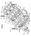
- an outer shell of a vehicle in-line 4-cylinder engine E comprises, sequentially from top to down, a head cover 11, a cylinder head 12, a cylinder block 13, a lower block 14 and an oil pan 15, which are coupled or laminated together.
- a secondary balancer device 16 is fixed to a lower surface of the lower block 14, and accommodated within the oil pan 15.
- the secondary balancer device 16 includes a drive balancer shaft 18 and a follower balancer shaft 19 (see Fg.4) which are supported in a balancer housing 17.
- a balancer drive chain 23 provides connection between a drive sprocket 21 and a follower sprocket 22.
- the drive sprocket 21 is mounted at an end of a crankshaft 20 supported between the cylinder block 13 and the lower block 14.
- the follower sprocket 22 is mounted at an end of the drive balancer shaft 18.
- the balancer housing 17 of the secondary balancer device 16 comprises: an upper housing member 29 and a lower housing member 30 which are coupled to each other by a plurality of bolts 31; and an end housing member 35 coupled to one end of the upper housing member 29 and one end of the lower housing member 30 by a plurality of bolts 36.
- the balancer housing 17 is fixed to the lower block 14 by tightening two bolts 37, 37 passed through the lower housing member 30 and the upper housing member 29 into the lower block 14, and tightening an additional two bolts 38, 38 passed through the end housing member 35 into the lower surface of the lower block 14.
- the follower sprocket 22 Provided on the drive balancer shaft 18 of the secondary balancer device 16, sequentially from one end to the other end thereof, are the follower sprocket 22, a first journal 18a, a drive gear 18b, a first balancer weight 18c, a second journal 18d, and a second balancer weight 18e.
- the first and second journals 18a and 18d are supported so as to be sandwiched between the upper housing member 29 and the lower housing member 30 (see Fig.5 ).
- a first journal 19a, a follower gear 19b, a first balancer weight 19c, a second journal 19d, and a second balancer weight 19e are supported so as to be sandwiched between the upper housing member 29 and the lower housing member 30 (see Fig.6 ).
- An oil pump 41 (see Fig. 6 ) is mounted at one end of the follower balancer shaft 19 extending toward the end housing member 35.
- the oil pump 41 comprises a well-known trochoid pump, including an inner rotor 42 fixed to the follower balancer shaft 19 and an outer rotor 43 rotatably supported on the end housing member 35 and meshed with the inner rotor 42.
- a strainer 44 is mounted on a lower surface of the lower housing member 30 to situate below a surface of oil stored in the oil pan 15. The strainer 44 is connected to a suction port 41a of the oil pump 41 through an oil passage 30a formed in the lower housing member 30.
- a discharge port 41b of the oil pump 41 communicates with a main gallery (not shown), and also communicates with a reservoir chamber 35b formed in an outer end face of the end housing member 35 through an oil passage 35a formed in the end housing member 35.
- the balancer drive chain 23 is wound around the drive sprocket 21 mounted on the crankshaft 20 and the follower sprocket 22 mounted on the drive balancer shaft 18.
- a tensioned side of the balancer drive chain 23 is guided by a chain guide 45.
- a loosened or relaxed side of the balancer drive chain 23 is pressed by a shoe 47 pivotally supported by a pivot shaft 46.
- a tensioner 49 is fixed to a surface of the end housing member 35 of the balancer housing 17 by bolts 48, 48. The shoe 47 is pushed against the balancer drive chain 23 by an output rod 50 of the tensioner 49.
- the tensioner 49 is fixed to a mounting seat 35c which is formed on the end housing member 35 so as to surround the reservoir chamber 35b.
- the output rod 50 is connected to a piston 52 slidably fitted in a cylinder 51 formed within the tensioner 49.
- An oil chamber 53 behind the piston 52 communicates with the reservoir chamber 35b through oil passage 35j.
- the reservoir chamber 35b communicates with a rear chamber 35e through a constriction 35d, and the rear chamber 35e communicates with a second communication chamber 35i formed in a parting face of the end housing member 35 through oil passage 35f formed through the end housing member 35, a first communication chamber 35g formed in the parting face of the end housing member 35, and an oil passage 35h formed through the end housing member 35.
- An oil jet member 55 is fixed by a bolt 56 to the parting face of the end housing member 35 via a knock pin 54.
- the oil jet member 55 has a bolt bore 55a having a diameter larger than an outer diameter of the bolt 56, and a first jet member nozzle 55b and a second jet member nozzle 55c which communicate with the bolt bore 55a.
- the crankshaft 20 and the drive balancer shaft 18 are rotated in a clockwise direction, whereby the first jet member nozzle 55b is directed to meshed portions of the drive sprocket 21 of the crankshaft 20 and the balancer drive chain 23, and the second jet member nozzle 55c is directed to meshed portions of the follower sprocket 22 of the drive balancer shaft 18 and the balancer drive chain 23.
- the rotational energy of the crankshaft 20 is transmitted to the drive balancer shaft 18 through the drive sprocket 21, the balancer drive chain 23 and the follower sprocket 22, and the rotational energy of the drive balancer shaft 18 is transmitted to the follower balancer shaft 19 through the drive gear 18b and the follower gear 19b.
- the number of teeth of the drive sprocket 21 of the crankshaft 20 is set to be twice the number of teeth of the follower sprocket 22 of the drive balancer shaft 18, and the number of teeth of the drive gear 18b is set to be equal to the number of teeth of the follower gear 19b.
- the drive balancer shaft 18 and the follower balancer shaft 19 are rotated in opposite directions at a rotational speed twice the rotational speed of the crankshaft 20, and a secondary vibration of the engine E is reduced by the first and second balancer weights 18c, 19c; 18e, 19e mounted on the drive balancer shaft 18 and the follower balancer shaft 19.
- the oil within the oil pan 15 flows from the strainer 44, through the oil passage 30a of the lower housing member 30 and the suction port 41a of the oil pump 41, to be discharged from the discharge port 41b.
- the discharged oil is used for lubrication and the like of various portions of the engine E, but a portion thereof is supplied to the oil chamber 53 in the tensioner 49 through the oil passage 35a, the reservoir chamber 35b and the oil passage 35j in the end housing member 35.
- the piston 52 is advanced relative to the cylinder 51 of the tensioner 49, and the output rod 50 integral with the piston 52 pushes the shoe 47 against the balancer driver chain 23, thereby maintaining the tension of the balancer driver chain 23 at an appropriate level.
- the reservoir chamber 35b is incorporated in a passage extending from the oil pump 41 to the tensioner 49, and hence a fluctuation in pressure discharged from the oil pump 41 can be absorbed in the reservoir chamber 35b, thereby stabilizing operation of the tensioner 49.
- a portion of the oil in the reservoir chamber 35b is passed through the constriction 35d, the rear chamber 35e, the oil passage 35f, the first communication chamber 35g, the oil passage 35h, the second communication chamber 35i and the bolt bore 55a, and injected from the first jet member nozzle 55b and the second jet member nozzle 55c.
- the oil injected from the first jet member nozzle 55b to the meshed portions of the drive sprocket 21 of the crankshaft 20 and the balancer drive chain 23 lubricates the entire engaged portions of the drive sprocket 21 and the balancer drive chain 23.
- the oil injected from the second jet member nozzle 55c to the meshed portions of the follower sprocket 22 of the drive balancer shaft 18 and the balancer drive chain 23 lubricates the entire engaged sections of the follower sprocket 22 and the balancer drive chain 23.
- the constriction 35d is provided between the reservoir chamber 35b and the oil jet member 55, the pressure of oil injected from the oil jet member 55 can be adjusted as desired by adjusting a cross-sectional area of the constriction 35d. Further, a predetermined pressure can be maintained in the reservoir chamber 35b by a resistance to the flow of oil passing through the oil jet member 55.
- the engine E has a compact structure, and also because the oil jet member 55 is provided in the balancer housing 17, the oil passage interconnecting the reservoir chamber 35b and the oil jet member 55 can be simplified.
- the secondary balancer device 16 has been described as an example, but the present invention is also applicable to a primary balancer device.
- the oil jet member of the present invention may be an oil jet member for lubricating any member other than the endless power transmitting member.
- a tensioner for applying tension to a balancer drive chain is mounted in a balancer housing which accommodates balancer shafts. Oil is supplied from a reservoir chamber to the tensioner. An oil jet member for lubricating the balancer drive chain is mounted at a position downstream in an oil flow direction from the reservoir chamber. Therefore, while enabling foreign matter contained in the oil to be discharged from the oil jet member without being accumulated within the tensioner, a predetermined pressure can be maintained in the reservoir chamber by a resistance to the flow of oil passing through the oil jet member. Also, a constriction is provided between the reservoir chamber and the oil jet member. Therefore, it is difficult for the oil to flow out of the reservoir chamber even after stoppage of an engine, thereby supplying the oil to the tensioner upon the next start of the engine without delay. Thus, it is possible to prevent the foreign matter from entering the tensioner for the balancer drive chain.
Landscapes
- Engineering & Computer Science (AREA)
- General Engineering & Computer Science (AREA)
- Mechanical Engineering (AREA)
- Lubrication Of Internal Combustion Engines (AREA)
- Devices For Conveying Motion By Means Of Endless Flexible Members (AREA)
Claims (1)
- Moteur (E) comprenant :un élément de transmission de puissance sans fin (23) pour transmettre une force d'entraînement entre un arbre d'entraînement (20) et un axe de basculeur (18) ;un dispositif de tension hydraulique (49) pour fournir la tension à l'élément de transmission de puissance sans fin (23) ;une pompe à huile (41) pour alimenter l'huile au dispositif de tension hydraulique (49) ; etun élément de jet d'huile (55) qui injecte l'huile dans une partie lubrifiée ;une chambre de réservoir (35b) pour stocker à l'intérieur de cette dernière l'huile alimentée par la pompe à huile (41) afin de l'alimenter au dispositif de tension hydraulique (49) ;dans lequel un agencement de chambre de réservoir (35b, 35e) comprend la chambre de réservoir (35b) et une chambre arrière (35e) communiquant avec la chambre de réservoir (35b) par le biais d'un étranglement (35d) et est raccordé avec :un premier passage d'huile (35a) par lequel l'huile provenant de la pompe à huile (41) est alimentée dans la chambre de réservoir (35b) ;un deuxième passage d'huile (35j) par lequel l'huile est alimentée de la chambre de réservoir (35b) au dispositif de tension hydraulique (49) ; etun troisième passage d'huile (35f) par lequel l'huile est alimentée de la chambre arrière (35e) audit élément de jet d'huile (55),dans lequel l'arbre d'entraînement est un vilebrequin (20), l'axe de basculeur est un arbre d' équilibrage du vilebrequin (18), et l'élément de transmission de puissance sans fin est une chaîne d'entraînement de balancier (23) ; etdans lequel le moteur (E) comprend en outre un boîtier de balancier (17) qui comprend la chambre de réservoir (35b) et qui loge l'arbre d'équilibrage du vilebrequin (18),caractérisé en ce que le boîtier de balancier (17) a un élément de boîtier d'extrémité (35) sur lequel un siège de montage (35c) est formé afin d'entourer la chambre de réservoir (35b), dans lequel le dispositif de tension (49) est fixé sur le siège de montage (35c).
Applications Claiming Priority (1)
| Application Number | Priority Date | Filing Date | Title |
|---|---|---|---|
| JP2007009418A JP4999470B2 (ja) | 2007-01-18 | 2007-01-18 | エンジン |
Publications (2)
| Publication Number | Publication Date |
|---|---|
| EP1950455A1 EP1950455A1 (fr) | 2008-07-30 |
| EP1950455B1 true EP1950455B1 (fr) | 2011-03-30 |
Family
ID=39092037
Family Applications (1)
| Application Number | Title | Priority Date | Filing Date |
|---|---|---|---|
| EP08000120A Not-in-force EP1950455B1 (fr) | 2007-01-18 | 2008-01-04 | Moteur |
Country Status (4)
| Country | Link |
|---|---|
| US (1) | US7882819B2 (fr) |
| EP (1) | EP1950455B1 (fr) |
| JP (1) | JP4999470B2 (fr) |
| DE (1) | DE602008005797D1 (fr) |
Families Citing this family (15)
| Publication number | Priority date | Publication date | Assignee | Title |
|---|---|---|---|---|
| CN109641514A (zh) * | 1968-11-29 | 2019-04-16 | 博格华纳瑞典公司 | 混合驱动模块 |
| US8181621B2 (en) * | 2009-07-17 | 2012-05-22 | Ford Global Technologies | Internal combustion engine with dynamic balancing system |
| JP5360120B2 (ja) * | 2010-06-21 | 2013-12-04 | マツダ株式会社 | エンジンのバランサ装置 |
| US9109690B2 (en) * | 2011-10-26 | 2015-08-18 | Ford Global Technologies, Llc | Pivot pin with internal oil passage |
| US8857400B2 (en) * | 2011-12-12 | 2014-10-14 | Honda Motor Co., Ltd. | Balancer device for an internal combustion engine |
| JP2014092206A (ja) * | 2012-11-01 | 2014-05-19 | Toyota Motor Corp | バランサ装置 |
| JP6204489B2 (ja) * | 2013-11-18 | 2017-09-27 | 川崎重工業株式会社 | エンジンの過給機 |
| JP6298350B2 (ja) * | 2014-04-26 | 2018-03-20 | ボーグワーナー インコーポレーテッド | オイルジェットアームおよび当該オイルジェットアームを用いたチェーンスパンの潤滑方法、ならびにチェーンテンショニング装置および当該チェーンテンショニング装置を用いたチェーンスパンの潤滑方法 |
| EP3344900A1 (fr) * | 2015-08-31 | 2018-07-11 | BorgWarner Sweden AB | Stratégie de commande |
| US9631715B1 (en) * | 2015-10-20 | 2017-04-25 | Ford Global Technologies, Llc | One-piece integrated chain snubber and oil diverter for a transaxle |
| JP6256505B2 (ja) | 2016-03-17 | 2018-01-10 | マツダ株式会社 | エンジンの補機駆動装置 |
| WO2018096842A1 (fr) * | 2016-11-25 | 2018-05-31 | マツダ株式会社 | Structure d'alimentation en huile pour système de chaîne de distribution |
| JP6264434B1 (ja) * | 2016-11-25 | 2018-01-24 | マツダ株式会社 | タイミングチェーンシステムのオイル供給構造 |
| JP6299849B1 (ja) * | 2016-11-25 | 2018-03-28 | マツダ株式会社 | タイミングチェーンシステムのオイル供給構造 |
| JP6615254B2 (ja) * | 2018-03-20 | 2019-12-04 | 本田技研工業株式会社 | 内燃機関 |
Family Cites Families (11)
| Publication number | Priority date | Publication date | Assignee | Title |
|---|---|---|---|---|
| GB562487A (en) * | 1942-04-27 | 1944-07-04 | Century Motors Corp | Improvements in or relating to the lubrication of internal combustion engines |
| JPH08210343A (ja) * | 1994-11-28 | 1996-08-20 | Nissan Motor Co Ltd | 内燃機関のコンロッド軸受構造 |
| JP3127354B2 (ja) * | 1996-02-06 | 2001-01-22 | 本田技研工業株式会社 | エンジンにおけるチェーンテンショナーの支持構造 |
| US5743230A (en) * | 1996-02-06 | 1998-04-28 | Honda Giken Kogyo Kabushiki Kaisha | Balancer shaft supporting structure in engine |
| JP3371727B2 (ja) * | 1996-12-20 | 2003-01-27 | スズキ株式会社 | チェーンアジャスタのオイル供給構造 |
| JP3712865B2 (ja) * | 1998-08-12 | 2005-11-02 | 本田技研工業株式会社 | 往復ピストンエンジンのつり合い装置 |
| JP4091691B2 (ja) | 1998-08-12 | 2008-05-28 | 本田技研工業株式会社 | 往復ピストンエンジンのつり合い装置 |
| JP2001073732A (ja) * | 1999-09-05 | 2001-03-21 | Honda Motor Co Ltd | 内燃機関の潤滑装置 |
| JP2004132192A (ja) * | 2002-10-08 | 2004-04-30 | Toyota Motor Corp | 内燃機関の潤滑構造 |
| JP2005016511A (ja) * | 2003-06-03 | 2005-01-20 | Yamaha Motor Co Ltd | エンジンのバランサ構造 |
| JP2005061274A (ja) * | 2003-08-08 | 2005-03-10 | Yamaha Motor Co Ltd | 車両用エンジン |
-
2007
- 2007-01-18 JP JP2007009418A patent/JP4999470B2/ja not_active Expired - Fee Related
-
2008
- 2008-01-04 EP EP08000120A patent/EP1950455B1/fr not_active Not-in-force
- 2008-01-04 DE DE602008005797T patent/DE602008005797D1/de active Active
- 2008-01-17 US US12/009,178 patent/US7882819B2/en not_active Expired - Fee Related
Also Published As
| Publication number | Publication date |
|---|---|
| US7882819B2 (en) | 2011-02-08 |
| EP1950455A1 (fr) | 2008-07-30 |
| DE602008005797D1 (de) | 2011-05-12 |
| JP4999470B2 (ja) | 2012-08-15 |
| JP2008175138A (ja) | 2008-07-31 |
| US20080173275A1 (en) | 2008-07-24 |
Similar Documents
| Publication | Publication Date | Title |
|---|---|---|
| EP1950455B1 (fr) | Moteur | |
| EP0789164B1 (fr) | Support d'un arbre balancier d'un moteur à combustion interne | |
| DE3807183C2 (fr) | ||
| EP0789165B1 (fr) | Structure de lubrification d'un arbre rotatif | |
| US9540973B2 (en) | Oil passage structure of dry sump engine and oil passage structure of V-shaped dry sump engine | |
| JP2001317320A (ja) | 内燃機関の潤滑装置 | |
| JP4080120B2 (ja) | 内燃機関の潤滑構造 | |
| JP5171343B2 (ja) | 車両のパワーユニット | |
| EP3081830A1 (fr) | Dispositif de lubrification pour moteur à combustion interne | |
| JP2012026569A (ja) | エンジンのバランサ装置 | |
| JP2921321B2 (ja) | 内燃機関のチェーン駆動装置 | |
| JP3777369B2 (ja) | エンジンの二次バランサ装置 | |
| JP4733671B2 (ja) | 往復ピストンエンジンのつり合い装置 | |
| JP2011127443A (ja) | 内燃機関の潤滑装置 | |
| JP3668548B2 (ja) | エンジンにおけるバランサーシャフトの支持構造 | |
| JP4628377B2 (ja) | 燃料噴射ポンプ潤滑構造 | |
| JP5998832B2 (ja) | 内燃機関 | |
| JP3127354B2 (ja) | エンジンにおけるチェーンテンショナーの支持構造 | |
| JP4091691B2 (ja) | 往復ピストンエンジンのつり合い装置 | |
| DE102019118209B4 (de) | Verbrennungsmotor mit Ölkühler | |
| JP5096550B2 (ja) | 往復ピストンエンジンのつり合い装置 | |
| JP3748007B2 (ja) | エンジンのオイルリリーフ構造 | |
| JP3074884B2 (ja) | エンジンの潤滑装置 | |
| JP3193207B2 (ja) | 内燃機関の潤滑油供給装置 | |
| JPH0533688Y2 (fr) |
Legal Events
| Date | Code | Title | Description |
|---|---|---|---|
| PUAI | Public reference made under article 153(3) epc to a published international application that has entered the european phase |
Free format text: ORIGINAL CODE: 0009012 |
|
| 17P | Request for examination filed |
Effective date: 20080104 |
|
| AK | Designated contracting states |
Kind code of ref document: A1 Designated state(s): AT BE BG CH CY CZ DE DK EE ES FI FR GB GR HR HU IE IS IT LI LT LU LV MC MT NL NO PL PT RO SE SI SK TR |
|
| AX | Request for extension of the european patent |
Extension state: AL BA MK RS |
|
| AKX | Designation fees paid |
Designated state(s): DE FR GB |
|
| GRAP | Despatch of communication of intention to grant a patent |
Free format text: ORIGINAL CODE: EPIDOSNIGR1 |
|
| GRAS | Grant fee paid |
Free format text: ORIGINAL CODE: EPIDOSNIGR3 |
|
| RIN1 | Information on inventor provided before grant (corrected) |
Inventor name: KOYAMA, YOSHIAKI |
|
| GRAA | (expected) grant |
Free format text: ORIGINAL CODE: 0009210 |
|
| RAP1 | Party data changed (applicant data changed or rights of an application transferred) |
Owner name: HONDA MOTOR CO., LTD. |
|
| AK | Designated contracting states |
Kind code of ref document: B1 Designated state(s): DE FR GB |
|
| REG | Reference to a national code |
Ref country code: GB Ref legal event code: FG4D |
|
| REF | Corresponds to: |
Ref document number: 602008005797 Country of ref document: DE Date of ref document: 20110512 Kind code of ref document: P |
|
| REG | Reference to a national code |
Ref country code: DE Ref legal event code: R096 Ref document number: 602008005797 Country of ref document: DE Effective date: 20110512 |
|
| PLBE | No opposition filed within time limit |
Free format text: ORIGINAL CODE: 0009261 |
|
| STAA | Information on the status of an ep patent application or granted ep patent |
Free format text: STATUS: NO OPPOSITION FILED WITHIN TIME LIMIT |
|
| 26N | No opposition filed |
Effective date: 20120102 |
|
| REG | Reference to a national code |
Ref country code: DE Ref legal event code: R097 Ref document number: 602008005797 Country of ref document: DE Effective date: 20120102 |
|
| GBPC | Gb: european patent ceased through non-payment of renewal fee |
Effective date: 20120104 |
|
| PG25 | Lapsed in a contracting state [announced via postgrant information from national office to epo] |
Ref country code: GB Free format text: LAPSE BECAUSE OF NON-PAYMENT OF DUE FEES Effective date: 20120104 |
|
| PGFP | Annual fee paid to national office [announced via postgrant information from national office to epo] |
Ref country code: FR Payment date: 20140108 Year of fee payment: 7 |
|
| PGFP | Annual fee paid to national office [announced via postgrant information from national office to epo] |
Ref country code: DE Payment date: 20141231 Year of fee payment: 8 |
|
| REG | Reference to a national code |
Ref country code: FR Ref legal event code: ST Effective date: 20150930 |
|
| PG25 | Lapsed in a contracting state [announced via postgrant information from national office to epo] |
Ref country code: FR Free format text: LAPSE BECAUSE OF NON-PAYMENT OF DUE FEES Effective date: 20150202 |
|
| REG | Reference to a national code |
Ref country code: DE Ref legal event code: R119 Ref document number: 602008005797 Country of ref document: DE |
|
| PG25 | Lapsed in a contracting state [announced via postgrant information from national office to epo] |
Ref country code: DE Free format text: LAPSE BECAUSE OF NON-PAYMENT OF DUE FEES Effective date: 20160802 |