EP1950471A1 - Mecanisme de verrouillage de passage de vitesse - Google Patents
Mecanisme de verrouillage de passage de vitesse Download PDFInfo
- Publication number
- EP1950471A1 EP1950471A1 EP07001888A EP07001888A EP1950471A1 EP 1950471 A1 EP1950471 A1 EP 1950471A1 EP 07001888 A EP07001888 A EP 07001888A EP 07001888 A EP07001888 A EP 07001888A EP 1950471 A1 EP1950471 A1 EP 1950471A1
- Authority
- EP
- European Patent Office
- Prior art keywords
- gearshift
- gearbox
- leading wire
- control panel
- gear
- Prior art date
- Legal status (The legal status is an assumption and is not a legal conclusion. Google has not performed a legal analysis and makes no representation as to the accuracy of the status listed.)
- Withdrawn
Links
- 231100000572 poisoning Toxicity 0.000 claims abstract description 3
- 230000000607 poisoning effect Effects 0.000 claims abstract description 3
- 230000007935 neutral effect Effects 0.000 description 3
- 230000033001 locomotion Effects 0.000 description 2
- 239000004576 sand Substances 0.000 description 2
- 230000006835 compression Effects 0.000 description 1
- 238000007906 compression Methods 0.000 description 1
- 239000000428 dust Substances 0.000 description 1
- 238000000034 method Methods 0.000 description 1
Images

Classifications
-
- F—MECHANICAL ENGINEERING; LIGHTING; HEATING; WEAPONS; BLASTING
- F16—ENGINEERING ELEMENTS AND UNITS; GENERAL MEASURES FOR PRODUCING AND MAINTAINING EFFECTIVE FUNCTIONING OF MACHINES OR INSTALLATIONS; THERMAL INSULATION IN GENERAL
- F16H—GEARING
- F16H61/00—Control functions within control units of change-speed- or reversing-gearings for conveying rotary motion ; Control of exclusively fluid gearing, friction gearing, gearings with endless flexible members or other particular types of gearing
- F16H61/22—Locking of the control input devices
-
- F—MECHANICAL ENGINEERING; LIGHTING; HEATING; WEAPONS; BLASTING
- F16—ENGINEERING ELEMENTS AND UNITS; GENERAL MEASURES FOR PRODUCING AND MAINTAINING EFFECTIVE FUNCTIONING OF MACHINES OR INSTALLATIONS; THERMAL INSULATION IN GENERAL
- F16H—GEARING
- F16H61/00—Control functions within control units of change-speed- or reversing-gearings for conveying rotary motion ; Control of exclusively fluid gearing, friction gearing, gearings with endless flexible members or other particular types of gearing
- F16H61/18—Preventing unintentional or unsafe shift, e.g. preventing manual shift from highest gear to reverse gear
-
- F—MECHANICAL ENGINEERING; LIGHTING; HEATING; WEAPONS; BLASTING
- F16—ENGINEERING ELEMENTS AND UNITS; GENERAL MEASURES FOR PRODUCING AND MAINTAINING EFFECTIVE FUNCTIONING OF MACHINES OR INSTALLATIONS; THERMAL INSULATION IN GENERAL
- F16H—GEARING
- F16H59/00—Control inputs to control units of change-speed- or reversing-gearings for conveying rotary motion
- F16H59/02—Selector apparatus
- F16H59/08—Range selector apparatus
Definitions
- the invention relates to a gearshift mechanism.
- this novel gearshift mechanism features gearshift lock protection and failure reduction.
- gear ranges which are the forward range and the reverse range. Moreover, they have the neutral range and the parking range.
- An over-sand vehicle has fewer gear ranges, namely, forward range, normal range and reverse range.
- the gearshift must be shifted to the forward range while the over-sand vehicle is running forward. Damage to the gearbox occurs when the gear is shifted from the forward range to the reverse range suddenly. This may happen either when the vehicle is moving on a bumpy road or when the driver is performing unconventional motions and thus accidentally touches the gearshift lever.
- this accidental gearshift occurs in a vehicle with a plurality of forward gear ranges such as high speed forward range, middle speed forward range and low speed forward range, the gear goes through rapidly shifts among forward ranges of different speeds. The unpredictable gear shifts also cause damage to the gearbox.
- An object of the present invention is to provide protection to the gearshift and eliminate gearbox damage by locking the gear in a particular range.
- the gearshift lock protection mechanism of the present invention comprises a gearbox, a gearshift module and a gearshift lock controller
- the gearshift module comprises a control panel and a gearshift leading wire set
- the control panel is combined with a gearbox shaft of the gearbox, shifting gears of the gearbox by using the gearshift leading wire set to control the control panel and the gearbox shaft
- a plurality of gear ranges positioning holes which are located on the surface of the control panel
- the gearshift lock controller comprises a control valve which is linked to a gearshift poisoning leading wire, a positioning terminal located at the end of the gearshift positioning leading wire which is in one of the gear ranges positioning holes determined by the control valve, such that it can lock the gear in a particular range and eliminate the gearbox damage.
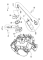
- a gearshift lock protection mechanism of the present invention comprises a gearbox 10, a gearshift module 30 and a gearshift lock controller 20;
- the gearshift module 30 comprises a control panel 32 and a gearshift leading wire set 31;
- the control panel 32 is combined with a gearbox shaft 11 of the gearbox 10;
- the driver controls the control panel 32 and the movement of the gearbox shaft 11 by gearshift leading wire set 31 which is controlled by the gearshift lever(not shown). In this way, the driver shifts the gear of the gearbox 10.
- gearshift lock controller 20 mainly comprises control valve 22 linked to gearshift positioning leading wire 21, whether the positioning terminal 212 connecting to the end of the gearshift positioning leading wire 21 is in one of the gear ranges positioning holes 321 is determined by the control valve 22.
- gearshift module 30 is covered by gearshift leading wire fixed cover 34 and gearshift leading wire fixed base 33, such that the gearshift module 30 is combined with the gearbox 30 by gearshift leading wire fixed base 33 for a more stable combination between the gearbox 10 and the gearshift module 30, and, the gearshift module 30 is combined with the gearshift lock controller 20 by gearshift leading wire fixed cover 34 for a more stable combination between the gearshift lock controller 20 and the gearshift module 30.
- gearshift leading wire fixed cover 34 and gearshift leading wire fixed base 33 also prevent the gearshift module 30 from dust.
- control valve 22 could be a electromagnetic valve, and an elastic element 211 is located between the gearshift positioning leading wire 21 and the positioning terminal 212.
- control valve 22 (which is electromagnetic valve) controls the compression and the expansion of elastic element 211 to determine whether control positioning terminal 212 is in one of the gear ranges positioning holes 32; wherein, the elastic element 211 is a spring. And, control valve 22 is fixed to the vehicle by control valve fixed panel 221.
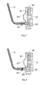
- Fig.3 Shown in Fig.3 is a representational side view of the gearshift lock protection mechanism in accordance with the preferred example of the present invention.
- the control valve 22 controls positioning terminal 212 in the gear ranges positioning holes 321 which are on the surface of the control panel 32, and it prevents the gears from being shifted through control panel 32 while the vehicle is running on high speed. Since the gearbox shaft 11 will not be moved, the gears will not experience accidental shifting. Therefore, damage to the gearbox can be eliminated.
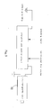
- Fig.4 and Fig.5 are the representational side view and the schematic representation of the gearshift lock protection mechanism in accordance with the preferred example of the present invention.
Landscapes
- Engineering & Computer Science (AREA)
- General Engineering & Computer Science (AREA)
- Mechanical Engineering (AREA)
- Gear-Shifting Mechanisms (AREA)
- Arrangement Or Mounting Of Control Devices For Change-Speed Gearing (AREA)
- Control Of Transmission Device (AREA)
Priority Applications (1)
| Application Number | Priority Date | Filing Date | Title |
|---|---|---|---|
| EP07001888A EP1950471A1 (fr) | 2007-01-29 | 2007-01-29 | Mecanisme de verrouillage de passage de vitesse |
Applications Claiming Priority (1)
| Application Number | Priority Date | Filing Date | Title |
|---|---|---|---|
| EP07001888A EP1950471A1 (fr) | 2007-01-29 | 2007-01-29 | Mecanisme de verrouillage de passage de vitesse |
Publications (1)
| Publication Number | Publication Date |
|---|---|
| EP1950471A1 true EP1950471A1 (fr) | 2008-07-30 |
Family
ID=38190763
Family Applications (1)
| Application Number | Title | Priority Date | Filing Date |
|---|---|---|---|
| EP07001888A Withdrawn EP1950471A1 (fr) | 2007-01-29 | 2007-01-29 | Mecanisme de verrouillage de passage de vitesse |
Country Status (1)
| Country | Link |
|---|---|
| EP (1) | EP1950471A1 (fr) |
Citations (1)
| Publication number | Priority date | Publication date | Assignee | Title |
|---|---|---|---|---|
| US5063817A (en) * | 1990-02-27 | 1991-11-12 | Bogert Donald L | Lockout system for automatic transmission |
-
2007
- 2007-01-29 EP EP07001888A patent/EP1950471A1/fr not_active Withdrawn
Patent Citations (1)
| Publication number | Priority date | Publication date | Assignee | Title |
|---|---|---|---|---|
| US5063817A (en) * | 1990-02-27 | 1991-11-12 | Bogert Donald L | Lockout system for automatic transmission |
Similar Documents
| Publication | Publication Date | Title |
|---|---|---|
| US6230579B1 (en) | Multi-mode shifter assembly joint | |
| US20190353241A1 (en) | Shift control apparatus for electronic shift system | |
| US7228753B2 (en) | Shift control apparatus for a transmission | |
| US20050056109A1 (en) | Shifting device for a shift-by-wire system | |
| US7971501B2 (en) | Shift lock assembly | |
| US20050223834A1 (en) | Inline automatic/manual shifter | |
| US20160327156A1 (en) | Electronic shift system for an automated manual transmission | |
| US4917224A (en) | Transmission and brake interlock system | |
| US20120298473A1 (en) | Emergency release mechanism for an automatic transmission | |
| US20030213673A1 (en) | Integrated position switch/brake transmission shift interlock component | |
| US6027426A (en) | Neutral sensing and shift lever interlock assembly for a vehicular transmission | |
| US7900532B2 (en) | Electric shifting device for a motor vehicle | |
| US20060248976A1 (en) | Shifting mechanism for an automated or automatic transmission | |
| US20080173118A1 (en) | Gearshift lock protection mechanism | |
| US8413534B2 (en) | Shifting device for a vehicle transmission | |
| EP1950471A1 (fr) | Mecanisme de verrouillage de passage de vitesse | |
| CN104565354B (zh) | 用于防止手动变速器的错误换档的装置 | |
| US8788158B2 (en) | Shifting device for vehicle and shifting system using the same | |
| US11598416B2 (en) | Interlocking device for a transmission | |
| KR20050098518A (ko) | 수동변속기의 변속조작기구 | |
| JP3475711B2 (ja) | 手動変速機の操作装置 | |
| US7476173B2 (en) | Park inhibit solenoid assembly and system incorporating the same | |
| EP2453149A1 (fr) | Inertie de levier dans une boîte de vitesses manuelle | |
| KR20260050726A (ko) | 전자식 변속조작장치 | |
| JPS60158521A (ja) | ロ−タリスイツチ装置 |
Legal Events
| Date | Code | Title | Description |
|---|---|---|---|
| PUAI | Public reference made under article 153(3) epc to a published international application that has entered the european phase |
Free format text: ORIGINAL CODE: 0009012 |
|
| AK | Designated contracting states |
Kind code of ref document: A1 Designated state(s): AT BE BG CH CY CZ DE DK EE ES FI FR GB GR HU IE IS IT LI LT LU LV MC NL PL PT RO SE SI SK TR |
|
| AX | Request for extension of the european patent |
Extension state: AL BA HR MK RS |
|
| 17P | Request for examination filed |
Effective date: 20081024 |
|
| AKX | Designation fees paid |
Designated state(s): AT BE BG CH CY CZ DE DK EE ES FI FR GB GR HU IE IS IT LI LT LU LV MC NL PL PT RO SE SI SK TR |
|
| 17Q | First examination report despatched |
Effective date: 20090402 |
|
| STAA | Information on the status of an ep patent application or granted ep patent |
Free format text: STATUS: THE APPLICATION IS DEEMED TO BE WITHDRAWN |
|
| 18D | Application deemed to be withdrawn |
Effective date: 20091013 |