EP1950479A2 - Rohrschelle - Google Patents
Rohrschelle Download PDFInfo
- Publication number
- EP1950479A2 EP1950479A2 EP08100532A EP08100532A EP1950479A2 EP 1950479 A2 EP1950479 A2 EP 1950479A2 EP 08100532 A EP08100532 A EP 08100532A EP 08100532 A EP08100532 A EP 08100532A EP 1950479 A2 EP1950479 A2 EP 1950479A2
- Authority
- EP
- European Patent Office
- Prior art keywords
- insert element
- clamp
- bracket
- sections
- curvature
- Prior art date
- Legal status (The legal status is an assumption and is not a legal conclusion. Google has not performed a legal analysis and makes no representation as to the accuracy of the status listed.)
- Granted
Links
Images

Classifications
-
- F—MECHANICAL ENGINEERING; LIGHTING; HEATING; WEAPONS; BLASTING
- F16—ENGINEERING ELEMENTS AND UNITS; GENERAL MEASURES FOR PRODUCING AND MAINTAINING EFFECTIVE FUNCTIONING OF MACHINES OR INSTALLATIONS; THERMAL INSULATION IN GENERAL
- F16L—PIPES; JOINTS OR FITTINGS FOR PIPES; SUPPORTS FOR PIPES, CABLES OR PROTECTIVE TUBING; MEANS FOR THERMAL INSULATION IN GENERAL
- F16L3/00—Supports for pipes, cables or protective tubing, e.g. hangers, holders, clamps, cleats, clips, brackets
- F16L3/08—Supports for pipes, cables or protective tubing, e.g. hangers, holders, clamps, cleats, clips, brackets substantially surrounding the pipe, cable or protective tubing
- F16L3/10—Supports for pipes, cables or protective tubing, e.g. hangers, holders, clamps, cleats, clips, brackets substantially surrounding the pipe, cable or protective tubing divided, i.e. with two members engaging the pipe, cable or protective tubing
-
- F—MECHANICAL ENGINEERING; LIGHTING; HEATING; WEAPONS; BLASTING
- F16—ENGINEERING ELEMENTS AND UNITS; GENERAL MEASURES FOR PRODUCING AND MAINTAINING EFFECTIVE FUNCTIONING OF MACHINES OR INSTALLATIONS; THERMAL INSULATION IN GENERAL
- F16L—PIPES; JOINTS OR FITTINGS FOR PIPES; SUPPORTS FOR PIPES, CABLES OR PROTECTIVE TUBING; MEANS FOR THERMAL INSULATION IN GENERAL
- F16L55/00—Devices or appurtenances for use in, or in connection with, pipes or pipe systems
- F16L55/02—Energy absorbers; Noise absorbers
- F16L55/033—Noise absorbers
- F16L55/035—Noise absorbers in the form of specially adapted hangers or supports
Definitions
- the invention relates to a pipe clamp with at least one bow having a bow and at least one insert element, wherein the at least one clamp bracket has at least one recess for fixing the insert element and two adjacently extending bracket sections, and wherein the insert element at least one of a contact surface projecting rear engagement portion has, which partially engages the adjacently arranged longitudinal edges of the bracket sections.
- Such a clamp serves the fixation and retention of lines, such.
- lines such as pipes, cables or the like, on a substrate or on a support by means of a fastener, such as a threaded rod.
- a fastener such as a threaded rod.
- To isolate the fixed line such.
- insert elements are provided from an elastic material on the clamp bracket, which are set against unwanted displacement on the clamp bracket.
- the insert element has laterally arranged, U-shaped holding portions, which laterally surround the clamp bracket.
- Such insert element is z. B. in the US 4,189,807 shown.
- a disadvantage of this type of insert element is the relatively large material consumption for the formation of the insert element.
- the clamp bracket has a recess for the determination of the insert element and two adjacently extending bracket sections.
- the insert element has a rear engagement portion projecting from a contact surface, which engages behind the adjacent longitudinal edges of the strap portions in regions. The same over its entire length formed insert element can be clipped into the recess or retracted into this.
- a disadvantage of the known solution is that the bracket sections of the clamp bracket are easily displaced relative to each other and thereby the pipe clamp is unstable. Especially with pipe clamps for cables with a large diameter, this behavior of the clamp bracket has a very disadvantageous.
- the object of the invention is to provide a pipe clamp with at least one clamp bracket and a liner, which is stable and easy to manufacture even for cables with large diameters.
- At least one reinforcing web which connects the two bow sections and protrudes outwards on the curvature side is provided, which forms a curvature-side inwardly open clearance open towards the at least one cutout.
- the reinforcing web stiffens the strap sections from each other and prevents a transverse displacement between them.
- the free space provided by the reinforcing web serves for the area-wise reception of the section of the rear gripping section of the insert element which projects beyond the clamp side on the outside of the clip in the region of the clamp strap adjacent to the at least one recess. Since the free space is open to the at least one recess, the rear engagement portion of the insert element can be easily retracted into the slot-shaped recess, which allows an arrangement of a larger undercut surface of the Schugreifabitess than a einclipsbaren insert element. In addition, only a smaller clearance between the rear engagement portion and the longitudinal edges of the bracket sections must be provided.
- the insert element has over its entire longitudinal extent advantageously the same configuration and is thus simple and inexpensive to produce. Furthermore, the material requirement for the production of the insert element is lower than in the case of an insert element which has holding sections which laterally embrace the clamp clip.
- the insert element is easy to assemble and disassemble.
- the pipe clamp can be used with or without the insert element, wherein the user can easily remove the insert element from the pipe clamp, if necessary.
- the user can easily and quickly set the specified on the clamp bracket insert element as needed replace another, according to the requirements insert element on the pipe clamp.
- the at least one reinforcing web has two ramp sections and a connecting section arranged at a distance from the clamp yoke.
- the ends of the reinforcing web for example, each form-fitting manner by means of welding or soldering with the yoke portions of the clamp bracket.
- the connecting portion is curved at least partially curvature side outwards, whereby an advantageous stiffening of the clamp bracket is ensured. Due to the resulting substantially U-shaped configuration, it is easy to form a sufficiently large clearance for the portion of the rear grip portion of the insert element that projects beyond the side of the clamp bow on the outside.
- the at least one reinforcing web is formed on the clamp bracket bead, which is easily and inexpensively formed on the clamp bracket.
- the clamp bracket is made of sheet metal in a stamping / bending process.
- the clamp bracket is punched out of a flat material, provided with a plurality of linearly arranged one behind the other and spaced from each other recesses. The remaining between the recesses sections are beaded and form the reinforcing webs of the clamp bracket.
- At least three reinforcing webs and two recesses arranged between them are provided on the at least one clamp bracket. If the clamp on the clamp bracket on the bend side or radially outwardly projecting flanges, so two reinforcing webs are advantageously provided in each case in the region of the bending point of the flanges whose curvilinear free space on the one hand to the recesses and on the other hand to the outside are open.
- the at least one further reinforcing web is arranged between the recesses, wherein the curvature-side inner free space is open to the adjacent recesses and connects them.
- connection head is arranged on the at least one reinforcing web.
- a corresponding section of the reinforcing web advantageously has a flat plateau section, on which, for example, a nut is arranged as a connection head for fixing the pipe clamp to a substrate by means of a fastening element.
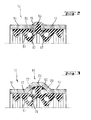
- the in the FIGS. 1 to 3 illustrated clamp 11 has two clamp brackets 12 and 32, on each of which an insert element 51 and 61 is arranged.
- the clamp brackets 12 and 32 each have a semicircular curved portion 13 and 33 as a curvature and at the free ends on the curvature side or radially outwardly projecting flanges 14 and 34, respectively.
- the two clamp brackets 12 and 32 are clamped together.
- each clamp bracket 12 and 32 two recesses 15 and 35 for the determination of the insert element 51 and 61 and adjacent thereto two mutually extending strap sections 16 and 36, respectively.
- Each insert member 51 and 61 has a projecting from a contact surface 52 rear engagement portion 53 which engages the adjacently arranged longitudinal edges 17 of the strap sections 16 and 36 in regions.
- each reinforcing web 18, 19, 38 and 39 has two ramp sections 22, 23, 42 and 43, which are connected to a corresponding connecting portion 20, 21, 40 and 41, respectively, and to the bow sections 16 and 36, respectively.
- the reinforcing webs 18, 19, 38 and 39 are formed on the clamp bracket beads and bent curvature side to the outside.
- a reinforcing web 19 and 39 formed on the clamp brackets 12 and 32.
- a plateau 24 for the arrangement of a nut is designed as a connection head 57 for the pipe clamp 11.
Landscapes
- Engineering & Computer Science (AREA)
- General Engineering & Computer Science (AREA)
- Mechanical Engineering (AREA)
- Supports For Pipes And Cables (AREA)
- Mutual Connection Of Rods And Tubes (AREA)
- Carriages For Children, Sleds, And Other Hand-Operated Vehicles (AREA)
- Clamps And Clips (AREA)
Abstract
Description
- Die Erfindung betrifft eine Rohrschelle mit zumindest einem eine Krümmung aufweisenden Schellenbügel und mit zumindest einem Einlageelement, wobei der zumindest eine Schellenbügel zumindest eine Ausnehmung für die Festlegung des Einlageelementes und zwei benachbart dazu verlaufende Bügelabschnitte aufweist, und wobei das Einlageelement zumindest einen von einer Anlagefläche abragenden Hintergreifabschnitt aufweist, der die benachbart zueinander angeordneten Längsränder der Bügelabschnitte bereichsweise hintergreift.
- Eine derartige Rohrschelle dient der Fixierung und Halterung von Leitungen, wie z. B. von Rohren, Kabeln oder dergleichen, an einem Untergrund oder an einem Träger mittels eines Befestigungselementes, wie beispielsweise einer Gewindestange. Zur Isolierung der fixierten Leitung, wie z. B. zur Schallisolierung von Rohrleitungen gegenüber Gebäudeteilen werden Einlageelemente aus einem elastischen Material an dem Schellenbügel vorgesehen, welche gegen unerwünschte Verschiebung am Schellenbügel festgelegt sind.
- Beispielsweise weist das Einlageelement dazu seitlich angeordnete, U-förmige Halteabschnitte auf, die den Schellenbügel seitlich umgreifen. Ein derartiges Einlageelement ist z. B. in der
US 4,189,807 gezeigt. Nachteilig an dieser Art von Einlageelement ist der verhältnismässig grosse Materialverbrauch zur Ausbildung des Einlageelementes. - Aus der
GB 718,527 - Nachteilig an der bekannten Lösung ist, dass die Bügelabschnitte des Schellenbügels leicht zueinander verschiebbar sind und dadurch die Rohrschelle instabil ist. Insbesondere bei Rohrschellen für Leitungen mit grossem Durchmesser wirkt sich dieses Verhalten des Schellenbügels sehr nachteilig aus.
- Aufgabe der Erfindung ist es, eine Rohrschelle mit zumindest einem Schellenbügel und einem Einlageelement zu schaffen, die auch für Leitungen mit grossen Durchmessern stabil sowie einfach und wirtschaftlich zu fertigen ist.
- Die Aufgabe ist durch die Merkmale des unabhängigen Anspruchs gelöst. Vorteilhafte Weiterbildungen sind in den Unteransprüchen dargelegt.
- Gemäss der Erfindung ist zumindest ein die beiden Bügelabschnitte verbindender, krümmungsseitig nach aussen abragender Verstärkungssteg vorgesehen, der einen krümmungsseitig innenliegenden, zu der zumindest einen Ausnehmung hin offenen Freiraum ausbildet.
- Der Verstärkungssteg steift die Bügelabschnitte zueinander aus und verhindert eine Querverschiebung zwischen diesen. Der von dem Verstärkungssteg geschaffene Freiraum dient der bereichsweisen Aufnahme des den Schellenbügel krümmungsseitig aussen überragenden Abschnitt des Hintergreifabschnitts des Einlageelementes in dem der zumindest einen Ausnehmung benachbarten Bereichs des Schellenbügels. Da der Freiraum zu der zumindest einen Ausnehmung hin offen ist, kann der Hintergreifabschnitt des Einlageelementes einfach in die schlitzförmige Ausnehmung eingezogen werden, was eine Anordnung einer grösseren Hinterschnittfläche des Hintergreifabschnitts als bei einem einclipsbaren Einlageelement ermöglicht. Zudem muss nur ein geringeres Spiel zwischen dem Hintergreifabschnitt und den Längsrändern der Bügelabschnitte vorgesehen werden. Dies zusammen führt zu grösseren Haltekräften des festgelegten Einlageprofils, als bei einer einclipsbaren Lösung möglich sind. Das Einlageelement weist auf seiner gesamten Längserstreckung vorteilhaft die gleiche Ausgestaltung auf und ist somit einfach und kostengünstig herstellbar. Des Weiteren ist der Materialbedarf zur Fertigung des Einlageelementes geringer als bei einem Einlageelement, das den Schellenbügel seitlich umgreifende Halteabschnitte aufweist.
- Das Einlageelement ist einfach montierbar und auch demontierbar. Die Rohrschelle kann mit oder ohne das Einlageelement verwendet werden, wobei der Anwender bei Bedarf das Einlageelement einfach aus der Rohrschelle entfernen kann. Zudem kann der Anwender je nach Bedarf das an dem Schellenbügel festgelegte Einlageelement einfach und schnell gegen ein anderes, den Erfordernissen entsprechendes Einlageelement an der Rohrschelle ersetzen.
- Vorteilhaft weist der zumindest eine Verstärkungssteg zwei Rampenabschnitte und einen beabstandet zu dem Schellenbügel angeordneten Verbindungsabschnitt auf. Die Enden des Verstärkungssteges sind beispielsweise jeweils mittels Schweissen oder Löten mit den Bügelabschnitten des Schellenbügels formschlüssig verbunden.
- Bevorzugt ist der Verbindungsabschnitt zumindest bereichsweise krümmungsseitig nach aussen gebogen, wodurch eine vorteilhafte Aussteifung des Schellenbügels gewährleistet wird. Durch die daraus resultierende im Wesentlichen U-förmige Ausgestaltung, lässt sich einfach ein ausreichend grosser Freiraum für den, den Schellenbügel krümmungsseitig aussen überragenden Abschnitt des Hintergreifabschnitts des Einlageelementes ausbilden.
- Vorzugsweise ist der zumindest eine Verstärkungssteg eine am Schellenbügel ausgebildete Sicke, welche einfach und kostengünstig an dem Schellenbügel ausformbar ist. Vorteilhaft ist der Schellenbügel aus Blech in einem Stanz-/Biegeverfahren gefertigt. Beispielsweise wird der Schellenbügel aus einem Flachmaterial ausgestanzt, mit mehreren linear hintereinander angeordneten sowie zueinander beabstandeten Ausnehmungen versehen. Die zwischen den Ausnehmungen verbleibenden Abschnitte werden gesickt und bilden die Verstärkungsstege des Schellenbügels aus.
- Bevorzugt sind zumindest drei Verstärkungsstege sowie zwei zwischen diesen angeordnete Ausnehmungen an dem zumindest einen Schellenbügel vorgesehen. Weist die Rohrschelle am Schellenbügel krümmungsseitig beziehungsweise radial nach aussen abragende Flansche auf, so sind zwei Verstärkungsstege vorteilhaft jeweils im Bereich der Abbiegestelle der Flansche vorgesehen, deren krümmungsseitig innenliegender Freiraum einerseits zu den Ausnehmungen und andererseits nach aussen hin offen sind. Der zumindest eine weitere Verstärkungssteg ist zwischen den Ausnehmungen angeordnet, wobei dessen krümmungsseitig innenliegender Freiraum zu den benachbarten Ausnehmungen offen ist und diese verbindet.
- Vorzugsweise ist ein Anschlusskopf an dem zumindest einen Verstärkungssteg angeordnet. Ein entsprechender Abschnitt des Verstärkungssteges weist vorteilhaft einen ebenen Plateauabschnitt auf, an dem beispielsweise eine Mutter als Anschlusskopf zur Festlegung der Rohrschelle an einem Untergrund mittels eines Befestigungselementes angeordnet ist.
- Die Erfindung wird nachstehend anhand eines Ausführungsbeispieles näher erläutert. Es zeigen:
- Fig. 1
- Eine erfindungsgemässe Rohrschelle in der Seitenansicht;
- Fig. 2
- einen Schnitt durch einen Schellenbügel entlang Linie II-II in
Fig. 1 ; und - Fig. 3
- einen Schnitt durch den Schellenbügel entlang Linie III-III in
Fig. 1 . - Grundsätzlich sind in den Figuren gleiche Teile mit den gleichen Bezugszeichen versehen.
- Die in den
Figuren 1 bis 3 dargestellte Rohrschelle 11 weist zwei Schellenbügel 12 und 32 auf, an denen jeweils ein Einlageelement 51 und 61 angeordnet ist. Die Schellenbügel 12 und 32 weisen jeweils einen halbkreisförmig gebogenen Abschnitt 13 bzw. 33 als Krümmung sowie an deren freien Enden krümmungsseitig beziehungsweise radial nach aussen abragende Flansche 14 bzw. 34 auf. Über in den Flanschen 14 und 34 angeordnete Spannschrauben 56 sind die beiden Schellenbügel 12 und 32 miteinander verspannbar. Weiter weist jeder Schellenbügel 12 und 32 zwei Ausnehmungen 15 bzw. 35 für die Festlegung des Einlageelementes 51 bzw. 61 und benachbart dazu zwei zueinander verlaufende Bügelabschnitte 16 bzw. 36 auf. - Jedes Einlageelement 51 und 61 weist einen von einer Anlagefläche 52 abragenden Hintergreifabschnitt 53 auf, der die benachbart zueinander angeordneten Längsränder 17 der Bügelabschnitte 16 bzw. 36 bereichsweise hintergreift.
- An jedem Schellenbügel 12 und 32 sind drei die beiden Bügelabschnitte 16 bzw. 36 verbindende, krümmungsseitig beziehungsweise radial nach aussen abragende Verstärkungsstege 18, 19 bzw. 38, 39 vorgesehen, die jeweils einen krümmungsseitig innenliegenden, zu den Ausnehmungen 15 bzw. 35 hin offenen Freiraum 25, 26 bzw. 45, 46 ausbilden. Jeder Verstärkungssteg 18, 19, 38 und 39 weist zwei Rampenabschnitte 22, 23, 42 und 43 auf, die mit einem entsprechenden Verbindungsabschnitt 20, 21, 40 bzw. 41 sowie mit den Bügelabschnitten 16 bzw. 36 verbunden sind. Die Verstärkungsstege 18, 19, 38 und 39 sind am Schellenbügel ausgebildete Sicken und krümmungsseitig nach aussen gebogen. Jeweils im Abbiegebereich zwischen den Flanschen 14 bzw. 34 sind zwei Verstärkungsstege 18 bzw. 38 und in der Mitte zwischen den Ausnehmungen 15 bzw. 35 ist jeweils ein Verstärkungssteg 19 bzw. 39 an den Schellenbügeln 12 und 32 ausgebildet. An dem Verbindungsabschnitt 21 des Verstärkungssteges 19 ist ein Plateau 24 für die Anordnung einer Mutter als Anschlusskopf 57 für die Rohrschelle 11 ausgebildet.
Claims (5)
- Rohrschelle mit zumindest einem eine Krümmung aufweisenden Schellenbügel (12, 32) und mit zumindest einem Einlageelement (51, 61), wobei
der zumindest eine Schellenbügel (12, 32) zumindest eine Ausnehmung (15, 35) für die Festlegung des Einlageelementes (51, 61) und zwei benachbart dazu verlaufende Bügelabschnitte (16, 36) aufweist, und wobei
das Einlageelement (51, 61) zumindest einen von einer Anlagefläche (52) abragenden Hintergreifabschnitt (53) aufweist, der die benachbart zueinander angeordneten Längsränder (17) der Bügelabschnitte (16, 36) bereichsweise hintergreift, dadurch gekennzeichnet, dass
zumindest ein die beiden Bügelabschnitte (16, 36) verbindender, krümmungsseitig nach aussen abragender Verstärkungssteg (18, 19, 38, 39) vorgesehen ist, der einen krümmungsseitig innenliegenden, zu der zumindest einen Ausnehmung (15, 35) hin offenen Freiraum (25) ausbildet. - Rohrschelle nach Anspruch 1, dadurch gekennzeichnet, dass der Verstärkungssteg (18, 19, 38, 39) zumindest bereichsweise krümmungsseitig nach aussen gebogen ist.
- Rohrschelle nach Anspruch 1 oder 2, dadurch gekennzeichnet, dass der zumindest eine Verstärkungssteg (18, 19, 38, 39) eine am Schellenbügel (12, 32) ausgebildete Sicke ist.
- Rohrschelle nach einem der Ansprüche 1 bis 3, dadurch gekennzeichnet, dass zumindest drei Verstärkungsstege (18, 19, 38, 39) und zumindest zwei zwischen diesen angeordnete Ausnehmungen (15, 35) an dem zumindest einen Schellenbügel (12, 32) vorgesehen sind.
- Rohrschelle nach einem der Ansprüche 1 bis 4, dadurch gekennzeichnet, dass ein Anschlusskopf (57) an dem zumindest einen Verstärkungssteg (19) angeordnet ist.
Applications Claiming Priority (1)
| Application Number | Priority Date | Filing Date | Title |
|---|---|---|---|
| DE102007000035A DE102007000035A1 (de) | 2007-01-25 | 2007-01-25 | Rohrschelle |
Publications (3)
| Publication Number | Publication Date |
|---|---|
| EP1950479A2 true EP1950479A2 (de) | 2008-07-30 |
| EP1950479A3 EP1950479A3 (de) | 2008-12-03 |
| EP1950479B1 EP1950479B1 (de) | 2010-08-11 |
Family
ID=39521992
Family Applications (1)
| Application Number | Title | Priority Date | Filing Date |
|---|---|---|---|
| EP08100532A Active EP1950479B1 (de) | 2007-01-25 | 2008-01-16 | Rohrschelle |
Country Status (4)
| Country | Link |
|---|---|
| EP (1) | EP1950479B1 (de) |
| AT (1) | ATE477444T1 (de) |
| DE (2) | DE102007000035A1 (de) |
| ES (1) | ES2349579T3 (de) |
Cited By (4)
| Publication number | Priority date | Publication date | Assignee | Title |
|---|---|---|---|---|
| DE102008036386A1 (de) * | 2008-08-05 | 2010-02-18 | Sina-Befestigungssysteme Gmbh | Rohrschelle und Profilelement für eine Rohrschelle |
| DE202012103440U1 (de) | 2012-09-10 | 2012-09-28 | Edgar Emil Sinn | Rohrschelle und Einlage für eine Rohrschelle |
| CN104832509A (zh) * | 2014-02-01 | 2015-08-12 | 通用汽车环球科技运作有限责任公司 | 用于至少一个纵长延伸的构件的保持卡圈 |
| CN110617378A (zh) * | 2019-08-09 | 2019-12-27 | 招商局邮轮制造有限公司 | 一种复合减振式管吊架 |
Families Citing this family (2)
| Publication number | Priority date | Publication date | Assignee | Title |
|---|---|---|---|---|
| DK177872B1 (da) * | 2013-07-01 | 2014-10-20 | Ngi As | Beslag og anvendelse |
| US10393290B2 (en) | 2017-05-22 | 2019-08-27 | Erico International Corporation | Clamp for circular objects |
Citations (5)
| Publication number | Priority date | Publication date | Assignee | Title |
|---|---|---|---|---|
| GB718527A (en) | 1951-12-14 | 1954-11-17 | Wright Howard Clayton | Improvements in clips, clamps or encircling members |
| CH562980A5 (en) | 1973-03-27 | 1975-06-13 | Gebert & Cie | Pipe clip with removable sector-type strips - these fit into semicircular halves secured between coupling flanges |
| US4189807A (en) | 1976-11-15 | 1980-02-26 | Viking Industries, Inc. | Clamp |
| DE8223337U1 (de) | 1982-08-19 | 1982-11-18 | Sikla GmbH & Co KG, 7201 Hausen | Rohrschelle |
| DE4205402C1 (en) | 1992-02-20 | 1993-07-15 | Combe Gmbh & Co. Rohrbau, 1000 Berlin, De | Pipe clamp acoustic,temp.and/or electric insulation - uses blocks of elastic material, with anchor-shaped holders,whose heads have locking nipples |
Family Cites Families (2)
| Publication number | Priority date | Publication date | Assignee | Title |
|---|---|---|---|---|
| DE1650019A1 (de) * | 1967-10-25 | 1972-03-02 | Getefo Ges Fuer Tech Fortschri | Geraeuschisolierte Rohrschelle |
| ES2154492T3 (es) * | 1997-06-14 | 2001-04-01 | Hilti Ag | Pieza suplementaria para una abrazadera para tubos. |
-
2007
- 2007-01-25 DE DE102007000035A patent/DE102007000035A1/de not_active Withdrawn
-
2008
- 2008-01-16 EP EP08100532A patent/EP1950479B1/de active Active
- 2008-01-16 ES ES08100532T patent/ES2349579T3/es active Active
- 2008-01-16 DE DE502008001097T patent/DE502008001097D1/de active Active
- 2008-01-16 AT AT08100532T patent/ATE477444T1/de active
Patent Citations (5)
| Publication number | Priority date | Publication date | Assignee | Title |
|---|---|---|---|---|
| GB718527A (en) | 1951-12-14 | 1954-11-17 | Wright Howard Clayton | Improvements in clips, clamps or encircling members |
| CH562980A5 (en) | 1973-03-27 | 1975-06-13 | Gebert & Cie | Pipe clip with removable sector-type strips - these fit into semicircular halves secured between coupling flanges |
| US4189807A (en) | 1976-11-15 | 1980-02-26 | Viking Industries, Inc. | Clamp |
| DE8223337U1 (de) | 1982-08-19 | 1982-11-18 | Sikla GmbH & Co KG, 7201 Hausen | Rohrschelle |
| DE4205402C1 (en) | 1992-02-20 | 1993-07-15 | Combe Gmbh & Co. Rohrbau, 1000 Berlin, De | Pipe clamp acoustic,temp.and/or electric insulation - uses blocks of elastic material, with anchor-shaped holders,whose heads have locking nipples |
Cited By (6)
| Publication number | Priority date | Publication date | Assignee | Title |
|---|---|---|---|---|
| DE102008036386A1 (de) * | 2008-08-05 | 2010-02-18 | Sina-Befestigungssysteme Gmbh | Rohrschelle und Profilelement für eine Rohrschelle |
| DE102008036386B4 (de) * | 2008-08-05 | 2012-03-15 | Sina Befestigungssysteme Gmbh | Rohrschelle und Profilelement für eine Rohrschelle |
| DE202012103440U1 (de) | 2012-09-10 | 2012-09-28 | Edgar Emil Sinn | Rohrschelle und Einlage für eine Rohrschelle |
| CN104832509A (zh) * | 2014-02-01 | 2015-08-12 | 通用汽车环球科技运作有限责任公司 | 用于至少一个纵长延伸的构件的保持卡圈 |
| GB2524375A (en) * | 2014-02-01 | 2015-09-23 | Gm Global Tech Operations Inc | Retaining clip for at least one elongate element |
| CN110617378A (zh) * | 2019-08-09 | 2019-12-27 | 招商局邮轮制造有限公司 | 一种复合减振式管吊架 |
Also Published As
| Publication number | Publication date |
|---|---|
| ES2349579T3 (es) | 2011-01-05 |
| DE502008001097D1 (de) | 2010-09-23 |
| EP1950479B1 (de) | 2010-08-11 |
| EP1950479A3 (de) | 2008-12-03 |
| DE102007000035A1 (de) | 2008-09-04 |
| ATE477444T1 (de) | 2010-08-15 |
Similar Documents
| Publication | Publication Date | Title |
|---|---|---|
| EP1852643B1 (de) | Schelle zum Befestigen eines rohr- oder schlauchförmigen Gegenstandes | |
| DE102007061288B4 (de) | Vorrichtung zum Verbinden von zwei Leitungen | |
| EP1950479B1 (de) | Rohrschelle | |
| EP1997976B1 (de) | Profilschiene | |
| EP3423745B1 (de) | Profilschelle | |
| DE202007019445U1 (de) | Schlauchklemme | |
| EP1888960B1 (de) | Verankerungselement für rohrkupplungen | |
| EP2251553A1 (de) | Verbindungselement für Rohre, Verfahren zum Verbinden von Rohren und Verwendung des Verbindungselementes | |
| EP2072874A1 (de) | Rohrschelle | |
| EP1767793A2 (de) | Befestigungsvorrichtung für die Befestigung von Solarpaneelen an einer Montageschiene | |
| EP1950480A1 (de) | Rohrschelle | |
| EP0769647A1 (de) | Spannschelle zum Befestigen einer Fluidleitung | |
| WO2010089065A1 (de) | Klemmeinrichtung | |
| DE102009045484A1 (de) | Leitungsabhängeeinrichtung | |
| EP2034227A2 (de) | Rohrschelle | |
| EP2918888B1 (de) | Schellenanordnung zur befestigung eines schlauches auf einem rohr oder stutzen | |
| DE102008036386A1 (de) | Rohrschelle und Profilelement für eine Rohrschelle | |
| EP2037164A2 (de) | Rohrschelle | |
| DE102008046181A1 (de) | Antennenhalter für eine Satellitenschüssel | |
| EP1979664B1 (de) | Spannschelle für hochdruck-schläuche | |
| DE102008019424B4 (de) | Rohrschelle | |
| DE29911199U1 (de) | Rohrschelle | |
| DE29920248U1 (de) | Rohrhalterung für einen Dachrinnenentwässerungsrohrstrang | |
| DE20317300U1 (de) | Klapprohrschelle | |
| EP2123843B1 (de) | Klemmelement |
Legal Events
| Date | Code | Title | Description |
|---|---|---|---|
| PUAI | Public reference made under article 153(3) epc to a published international application that has entered the european phase |
Free format text: ORIGINAL CODE: 0009012 |
|
| AK | Designated contracting states |
Kind code of ref document: A2 Designated state(s): AT BE BG CH CY CZ DE DK EE ES FI FR GB GR HR HU IE IS IT LI LT LU LV MC MT NL NO PL PT RO SE SI SK TR |
|
| AX | Request for extension of the european patent |
Extension state: AL BA MK RS |
|
| PUAL | Search report despatched |
Free format text: ORIGINAL CODE: 0009013 |
|
| AK | Designated contracting states |
Kind code of ref document: A3 Designated state(s): AT BE BG CH CY CZ DE DK EE ES FI FR GB GR HR HU IE IS IT LI LT LU LV MC MT NL NO PL PT RO SE SI SK TR |
|
| AX | Request for extension of the european patent |
Extension state: AL BA MK RS |
|
| 17P | Request for examination filed |
Effective date: 20090603 |
|
| 17Q | First examination report despatched |
Effective date: 20090715 |
|
| AKX | Designation fees paid |
Designated state(s): AT BE BG CH CY CZ DE DK EE ES FI FR GB GR HR HU IE IS IT LI LT LU LV MC MT NL NO PL PT RO SE SI SK TR |
|
| GRAP | Despatch of communication of intention to grant a patent |
Free format text: ORIGINAL CODE: EPIDOSNIGR1 |
|
| GRAS | Grant fee paid |
Free format text: ORIGINAL CODE: EPIDOSNIGR3 |
|
| GRAA | (expected) grant |
Free format text: ORIGINAL CODE: 0009210 |
|
| AK | Designated contracting states |
Kind code of ref document: B1 Designated state(s): AT BE BG CH CY CZ DE DK EE ES FI FR GB GR HR HU IE IS IT LI LT LU LV MC MT NL NO PL PT RO SE SI SK TR |
|
| REG | Reference to a national code |
Ref country code: GB Ref legal event code: FG4D Free format text: NOT ENGLISH |
|
| REG | Reference to a national code |
Ref country code: CH Ref legal event code: EP |
|
| REG | Reference to a national code |
Ref country code: IE Ref legal event code: FG4D Free format text: LANGUAGE OF EP DOCUMENT: GERMAN |
|
| REF | Corresponds to: |
Ref document number: 502008001097 Country of ref document: DE Date of ref document: 20100923 Kind code of ref document: P |
|
| REG | Reference to a national code |
Ref country code: NL Ref legal event code: VDEP Effective date: 20100811 |
|
| REG | Reference to a national code |
Ref country code: ES Ref legal event code: FG2A Effective date: 20101222 |
|
| LTIE | Lt: invalidation of european patent or patent extension |
Effective date: 20100811 |
|
| PG25 | Lapsed in a contracting state [announced via postgrant information from national office to epo] |
Ref country code: LT Free format text: LAPSE BECAUSE OF FAILURE TO SUBMIT A TRANSLATION OF THE DESCRIPTION OR TO PAY THE FEE WITHIN THE PRESCRIBED TIME-LIMIT Effective date: 20100811 Ref country code: NL Free format text: LAPSE BECAUSE OF FAILURE TO SUBMIT A TRANSLATION OF THE DESCRIPTION OR TO PAY THE FEE WITHIN THE PRESCRIBED TIME-LIMIT Effective date: 20100811 Ref country code: NO Free format text: LAPSE BECAUSE OF FAILURE TO SUBMIT A TRANSLATION OF THE DESCRIPTION OR TO PAY THE FEE WITHIN THE PRESCRIBED TIME-LIMIT Effective date: 20101111 Ref country code: FI Free format text: LAPSE BECAUSE OF FAILURE TO SUBMIT A TRANSLATION OF THE DESCRIPTION OR TO PAY THE FEE WITHIN THE PRESCRIBED TIME-LIMIT Effective date: 20100811 |
|
| PGFP | Annual fee paid to national office [announced via postgrant information from national office to epo] |
Ref country code: MC Payment date: 20101230 Year of fee payment: 4 |
|
| PG25 | Lapsed in a contracting state [announced via postgrant information from national office to epo] |
Ref country code: CY Free format text: LAPSE BECAUSE OF FAILURE TO SUBMIT A TRANSLATION OF THE DESCRIPTION OR TO PAY THE FEE WITHIN THE PRESCRIBED TIME-LIMIT Effective date: 20100811 Ref country code: SI Free format text: LAPSE BECAUSE OF FAILURE TO SUBMIT A TRANSLATION OF THE DESCRIPTION OR TO PAY THE FEE WITHIN THE PRESCRIBED TIME-LIMIT Effective date: 20100811 Ref country code: PL Free format text: LAPSE BECAUSE OF FAILURE TO SUBMIT A TRANSLATION OF THE DESCRIPTION OR TO PAY THE FEE WITHIN THE PRESCRIBED TIME-LIMIT Effective date: 20100811 Ref country code: IS Free format text: LAPSE BECAUSE OF FAILURE TO SUBMIT A TRANSLATION OF THE DESCRIPTION OR TO PAY THE FEE WITHIN THE PRESCRIBED TIME-LIMIT Effective date: 20101211 Ref country code: BG Free format text: LAPSE BECAUSE OF FAILURE TO SUBMIT A TRANSLATION OF THE DESCRIPTION OR TO PAY THE FEE WITHIN THE PRESCRIBED TIME-LIMIT Effective date: 20101111 Ref country code: HR Free format text: LAPSE BECAUSE OF FAILURE TO SUBMIT A TRANSLATION OF THE DESCRIPTION OR TO PAY THE FEE WITHIN THE PRESCRIBED TIME-LIMIT Effective date: 20100811 |
|
| REG | Reference to a national code |
Ref country code: IE Ref legal event code: FD4D |
|
| PG25 | Lapsed in a contracting state [announced via postgrant information from national office to epo] |
Ref country code: GR Free format text: LAPSE BECAUSE OF FAILURE TO SUBMIT A TRANSLATION OF THE DESCRIPTION OR TO PAY THE FEE WITHIN THE PRESCRIBED TIME-LIMIT Effective date: 20101112 Ref country code: LV Free format text: LAPSE BECAUSE OF FAILURE TO SUBMIT A TRANSLATION OF THE DESCRIPTION OR TO PAY THE FEE WITHIN THE PRESCRIBED TIME-LIMIT Effective date: 20100811 Ref country code: SE Free format text: LAPSE BECAUSE OF FAILURE TO SUBMIT A TRANSLATION OF THE DESCRIPTION OR TO PAY THE FEE WITHIN THE PRESCRIBED TIME-LIMIT Effective date: 20100811 |
|
| PG25 | Lapsed in a contracting state [announced via postgrant information from national office to epo] |
Ref country code: DK Free format text: LAPSE BECAUSE OF FAILURE TO SUBMIT A TRANSLATION OF THE DESCRIPTION OR TO PAY THE FEE WITHIN THE PRESCRIBED TIME-LIMIT Effective date: 20100811 Ref country code: IE Free format text: LAPSE BECAUSE OF FAILURE TO SUBMIT A TRANSLATION OF THE DESCRIPTION OR TO PAY THE FEE WITHIN THE PRESCRIBED TIME-LIMIT Effective date: 20100811 |
|
| PGFP | Annual fee paid to national office [announced via postgrant information from national office to epo] |
Ref country code: IE Payment date: 20110112 Year of fee payment: 4 |
|
| PG25 | Lapsed in a contracting state [announced via postgrant information from national office to epo] |
Ref country code: RO Free format text: LAPSE BECAUSE OF FAILURE TO SUBMIT A TRANSLATION OF THE DESCRIPTION OR TO PAY THE FEE WITHIN THE PRESCRIBED TIME-LIMIT Effective date: 20100811 Ref country code: CZ Free format text: LAPSE BECAUSE OF FAILURE TO SUBMIT A TRANSLATION OF THE DESCRIPTION OR TO PAY THE FEE WITHIN THE PRESCRIBED TIME-LIMIT Effective date: 20100811 Ref country code: EE Free format text: LAPSE BECAUSE OF FAILURE TO SUBMIT A TRANSLATION OF THE DESCRIPTION OR TO PAY THE FEE WITHIN THE PRESCRIBED TIME-LIMIT Effective date: 20100811 Ref country code: SK Free format text: LAPSE BECAUSE OF FAILURE TO SUBMIT A TRANSLATION OF THE DESCRIPTION OR TO PAY THE FEE WITHIN THE PRESCRIBED TIME-LIMIT Effective date: 20100811 |
|
| PGFP | Annual fee paid to national office [announced via postgrant information from national office to epo] |
Ref country code: NL Payment date: 20110117 Year of fee payment: 4 Ref country code: FR Payment date: 20110128 Year of fee payment: 4 Ref country code: LU Payment date: 20110215 Year of fee payment: 4 |
|
| PLBE | No opposition filed within time limit |
Free format text: ORIGINAL CODE: 0009261 |
|
| STAA | Information on the status of an ep patent application or granted ep patent |
Free format text: STATUS: NO OPPOSITION FILED WITHIN TIME LIMIT |
|
| 26N | No opposition filed |
Effective date: 20110512 |
|
| PGFP | Annual fee paid to national office [announced via postgrant information from national office to epo] |
Ref country code: BE Payment date: 20110225 Year of fee payment: 4 |
|
| REG | Reference to a national code |
Ref country code: DE Ref legal event code: R097 Ref document number: 502008001097 Country of ref document: DE Effective date: 20110512 |
|
| PG25 | Lapsed in a contracting state [announced via postgrant information from national office to epo] |
Ref country code: MT Free format text: LAPSE BECAUSE OF FAILURE TO SUBMIT A TRANSLATION OF THE DESCRIPTION OR TO PAY THE FEE WITHIN THE PRESCRIBED TIME-LIMIT Effective date: 20100811 |
|
| BERE | Be: lapsed |
Owner name: HILTI AKTIENGESELLSCHAFT Effective date: 20120131 |
|
| PG25 | Lapsed in a contracting state [announced via postgrant information from national office to epo] |
Ref country code: MC Free format text: LAPSE BECAUSE OF NON-PAYMENT OF DUE FEES Effective date: 20120131 |
|
| GBPC | Gb: european patent ceased through non-payment of renewal fee |
Effective date: 20120116 |
|
| REG | Reference to a national code |
Ref country code: FR Ref legal event code: ST Effective date: 20120928 |
|
| PG25 | Lapsed in a contracting state [announced via postgrant information from national office to epo] |
Ref country code: GB Free format text: LAPSE BECAUSE OF NON-PAYMENT OF DUE FEES Effective date: 20120116 |
|
| PG25 | Lapsed in a contracting state [announced via postgrant information from national office to epo] |
Ref country code: FR Free format text: LAPSE BECAUSE OF NON-PAYMENT OF DUE FEES Effective date: 20120131 Ref country code: BE Free format text: LAPSE BECAUSE OF NON-PAYMENT OF DUE FEES Effective date: 20120131 |
|
| PG25 | Lapsed in a contracting state [announced via postgrant information from national office to epo] |
Ref country code: PT Free format text: LAPSE BECAUSE OF NON-PAYMENT OF DUE FEES Effective date: 20100811 |
|
| PG25 | Lapsed in a contracting state [announced via postgrant information from national office to epo] |
Ref country code: HU Free format text: LAPSE BECAUSE OF FAILURE TO SUBMIT A TRANSLATION OF THE DESCRIPTION OR TO PAY THE FEE WITHIN THE PRESCRIBED TIME-LIMIT Effective date: 20100811 |
|
| PG25 | Lapsed in a contracting state [announced via postgrant information from national office to epo] |
Ref country code: LU Free format text: LAPSE BECAUSE OF NON-PAYMENT OF DUE FEES Effective date: 20120116 |
|
| PG25 | Lapsed in a contracting state [announced via postgrant information from national office to epo] |
Ref country code: IE Free format text: LAPSE BECAUSE OF FAILURE TO SUBMIT A TRANSLATION OF THE DESCRIPTION OR TO PAY THE FEE WITHIN THE PRESCRIBED TIME-LIMIT Effective date: 20110224 |
|
| PGFP | Annual fee paid to national office [announced via postgrant information from national office to epo] |
Ref country code: ES Payment date: 20240223 Year of fee payment: 17 |
|
| PGFP | Annual fee paid to national office [announced via postgrant information from national office to epo] |
Ref country code: AT Payment date: 20240122 Year of fee payment: 17 |
|
| PGFP | Annual fee paid to national office [announced via postgrant information from national office to epo] |
Ref country code: DE Payment date: 20240119 Year of fee payment: 17 Ref country code: CH Payment date: 20240201 Year of fee payment: 17 |
|
| PGFP | Annual fee paid to national office [announced via postgrant information from national office to epo] |
Ref country code: TR Payment date: 20240115 Year of fee payment: 17 Ref country code: IT Payment date: 20240129 Year of fee payment: 17 |
|
| REG | Reference to a national code |
Ref country code: DE Ref legal event code: R119 Ref document number: 502008001097 Country of ref document: DE |
|
| REG | Reference to a national code |
Ref country code: CH Ref legal event code: PL |
|
| REG | Reference to a national code |
Ref country code: AT Ref legal event code: MM01 Ref document number: 477444 Country of ref document: AT Kind code of ref document: T Effective date: 20250116 |
|
| PG25 | Lapsed in a contracting state [announced via postgrant information from national office to epo] |
Ref country code: DE Free format text: LAPSE BECAUSE OF NON-PAYMENT OF DUE FEES Effective date: 20250801 |
|
| PG25 | Lapsed in a contracting state [announced via postgrant information from national office to epo] |
Ref country code: AT Free format text: LAPSE BECAUSE OF NON-PAYMENT OF DUE FEES Effective date: 20250116 |
|
| PG25 | Lapsed in a contracting state [announced via postgrant information from national office to epo] |
Ref country code: CH Free format text: LAPSE BECAUSE OF NON-PAYMENT OF DUE FEES Effective date: 20250131 |
|
| PG25 | Lapsed in a contracting state [announced via postgrant information from national office to epo] |
Ref country code: IT Free format text: LAPSE BECAUSE OF NON-PAYMENT OF DUE FEES Effective date: 20250116 |
|
| REG | Reference to a national code |
Ref country code: ES Ref legal event code: FD2A Effective date: 20260227 |
|
| PG25 | Lapsed in a contracting state [announced via postgrant information from national office to epo] |
Ref country code: ES Free format text: LAPSE BECAUSE OF NON-PAYMENT OF DUE FEES Effective date: 20250117 |