EP1950480B1 - Collier de serrage pour tuyaux - Google Patents
Collier de serrage pour tuyaux Download PDFInfo
- Publication number
- EP1950480B1 EP1950480B1 EP20080100533 EP08100533A EP1950480B1 EP 1950480 B1 EP1950480 B1 EP 1950480B1 EP 20080100533 EP20080100533 EP 20080100533 EP 08100533 A EP08100533 A EP 08100533A EP 1950480 B1 EP1950480 B1 EP 1950480B1
- Authority
- EP
- European Patent Office
- Prior art keywords
- opening
- flange
- clamp
- fact
- take
- Prior art date
- Legal status (The legal status is an assumption and is not a legal conclusion. Google has not performed a legal analysis and makes no representation as to the accuracy of the status listed.)
- Active
Links
Images

Classifications
-
- F—MECHANICAL ENGINEERING; LIGHTING; HEATING; WEAPONS; BLASTING
- F16—ENGINEERING ELEMENTS AND UNITS; GENERAL MEASURES FOR PRODUCING AND MAINTAINING EFFECTIVE FUNCTIONING OF MACHINES OR INSTALLATIONS; THERMAL INSULATION IN GENERAL
- F16L—PIPES; JOINTS OR FITTINGS FOR PIPES; SUPPORTS FOR PIPES, CABLES OR PROTECTIVE TUBING; MEANS FOR THERMAL INSULATION IN GENERAL
- F16L3/00—Supports for pipes, cables or protective tubing, e.g. hangers, holders, clamps, cleats, clips, brackets
- F16L3/08—Supports for pipes, cables or protective tubing, e.g. hangers, holders, clamps, cleats, clips, brackets substantially surrounding the pipe, cable or protective tubing
- F16L3/10—Supports for pipes, cables or protective tubing, e.g. hangers, holders, clamps, cleats, clips, brackets substantially surrounding the pipe, cable or protective tubing divided, i.e. with two members engaging the pipe, cable or protective tubing
- F16L3/11—Supports for pipes, cables or protective tubing, e.g. hangers, holders, clamps, cleats, clips, brackets substantially surrounding the pipe, cable or protective tubing divided, i.e. with two members engaging the pipe, cable or protective tubing and hanging from a pendant
-
- F—MECHANICAL ENGINEERING; LIGHTING; HEATING; WEAPONS; BLASTING
- F16—ENGINEERING ELEMENTS AND UNITS; GENERAL MEASURES FOR PRODUCING AND MAINTAINING EFFECTIVE FUNCTIONING OF MACHINES OR INSTALLATIONS; THERMAL INSULATION IN GENERAL
- F16L—PIPES; JOINTS OR FITTINGS FOR PIPES; SUPPORTS FOR PIPES, CABLES OR PROTECTIVE TUBING; MEANS FOR THERMAL INSULATION IN GENERAL
- F16L3/00—Supports for pipes, cables or protective tubing, e.g. hangers, holders, clamps, cleats, clips, brackets
- F16L3/08—Supports for pipes, cables or protective tubing, e.g. hangers, holders, clamps, cleats, clips, brackets substantially surrounding the pipe, cable or protective tubing
- F16L3/10—Supports for pipes, cables or protective tubing, e.g. hangers, holders, clamps, cleats, clips, brackets substantially surrounding the pipe, cable or protective tubing divided, i.e. with two members engaging the pipe, cable or protective tubing
- F16L3/1008—Supports for pipes, cables or protective tubing, e.g. hangers, holders, clamps, cleats, clips, brackets substantially surrounding the pipe, cable or protective tubing divided, i.e. with two members engaging the pipe, cable or protective tubing with two members engaging the pipe, cable or tubing, both being made of thin band material completely surrounding the pipe
- F16L3/1016—Supports for pipes, cables or protective tubing, e.g. hangers, holders, clamps, cleats, clips, brackets substantially surrounding the pipe, cable or protective tubing divided, i.e. with two members engaging the pipe, cable or protective tubing with two members engaging the pipe, cable or tubing, both being made of thin band material completely surrounding the pipe the members being joined by means of two screws
Definitions
- the invention relates to a pipe clamp with a first and a second clamp bracket, which are connected to each other by means of two clamping screws via two flanges, two flanges having an opening for the clamping screws, a flange with the opening opposite flange a laterally open insertion opening and the other flange having a flange opposite the opening has a passage opening which has a dimension extending in a plane spanned by the clamping screws and having a clearance which exceeds the diameter of the clamping screw.
- Such a clamp serves the fixation and retention of lines, such.
- lines such as pipes, cables or the like, on a substrate or on a support by means of a fastener, such as a threaded rod.
- a pipe clamp with a first and a second clamp bracket is known, which are connected to one another via each projecting at their ends flanges by means of two clamping screws.
- the two flanges of the first clamp bracket each have an opening with internal thread for the clamping screws.
- On the first clamp bracket is further provided a connection head for fixing the pipe clamp to a substrate or carrier by means of a fastener.
- a flange of the second clamp bracket has a laterally open insertion opening and the other flange has a passage opening in the form of a slot, wherein the dimension in the plane spanned by the clamping screws has a level exceeding the diameter of the clamping screw inside diameter.
- the second, not fixed to the substrate or to the carrier clamp bracket is laterally pivotable about a guided through the lead-through clamping screw longitudinal axis.
- a disadvantage of the known solution is that in a non-hanging assembly before the final clamping of the clamp bracket against each other, the closed pipe clamp can open unintentionally. In addition, the handling of such pipe clamps, especially in confined spaces consuming.
- the object of the invention is to provide a pipe clamp which has a high security against unwanted opening in different orientations and is easy to operate.
- the clamping screw guided through the lead-through opening is elastically held by a spring-elastic element in the lead-through opening.
- the spring-elastic element is advantageously fixed to at least one of the clamp bracket substantially immovable.
- the resilient element is made of a rubber or a spring steel.
- the insertion opening advantageously has an inner undercut for receiving a portion of the shaft of the clamping screw serving as a closure means.
- the resilient element is designed such that due to the resilient element and / or friction between the resilient element and the clamping screw of the pivotable clamp bracket is held for the assembly of the line to be determined until manual pivoting in the open pivot position.
- the clamping screw inserted into the insertion remains in an unfavorable mounting position and a readjustment of the line to be determined in the closed state of the clamp in the undercut.
- an audible perceptible signal advantageously occurs, which informs the user of the correct alignment of the clamp stirrup with respect to one another prior to the tightening thereof.
- the resilient element is a band portion which surrounds at least partially the tensioning screw and one of the clamp brackets. For example, engage around two free ends of the band, a free end of a flange, wherein the portion connecting the two ends, facing the flange with the insertion slot, engages around the clamping screw guided through the through opening.
- the band exerts a restoring force on it.
- the passage opening is formed for example as a slot whose longer dimension extends in the plane spanned by the clamping screws level.
- the band portion is circumferentially closed and thus easy to manufacture and assemble.
- the resilient element is sleeve-shaped and arranged in the passage opening.
- the sleeve-shaped, resilient element may for example have a round, oval or polygonal outer contour.
- the passage opening is formed, for example, as a round opening or as an elongated hole, wherein a dimension whose clear width exceeds the diameter of the corresponding clamping screw extends in the plane spanned by the clamping screws level.
- the resilient element has a radially extending groove for at least partially encompassing the edge of the lead-through opening, so that it can be secured in the through-opening in the flange in a form-fitting manner.
- the passage opening with the resilient element and the insertion opening are provided on the flanges of a clamp bracket.
- one of the clamp bracket on both flanges for example, the same openings z. B. with an internal thread for the clamping screws.
- the other clamp bracket has the passage opening for the arrangement of the resilient element on a flange and the one-sided open insertion opening on the other flange.
- the clamp is made of sheet metal in a stamping / bending process, for example, from a flat material.
- the in the FIGS. 1 to 3 illustrated clamp 11 has a first clamp bracket 12 with a curvature of the clamp bracket 12 forming substantially semicircular curved portion 13, at each of whose ends a flange 14 and 15 protrudes curvature side or radially outward.
- a connection head 16 for fixing the pipe clamp 11 to a substrate or carrier by means of a fastening element (not shown here) is arranged radially outwardly.
- an opening 17 is provided with a circumferential collar and an internal thread 18 for the clamping screws 6 and 7, respectively.
- the pipe clamp 11 further comprises a second clamp bracket 22 with a curvature forming a substantially semicircular curved portion 23, at its ends in each case a flange 24 and 25 curvature side or radially outward protrudes.
- a laterally open insertion opening 26 is provided with an undercut 27 for the clamping screw 7.
- a through opening 28 is provided for the clamping screw 6, which has a larger diameter than dimension F as the diameter D of the clamping screw 6.
- the through-opening 28 has a dimension F running in a plane E spanned by the clamping screws 6 and 7 and having a clear width exceeding the diameter D of the clamping screw 6.
- the second clamp bracket 22 is pivotable about a longitudinal axis 8 of the clamping screw 6 and in a certain range transverse to this longitudinal axis 8 to the first clamp bracket 12.
- a sleeve-shaped, resilient element 31 is arranged, which elastically holds the clamping screw 6 guided through the through-opening 28 in the through-opening 28.
- the resilient element 31 acts inter alia in the plane defined by the clamping screws 6 and 7 plane E.
- the resilient element 31 has a radially extending groove 32 for gripping the edge of the passage opening 28 in the flange 24 in regions.
- the second clamp bracket 22 is pivoted about the longitudinal axis 8 of the clamping screw 6 until the area of the flange 25 comes into abutment with the insertion opening 26 with the clamping screw 7.
- the resilient element 31 is partially compressed and the second clamp bracket 22 displaced by a maximum amount X in the plane defined by the clamping screws 6 and 7 plane E in the direction of arrow 33.
- the amount X is selected such that it is greater than or equal to the amount of the difference Z between the insertion axis 29 of the insertion opening 26 and the axis of the clamping screw 7, if this is located in the undercut 27 of the insertion opening 26. If the pressure on the second clamp bracket 22 is released, the resilient element 31 expands again and the clamping screw 7 is securely held in the insertion opening 26.
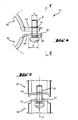
- FIGS. 4 and 5 only shown in a section pipe clamp 41 has a first clamp bracket 42 with a projecting flange 44 having an opening 47 with a circumferential collar and an internal thread for the clamping screw 6. Further, the clamp 41 has a second clamp bracket 52 with a projecting flange 54, in which a slot is provided as a passage opening 58 for the clamping screw 6.
- the passage opening 58 has a in one of the clamping screws 6 and 7 spanned plane extending dimension G, which has a diameter D of the clamping screw 6 exceeding clear width.
- the clamp 41 comprises a resilient element 61 in the form of a circumferentially closed band portion which surrounds the clamping screw 6 guided through the passage opening 58 and on the other hand, the free end of the flange 54 of the second clamp strap 52 and thereby elastically holds the clamping screw 6 in the passage opening 58 ,
- the resilient element 61 acts in the plane defined by the clamping screws 6 and 7 level E.
Landscapes
- Engineering & Computer Science (AREA)
- General Engineering & Computer Science (AREA)
- Mechanical Engineering (AREA)
- Clamps And Clips (AREA)
Claims (6)
- Collier à tube comprenant un premier (12 ; 42) et un second étrier de collier (22 ; 52), lesquels peuvent être reliés l'un à l'autre, par l'intermédiaire de brides (14, 15, 24, 25 ; 44, 54) dépassant à chacune de leurs extrémités, au moyen de deux vis de serrage (6, 7), deux brides (14, 15 ; 44) comportant une ouverture (17 ; 47) pour les vis de serrage (6, 7), une bride (25) opposée à une bride (15) comportant l'ouverture (17) comportant une ouverture d'introduction ouverte latéralement (26), et l'autre bride (24 ; 54) opposée à la bride (14) comportant l'ouverture (17) comportant une ouverture traversante (28 ; 58), laquelle présente, dans un plan (E) défini par les vis de serrage (6, 7), une dimension (F ; G) avec une ouverture libre supérieure au diamètre (D) de la vis de serrage (6), caractérisé en ce que la vis de serrage (6) traversant l'ouverture traversante (28 ; 58) est maintenue élastiquement dans L'ouverture traversante (28 ; 58) par un élément de ressort (31 ; 61).
- Collier à tube selon la revendication 1, caractérisé en ce que l'élément de ressort (61) est une portion de bande qui entoure au moins par endroits la vis de serrage (6) et un des étriers de collier (52).
- Collier à tube selon la revendication 2, caractérisé en ce que la portion de bande pressente une circonférence fermée.
- Collier à tube selon la revendication 1, caractérisé en ce que l'élément de ressort (31) est conformé en manchon et est disposé dans l'ouverture traversante (28).
- Collier à tube selon la revendication 4, caractérisé en ce que l'élément de ressort (31) est pourvu d'une rainure s'étendant radialement (32) pour enserrer au moins par endroits le bord de l'ouverture traversante (28).
- Collier à tube selon la revendication 4 ou 5, caractérisé en ce que l'ouverture traversante (28 ; 58) comportant l'élément de ressort (31 ; 61) et l'ouverture d'introduction (26) sont ménagées dans les brides (24, 25 ; 54) d'un étrier de collier (22 ; 52).
Applications Claiming Priority (1)
| Application Number | Priority Date | Filing Date | Title |
|---|---|---|---|
| DE200710000034 DE102007000034A1 (de) | 2007-01-25 | 2007-01-25 | Rohrschelle |
Publications (2)
| Publication Number | Publication Date |
|---|---|
| EP1950480A1 EP1950480A1 (fr) | 2008-07-30 |
| EP1950480B1 true EP1950480B1 (fr) | 2009-07-15 |
Family
ID=39315205
Family Applications (1)
| Application Number | Title | Priority Date | Filing Date |
|---|---|---|---|
| EP20080100533 Active EP1950480B1 (fr) | 2007-01-25 | 2008-01-16 | Collier de serrage pour tuyaux |
Country Status (3)
| Country | Link |
|---|---|
| EP (1) | EP1950480B1 (fr) |
| DE (2) | DE102007000034A1 (fr) |
| ES (1) | ES2327017T3 (fr) |
Cited By (1)
| Publication number | Priority date | Publication date | Assignee | Title |
|---|---|---|---|---|
| EP3163144A1 (fr) | 2015-10-27 | 2017-05-03 | HILTI Aktiengesellschaft | Dispositif, de préférence collier, comprenant un mécanisme de fermeture doté de rainures de guidage |
Families Citing this family (5)
| Publication number | Priority date | Publication date | Assignee | Title |
|---|---|---|---|---|
| NL2008229C2 (en) * | 2012-02-03 | 2013-08-06 | Walraven Holding Bv J Van | Pipe clip. |
| US10393290B2 (en) | 2017-05-22 | 2019-08-27 | Erico International Corporation | Clamp for circular objects |
| US11371630B2 (en) | 2019-03-29 | 2022-06-28 | ASC Engineered Solutions, LLC | Pivot clip |
| CN113828995A (zh) * | 2021-09-23 | 2021-12-24 | 沪东中华造船(集团)有限公司 | 一种用于管子对中及固定的装置 |
| CN114263831B (zh) * | 2021-12-08 | 2024-03-22 | 杭州海康威视数字技术股份有限公司 | 用于球机吊装的安装结构 |
Family Cites Families (8)
| Publication number | Priority date | Publication date | Assignee | Title |
|---|---|---|---|---|
| DE4124122A1 (de) * | 1991-07-20 | 1993-01-21 | Wolfgang Halpaus | Vorrichtung zur verbindung zweier bauteile |
| ES2120802T3 (es) * | 1995-08-25 | 1998-11-01 | Hilti Ag | Abrazadera para tubos. |
| DE29602102U1 (de) | 1996-02-02 | 1996-03-14 | Mefa-Dübelfabrik Friedrich Krätzer GmbH & Co, 74635 Kupferzell | Rohrschelle mit Verrastung |
| DE29818912U1 (de) * | 1998-10-23 | 1998-12-24 | Fischer Artur Werke Gmbh | Rohrschelle |
| DE19921046A1 (de) * | 1999-05-07 | 2000-11-09 | Mefa Befestigungs Und Montages | Rohrschelle |
| DE10003183A1 (de) * | 2000-01-25 | 2001-08-02 | Wolfgang Halpaus | Rohrschelle |
| DE20017277U1 (de) * | 2000-10-07 | 2001-02-22 | Sw Stanzwerk Glarus Ag, Glarus | Rohrschelle |
| DE102005002235B4 (de) * | 2005-01-18 | 2020-03-26 | Secura Services Ag | Rohrschelle |
-
2007
- 2007-01-25 DE DE200710000034 patent/DE102007000034A1/de not_active Withdrawn
-
2008
- 2008-01-16 ES ES08100533T patent/ES2327017T3/es active Active
- 2008-01-16 DE DE200850000052 patent/DE502008000052D1/de active Active
- 2008-01-16 EP EP20080100533 patent/EP1950480B1/fr active Active
Cited By (2)
| Publication number | Priority date | Publication date | Assignee | Title |
|---|---|---|---|---|
| EP3163144A1 (fr) | 2015-10-27 | 2017-05-03 | HILTI Aktiengesellschaft | Dispositif, de préférence collier, comprenant un mécanisme de fermeture doté de rainures de guidage |
| WO2017072005A1 (fr) | 2015-10-27 | 2017-05-04 | Hilti Aktiengesellschaft | Dispositif, de préférence collier pour tuyau, comprenant un mécanisme de fermeture doté de canaux de guidage |
Also Published As
| Publication number | Publication date |
|---|---|
| ES2327017T3 (es) | 2009-10-22 |
| DE502008000052D1 (de) | 2009-08-27 |
| EP1950480A1 (fr) | 2008-07-30 |
| DE102007000034A1 (de) | 2008-09-04 |
Similar Documents
| Publication | Publication Date | Title |
|---|---|---|
| EP1852643B1 (fr) | Collier destiné à la fixation d'un objet tubulaire | |
| EP0975908B1 (fr) | Collier de serrage pour tuyau | |
| DE102006048336B4 (de) | Schlauchschelle | |
| EP1950480B1 (fr) | Collier de serrage pour tuyaux | |
| EP3423742B1 (fr) | Collier profilé | |
| DE202007019445U1 (de) | Schlauchklemme | |
| EP0508050A2 (fr) | Collier du support avec charniere | |
| DE102017110629B4 (de) | Positioniereinrichtung für eine Federbandschelle | |
| EP2839197A1 (fr) | Courroie de serrage et accouplement pour la liaison à force de tuyaux, en particulier de tuyaux à extrémité lisse | |
| DE102016123388A1 (de) | Profilschelle | |
| EP3430301B1 (fr) | Collier de serrage | |
| EP1950479B1 (fr) | Collier | |
| EP0769647B1 (fr) | Collier de serrage pour la fixation d'un tuyau | |
| EP3500786B1 (fr) | Griffe de fixation | |
| WO2019211053A1 (fr) | Collier de serrage | |
| EP0769649B1 (fr) | Connexion de tuyaux utilisant des colliers de serrage | |
| DE3346423A1 (de) | Rohrschelle | |
| DE10249474A1 (de) | Verbindung einer Schelle mit einem Schlauch zur Vorpositionierung der Schelle | |
| EP0897079A1 (fr) | Collier de serrage pour tuyaux | |
| WO2011012191A1 (fr) | Collier | |
| EP4493849A1 (fr) | Collier profilé | |
| EP2037164A2 (fr) | Collier de serrage | |
| DE102019109518A1 (de) | Rohrschelle | |
| DE10217750B4 (de) | Schelle mit geschlitzten Bandschlaufen zum Einhängen eines Verschlusses | |
| EP1916463B1 (fr) | Collier de tuyau |
Legal Events
| Date | Code | Title | Description |
|---|---|---|---|
| PUAI | Public reference made under article 153(3) epc to a published international application that has entered the european phase |
Free format text: ORIGINAL CODE: 0009012 |
|
| AK | Designated contracting states |
Kind code of ref document: A1 Designated state(s): AT BE BG CH CY CZ DE DK EE ES FI FR GB GR HR HU IE IS IT LI LT LU LV MC MT NL NO PL PT RO SE SI SK TR |
|
| AX | Request for extension of the european patent |
Extension state: AL BA MK RS |
|
| 17P | Request for examination filed |
Effective date: 20090130 |
|
| GRAP | Despatch of communication of intention to grant a patent |
Free format text: ORIGINAL CODE: EPIDOSNIGR1 |
|
| AKX | Designation fees paid |
Designated state(s): AT BE BG CH CY CZ DE DK EE ES FI FR GB GR HR HU IE IS IT LI LT LU LV MC MT NL NO PL PT RO SE SI SK TR |
|
| GRAS | Grant fee paid |
Free format text: ORIGINAL CODE: EPIDOSNIGR3 |
|
| GRAA | (expected) grant |
Free format text: ORIGINAL CODE: 0009210 |
|
| AK | Designated contracting states |
Kind code of ref document: B1 Designated state(s): AT BE BG CH CY CZ DE DK EE ES FI FR GB GR HR HU IE IS IT LI LT LU LV MC MT NL NO PL PT RO SE SI SK TR |
|
| REG | Reference to a national code |
Ref country code: GB Ref legal event code: FG4D Free format text: NOT ENGLISH Ref country code: CH Ref legal event code: EP |
|
| REG | Reference to a national code |
Ref country code: IE Ref legal event code: FG4D |
|
| REF | Corresponds to: |
Ref document number: 502008000052 Country of ref document: DE Date of ref document: 20090827 Kind code of ref document: P |
|
| REG | Reference to a national code |
Ref country code: ES Ref legal event code: FG2A Ref document number: 2327017 Country of ref document: ES Kind code of ref document: T3 |
|
| NLV1 | Nl: lapsed or annulled due to failure to fulfill the requirements of art. 29p and 29m of the patents act | ||
| PG25 | Lapsed in a contracting state [announced via postgrant information from national office to epo] |
Ref country code: FI Free format text: LAPSE BECAUSE OF FAILURE TO SUBMIT A TRANSLATION OF THE DESCRIPTION OR TO PAY THE FEE WITHIN THE PRESCRIBED TIME-LIMIT Effective date: 20090715 Ref country code: SE Free format text: LAPSE BECAUSE OF FAILURE TO SUBMIT A TRANSLATION OF THE DESCRIPTION OR TO PAY THE FEE WITHIN THE PRESCRIBED TIME-LIMIT Effective date: 20090715 Ref country code: IS Free format text: LAPSE BECAUSE OF FAILURE TO SUBMIT A TRANSLATION OF THE DESCRIPTION OR TO PAY THE FEE WITHIN THE PRESCRIBED TIME-LIMIT Effective date: 20091115 Ref country code: NO Free format text: LAPSE BECAUSE OF FAILURE TO SUBMIT A TRANSLATION OF THE DESCRIPTION OR TO PAY THE FEE WITHIN THE PRESCRIBED TIME-LIMIT Effective date: 20091015 Ref country code: LT Free format text: LAPSE BECAUSE OF FAILURE TO SUBMIT A TRANSLATION OF THE DESCRIPTION OR TO PAY THE FEE WITHIN THE PRESCRIBED TIME-LIMIT Effective date: 20090715 |
|
| REG | Reference to a national code |
Ref country code: IE Ref legal event code: FD4D |
|
| PG25 | Lapsed in a contracting state [announced via postgrant information from national office to epo] |
Ref country code: LV Free format text: LAPSE BECAUSE OF FAILURE TO SUBMIT A TRANSLATION OF THE DESCRIPTION OR TO PAY THE FEE WITHIN THE PRESCRIBED TIME-LIMIT Effective date: 20090715 Ref country code: HR Free format text: LAPSE BECAUSE OF FAILURE TO SUBMIT A TRANSLATION OF THE DESCRIPTION OR TO PAY THE FEE WITHIN THE PRESCRIBED TIME-LIMIT Effective date: 20090715 Ref country code: SI Free format text: LAPSE BECAUSE OF FAILURE TO SUBMIT A TRANSLATION OF THE DESCRIPTION OR TO PAY THE FEE WITHIN THE PRESCRIBED TIME-LIMIT Effective date: 20090715 Ref country code: PL Free format text: LAPSE BECAUSE OF FAILURE TO SUBMIT A TRANSLATION OF THE DESCRIPTION OR TO PAY THE FEE WITHIN THE PRESCRIBED TIME-LIMIT Effective date: 20090715 Ref country code: NL Free format text: LAPSE BECAUSE OF FAILURE TO SUBMIT A TRANSLATION OF THE DESCRIPTION OR TO PAY THE FEE WITHIN THE PRESCRIBED TIME-LIMIT Effective date: 20090715 |
|
| PG25 | Lapsed in a contracting state [announced via postgrant information from national office to epo] |
Ref country code: BG Free format text: LAPSE BECAUSE OF FAILURE TO SUBMIT A TRANSLATION OF THE DESCRIPTION OR TO PAY THE FEE WITHIN THE PRESCRIBED TIME-LIMIT Effective date: 20091015 |
|
| PG25 | Lapsed in a contracting state [announced via postgrant information from national office to epo] |
Ref country code: IE Free format text: LAPSE BECAUSE OF FAILURE TO SUBMIT A TRANSLATION OF THE DESCRIPTION OR TO PAY THE FEE WITHIN THE PRESCRIBED TIME-LIMIT Effective date: 20090715 Ref country code: CZ Free format text: LAPSE BECAUSE OF FAILURE TO SUBMIT A TRANSLATION OF THE DESCRIPTION OR TO PAY THE FEE WITHIN THE PRESCRIBED TIME-LIMIT Effective date: 20090715 Ref country code: EE Free format text: LAPSE BECAUSE OF FAILURE TO SUBMIT A TRANSLATION OF THE DESCRIPTION OR TO PAY THE FEE WITHIN THE PRESCRIBED TIME-LIMIT Effective date: 20090715 Ref country code: RO Free format text: LAPSE BECAUSE OF FAILURE TO SUBMIT A TRANSLATION OF THE DESCRIPTION OR TO PAY THE FEE WITHIN THE PRESCRIBED TIME-LIMIT Effective date: 20090715 Ref country code: DK Free format text: LAPSE BECAUSE OF FAILURE TO SUBMIT A TRANSLATION OF THE DESCRIPTION OR TO PAY THE FEE WITHIN THE PRESCRIBED TIME-LIMIT Effective date: 20090715 |
|
| PLBE | No opposition filed within time limit |
Free format text: ORIGINAL CODE: 0009261 |
|
| STAA | Information on the status of an ep patent application or granted ep patent |
Free format text: STATUS: NO OPPOSITION FILED WITHIN TIME LIMIT |
|
| PG25 | Lapsed in a contracting state [announced via postgrant information from national office to epo] |
Ref country code: SK Free format text: LAPSE BECAUSE OF FAILURE TO SUBMIT A TRANSLATION OF THE DESCRIPTION OR TO PAY THE FEE WITHIN THE PRESCRIBED TIME-LIMIT Effective date: 20090715 |
|
| 26N | No opposition filed |
Effective date: 20100416 |
|
| BERE | Be: lapsed |
Owner name: HILTI AKTIENGESELLSCHAFT Effective date: 20100131 |
|
| PG25 | Lapsed in a contracting state [announced via postgrant information from national office to epo] |
Ref country code: MC Free format text: LAPSE BECAUSE OF NON-PAYMENT OF DUE FEES Effective date: 20100131 |
|
| PG25 | Lapsed in a contracting state [announced via postgrant information from national office to epo] |
Ref country code: GR Free format text: LAPSE BECAUSE OF FAILURE TO SUBMIT A TRANSLATION OF THE DESCRIPTION OR TO PAY THE FEE WITHIN THE PRESCRIBED TIME-LIMIT Effective date: 20091016 |
|
| PG25 | Lapsed in a contracting state [announced via postgrant information from national office to epo] |
Ref country code: BE Free format text: LAPSE BECAUSE OF NON-PAYMENT OF DUE FEES Effective date: 20100131 |
|
| PG25 | Lapsed in a contracting state [announced via postgrant information from national office to epo] |
Ref country code: MT Free format text: LAPSE BECAUSE OF FAILURE TO SUBMIT A TRANSLATION OF THE DESCRIPTION OR TO PAY THE FEE WITHIN THE PRESCRIBED TIME-LIMIT Effective date: 20090715 |
|
| PG25 | Lapsed in a contracting state [announced via postgrant information from national office to epo] |
Ref country code: CY Free format text: LAPSE BECAUSE OF FAILURE TO SUBMIT A TRANSLATION OF THE DESCRIPTION OR TO PAY THE FEE WITHIN THE PRESCRIBED TIME-LIMIT Effective date: 20090715 |
|
| PG25 | Lapsed in a contracting state [announced via postgrant information from national office to epo] |
Ref country code: LU Free format text: LAPSE BECAUSE OF NON-PAYMENT OF DUE FEES Effective date: 20100116 Ref country code: PT Free format text: LAPSE BECAUSE OF FAILURE TO SUBMIT A TRANSLATION OF THE DESCRIPTION OR TO PAY THE FEE WITHIN THE PRESCRIBED TIME-LIMIT Effective date: 20091215 Ref country code: HU Free format text: LAPSE BECAUSE OF FAILURE TO SUBMIT A TRANSLATION OF THE DESCRIPTION OR TO PAY THE FEE WITHIN THE PRESCRIBED TIME-LIMIT Effective date: 20100116 |
|
| PG25 | Lapsed in a contracting state [announced via postgrant information from national office to epo] |
Ref country code: TR Free format text: LAPSE BECAUSE OF FAILURE TO SUBMIT A TRANSLATION OF THE DESCRIPTION OR TO PAY THE FEE WITHIN THE PRESCRIBED TIME-LIMIT Effective date: 20090715 |
|
| REG | Reference to a national code |
Ref country code: FR Ref legal event code: PLFP Year of fee payment: 9 |
|
| REG | Reference to a national code |
Ref country code: FR Ref legal event code: PLFP Year of fee payment: 10 |
|
| REG | Reference to a national code |
Ref country code: FR Ref legal event code: PLFP Year of fee payment: 11 |
|
| REG | Reference to a national code |
Ref country code: CH Ref legal event code: U11 Free format text: ST27 STATUS EVENT CODE: U-0-0-U10-U11 (AS PROVIDED BY THE NATIONAL OFFICE) Effective date: 20260201 |
|
| PGFP | Annual fee paid to national office [announced via postgrant information from national office to epo] |
Ref country code: GB Payment date: 20260123 Year of fee payment: 19 |
|
| PGFP | Annual fee paid to national office [announced via postgrant information from national office to epo] |
Ref country code: ES Payment date: 20260227 Year of fee payment: 19 |
|
| PGFP | Annual fee paid to national office [announced via postgrant information from national office to epo] |
Ref country code: DE Payment date: 20260121 Year of fee payment: 19 |
|
| PGFP | Annual fee paid to national office [announced via postgrant information from national office to epo] |
Ref country code: AT Payment date: 20260122 Year of fee payment: 19 |
|
| PGFP | Annual fee paid to national office [announced via postgrant information from national office to epo] |
Ref country code: IT Payment date: 20260126 Year of fee payment: 19 |
|
| PGFP | Annual fee paid to national office [announced via postgrant information from national office to epo] |
Ref country code: FR Payment date: 20260123 Year of fee payment: 19 |
|
| PGFP | Annual fee paid to national office [announced via postgrant information from national office to epo] |
Ref country code: CH Payment date: 20260201 Year of fee payment: 19 |