EP1950545A2 - Arrangement d'excitation et de lecture d'un capteur de couple Villari pour arbres magnétostrictives - Google Patents
Arrangement d'excitation et de lecture d'un capteur de couple Villari pour arbres magnétostrictives Download PDFInfo
- Publication number
- EP1950545A2 EP1950545A2 EP08100542A EP08100542A EP1950545A2 EP 1950545 A2 EP1950545 A2 EP 1950545A2 EP 08100542 A EP08100542 A EP 08100542A EP 08100542 A EP08100542 A EP 08100542A EP 1950545 A2 EP1950545 A2 EP 1950545A2
- Authority
- EP
- European Patent Office
- Prior art keywords
- sensor according
- sensor
- pole pieces
- shaft
- bobbins
- Prior art date
- Legal status (The legal status is an assumption and is not a legal conclusion. Google has not performed a legal analysis and makes no representation as to the accuracy of the status listed.)
- Withdrawn
Links
- 230000005284 excitation Effects 0.000 title claims description 18
- 239000000463 material Substances 0.000 claims description 21
- 239000000696 magnetic material Substances 0.000 claims description 6
- 230000006835 compression Effects 0.000 claims description 5
- 238000007906 compression Methods 0.000 claims description 5
- XEEYBQQBJWHFJM-UHFFFAOYSA-N Iron Chemical compound [Fe] XEEYBQQBJWHFJM-UHFFFAOYSA-N 0.000 claims description 4
- 238000009827 uniform distribution Methods 0.000 claims description 4
- 229920000642 polymer Polymers 0.000 claims description 3
- 239000002131 composite material Substances 0.000 claims description 2
- 238000001746 injection moulding Methods 0.000 claims description 2
- 229910052742 iron Inorganic materials 0.000 claims description 2
- 229910000859 α-Fe Inorganic materials 0.000 claims description 2
- 241001137251 Corvidae Species 0.000 claims 1
- 238000007731 hot pressing Methods 0.000 claims 1
- 235000015108 pies Nutrition 0.000 claims 1
- 230000000694 effects Effects 0.000 abstract description 6
- 238000013461 design Methods 0.000 abstract description 4
- 230000004907 flux Effects 0.000 description 13
- 238000010586 diagram Methods 0.000 description 5
- 238000004519 manufacturing process Methods 0.000 description 4
- 238000000034 method Methods 0.000 description 3
- 230000035699 permeability Effects 0.000 description 3
- 239000000758 substrate Substances 0.000 description 3
- 230000007423 decrease Effects 0.000 description 2
- 238000013459 approach Methods 0.000 description 1
- 239000011248 coating agent Substances 0.000 description 1
- 238000000576 coating method Methods 0.000 description 1
- 238000005094 computer simulation Methods 0.000 description 1
- 238000009795 derivation Methods 0.000 description 1
- 238000005516 engineering process Methods 0.000 description 1
- 230000003116 impacting effect Effects 0.000 description 1
- 238000005259 measurement Methods 0.000 description 1
- 238000012986 modification Methods 0.000 description 1
- 230000004048 modification Effects 0.000 description 1
- 239000012811 non-conductive material Substances 0.000 description 1
- 230000000704 physical effect Effects 0.000 description 1
- 238000004088 simulation Methods 0.000 description 1
- 238000004804 winding Methods 0.000 description 1
Images
Classifications
-
- G—PHYSICS
- G01—MEASURING; TESTING
- G01L—MEASURING FORCE, STRESS, TORQUE, WORK, MECHANICAL POWER, MECHANICAL EFFICIENCY, OR FLUID PRESSURE
- G01L3/00—Measuring torque, work, mechanical power, or mechanical efficiency, in general
- G01L3/02—Rotary-transmission dynamometers
- G01L3/04—Rotary-transmission dynamometers wherein the torque-transmitting element comprises a torsionally-flexible shaft
- G01L3/10—Rotary-transmission dynamometers wherein the torque-transmitting element comprises a torsionally-flexible shaft involving electric or magnetic means for indicating
- G01L3/101—Rotary-transmission dynamometers wherein the torque-transmitting element comprises a torsionally-flexible shaft involving electric or magnetic means for indicating involving magnetic or electromagnetic means
- G01L3/102—Rotary-transmission dynamometers wherein the torque-transmitting element comprises a torsionally-flexible shaft involving electric or magnetic means for indicating involving magnetic or electromagnetic means involving magnetostrictive means
-
- G—PHYSICS
- G01—MEASURING; TESTING
- G01L—MEASURING FORCE, STRESS, TORQUE, WORK, MECHANICAL POWER, MECHANICAL EFFICIENCY, OR FLUID PRESSURE
- G01L3/00—Measuring torque, work, mechanical power, or mechanical efficiency, in general
- G01L3/02—Rotary-transmission dynamometers
- G01L3/04—Rotary-transmission dynamometers wherein the torque-transmitting element comprises a torsionally-flexible shaft
- G01L3/10—Rotary-transmission dynamometers wherein the torque-transmitting element comprises a torsionally-flexible shaft involving electric or magnetic means for indicating
- G01L3/101—Rotary-transmission dynamometers wherein the torque-transmitting element comprises a torsionally-flexible shaft involving electric or magnetic means for indicating involving magnetic or electromagnetic means
- G01L3/105—Rotary-transmission dynamometers wherein the torque-transmitting element comprises a torsionally-flexible shaft involving electric or magnetic means for indicating involving magnetic or electromagnetic means involving inductive means
Definitions
- the present invention relates to Villari torque sensor excitation and pickup arrangement for magnetrostrictive shafts.
- Applying a magnetic field causes stress that changes the physical properties of a magnetostrictive material.
- the reverse is also true: applying stress to a magnetostrictive material changes its magnetic properties (e.g., magnetic permeability). This is called the Villari effect.
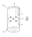
- FIG. 1 is a schematic diagram of a Four-Branch Torque Sensor, generally indicated by reference numeral 100, known in the prior art.
- Sensor 100 is of the type set forth in the Fleming literature.
- a shaft 110 is driven by an engine, represented by arrow 120 to drive a load, represented by arrow 122.
- Shaft 110 is subject to rotation ⁇ due to torque applied to it.
- Principle stress lines of compression and tension are represented by dashed lines 112 and 114, respectively.
- Sensor 100 detects changes in inductance along principal axes of the sensor.
- the four branches each comprise a sensing pole 101 affixed to shaft 110. The four branches are required to force the sensing flux along the principal axes.
- a disadvantage of this arrangement is that it senses inductance changes within only a portion of the shaft circumference making the measurements more sensitive to circumferential inhomogeneities. Also it is very sensitive to variations in air gap between the four sensing poles and the adjacent points on the shaft.
- the inventions described and/or claimed herein relate to novel torque sensor topologies that use high frequency alternating magnetic fields and the Villari effect to determine the state of stress/strain inside a shaft made of a magnetostrictive material for the purpose of measuring torque.
- the inventions relate to various design elements for the sensor and shaft including but not limited to desirable magnetic, electric and structural properties for various elements of the sensor.
- Figure 1 Prior Art illustrates a prior art arrangement of a Four Branch torque sensor which detects changes in inductance along compression and tension axes of a shaft.
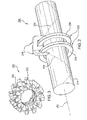
- Figure 2 is a schematic diagram of a simple sensor arrangement illustrating a concept of the inventions described and/or claimed herein.
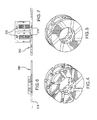
- Figure 3 illustrates a sensor arrangement according to the inventions and based on the simple arrangement shown in figure 2 . It shows skewed sensor poles straddling cylindrical coil bobbins.
- Figure 4 illustrates a bobbin arrangement for a partially constructed sensor according to another embodiment of a sensor according to the inventions
- Figure 5 is a diagram of an assembled sensor based on the bobbin structure shown in Figure 4 .
- Figures 6 and 7 are idealized cross-sections of sensor arrangement embodiments. Cross-section cuts are taken in the middle of the poles in order to show the flux paths. The two cuts are approximately 45 degrees from one another and are joined together at the interface between two adjacent poles to give a planar representation.
- Figure 6 corresponds to a torque sensor operating at high frequencies and
- Figure 7 illustrates a sensor design for low to medium frequencies.
- inventions described and/or claimed herein are directed to various sensor arrangements having cylindrical excitation and sensing coils that can be used with shafts having a cylindrically uniform distribution of magnetostrictive material without any surface modifications such as chevrons, etc., that force flux along the principal axes.
- FIG. 2 is a schematic diagram of a simple sensor arrangement illustrating a concept of the inventions described and/or claimed herein.
- a sensor 200 includes skewed sensor pole pieces 210 that straddle cylindrical coil bobbins 222.
- the sensor has a unique pole structure that forces flux along the principal axes.
- Discrete pole pieces 210 are skewed with respect to a shaft axis 212 of a shaft 214 and that straddle concentric excitation coils 216 and sensing coils 230, the excitation coils 216 and sensing coils 230 being wound on coil bobbins 222.
- Each bobbin contains one excitation coil and one sensing coil.
- pole pieces 210 must be fabricated using a soft magnetic material, desirably one with low eddy current and hysteresis losses. For high frequency applications the pole pieces 210 should be made of a ferrite or equivalent low loss type of material.
- the excitation coils 216 and sensing coils 230 are wound coaxially in two bobbins 222, one for each set of pole pieces 210.
- Figure 3 illustrates a sensor arrangement utilizing the principles illustrated in Figure 2 . Only the sensor 200 is shown in the figure (shaft 214 is not shown). In the Figure 3 arrangement there are 12 pairs of pole pieces 210. Each pole piece pair straddles two bobbins 222, one containing the excitation coil 216 and the other containing the sensing coil 230. The sensor arrangement can be fitted to a shaft
- Figure 4 is a perspective view of a partially constructed sensor arrangement. This figure shows a coil bobbin arrangement prepared for the winding of excitation and sensing coils. After the cols are wound, pole pieces 210 are then inserted over the bobbins 222 such that they straddle them as shown.
- the bobbins 222 can be molded out of a polymer or other suitable non-magnetic and non-conductive material to form a structure into which the coils are wound.
- the bobbins are fabricated from a non-conducting and non-magnetic material.
- a suitable material is a polymer.
- Figure 5 is a diagram of an assembled sensor based on the arrangement shown in Figure 4 .
- Excitation coils 216 and 230 have been wound on bobbins 222 and pole pieces 210 have been slid into place in the spaces provided by the bobbin configuration.
- the pole pieces can be fabricated as discrete pieces or they can be formed by injection molding using Soft Magnetic Composite (SMC) or other plastic iron type materials.
- SMC Soft Magnetic Composite
- Figures 6 and 7 show a axial slices through two different sensor arrangements.
- the cuts are taken in the middle of the poles in order to show the flux paths.
- the two cuts are approximately 45 degrees from one another. These are joined together at the interface between two adjacent poles to give a planar representation.
- Figure 6 shows an embodiment of a torque sensor operating at high frequencies (the higher the frequency, the thinner the sensor's radial height). If the frequency is high enough the sensor can be implemented on a flexible substrate (flexible printed circuit).
- Figure 7 shows an embodiment of a sensor arrangement for low to medium frequencies. What constitutes low, medium, or high frequency depends on the materials used and fabrication methods but typical numbers would be 1kHz, 10kHz, and above 100kHz, respectively.
- the required cross-section size shrinks with increasing frequency because the coil voltage is a function of the product of the magnetic flux and electrical frequency. As the frequency goes up the flux (and hence cross-sectional area) can be reduced for a fixed voltage. Moreover, the skin depth of the flux going through the shaft also decreases with increasing frequency, and therefore the pole cross-sectional areas can be reduced without impacting the sensor output.
- the assembled sensor would be slipped over shaft 214 having a suitable magnetostrictive material on its surface such that it responds via the Villari effect when subjected to torque.
- the excitation coils 216 and sensing coils 230 are connected to external circuitry in a known manner, such as described in the Fleming literature cited in the BACKGROUND section of this document.
- FIG. 6 A view along an axial slice of the sensor is shown in Figures 6 and 7 showing the flux paths and the coil layout.
- the skin depth in the surface 240 of shaft 214 will be very small and therefore the total flux small. Under these conditions the cross-sectional area of the poles can be significantly reduced resulting in the low profile package shown in Figure 6 .
Landscapes
- Physics & Mathematics (AREA)
- Electromagnetism (AREA)
- General Physics & Mathematics (AREA)
- Force Measurement Appropriate To Specific Purposes (AREA)
Applications Claiming Priority (1)
| Application Number | Priority Date | Filing Date | Title |
|---|---|---|---|
| US11/657,230 US20080173102A1 (en) | 2007-01-24 | 2007-01-24 | Villari torque sensor excitation and pickup arrangement for magnetrostrictive shafts |
Publications (2)
| Publication Number | Publication Date |
|---|---|
| EP1950545A2 true EP1950545A2 (fr) | 2008-07-30 |
| EP1950545A3 EP1950545A3 (fr) | 2010-06-30 |
Family
ID=39301765
Family Applications (1)
| Application Number | Title | Priority Date | Filing Date |
|---|---|---|---|
| EP08100542A Withdrawn EP1950545A3 (fr) | 2007-01-24 | 2008-01-16 | Arrangement d'excitation et de lecture d'un capteur de couple Villari pour arbres magnétostrictives |
Country Status (2)
| Country | Link |
|---|---|
| US (1) | US20080173102A1 (fr) |
| EP (1) | EP1950545A3 (fr) |
Cited By (5)
| Publication number | Priority date | Publication date | Assignee | Title |
|---|---|---|---|---|
| US10983019B2 (en) | 2019-01-10 | 2021-04-20 | Ka Group Ag | Magnetoelastic type torque sensor with temperature dependent error compensation |
| US11486776B2 (en) | 2016-12-12 | 2022-11-01 | Kongsberg Inc. | Dual-band magnetoelastic torque sensor |
| US11821763B2 (en) | 2016-05-17 | 2023-11-21 | Kongsberg Inc. | System, method and object for high accuracy magnetic position sensing |
| US12025521B2 (en) | 2020-02-11 | 2024-07-02 | Brp Megatech Industries Inc. | Magnetoelastic torque sensor with local measurement of ambient magnetic field |
| US12292350B2 (en) | 2019-09-13 | 2025-05-06 | Brp Megatech Industries Inc. | Magnetoelastic torque sensor assembly for reducing magnetic error due to harmonics |
Families Citing this family (9)
| Publication number | Priority date | Publication date | Assignee | Title |
|---|---|---|---|---|
| US8886491B2 (en) * | 2010-04-30 | 2014-11-11 | Hunter Engineering Company | Auto-calibrating wheel balancer force transducer |
| CN102437784A (zh) * | 2011-05-13 | 2012-05-02 | 兰州大学 | 一种基于磁弹性材料的电磁式微驱动器 |
| WO2016140861A1 (fr) * | 2015-02-27 | 2016-09-09 | Mayo Foundation For Medical Education And Research | Système et procédé de surveillance de force mécanique |
| JP6483778B1 (ja) * | 2017-10-11 | 2019-03-13 | シナノケンシ株式会社 | 磁歪式トルク検出センサ |
| JP6961222B2 (ja) * | 2017-12-11 | 2021-11-05 | 多摩川精機株式会社 | 歪みセンサのステータ構造 |
| JP7099699B2 (ja) * | 2018-06-05 | 2022-07-12 | 多摩川精機株式会社 | 透磁率の変化を検出するためのコア構造体および歪み検出装置 |
| JP2019215175A (ja) * | 2018-06-11 | 2019-12-19 | 多摩川精機株式会社 | 歪みセンサのステータ構造 |
| JP7076790B2 (ja) * | 2018-08-22 | 2022-05-30 | 多摩川精機株式会社 | トルクセンサ |
| JP6840208B2 (ja) * | 2019-03-06 | 2021-03-10 | シナノケンシ株式会社 | 磁歪式トルク検出センサ |
Citations (2)
| Publication number | Priority date | Publication date | Assignee | Title |
|---|---|---|---|---|
| US6941824B2 (en) | 2003-04-25 | 2005-09-13 | Delphi Technologies, Inc. | Magnetic force sensor and control circuit for same |
| US6993983B2 (en) | 2002-12-06 | 2006-02-07 | Delphi Technologies, Inc. | Universal magnetostrictive force sensor |
Family Cites Families (22)
| Publication number | Priority date | Publication date | Assignee | Title |
|---|---|---|---|---|
| US3011340A (en) * | 1957-06-26 | 1961-12-05 | Asea Ab | Means for measuring a torsional stress in a shaft of magnetostrictive material |
| US4479390A (en) * | 1983-01-28 | 1984-10-30 | Borg-Warner Corporation | Transducer for measuring torque and/or speed of rotating shaft |
| US4593555A (en) * | 1983-12-16 | 1986-06-10 | Gary W. Krutz | Speed and torque sensor for hydraulic motor |
| JPS60140133A (ja) * | 1983-12-28 | 1985-07-25 | Toyota Central Res & Dev Lab Inc | トルクセンサ |
| US4566338A (en) * | 1984-07-20 | 1986-01-28 | Trw Inc. | Noncontact torque sensor |
| US4896544A (en) * | 1986-12-05 | 1990-01-30 | Mag Dev Inc. | Magnetoelastic torque transducer |
| US4939937A (en) * | 1988-07-21 | 1990-07-10 | Sensortech, L. P. | Magnetostrictive torque sensor |
| KR920010310B1 (ko) * | 1988-12-06 | 1992-11-26 | 미쯔비시덴끼 가부시끼가이샤 | 왜곡 검출 장치 |
| US5208503A (en) * | 1991-04-12 | 1993-05-04 | Hisey Bradner L | Energy-efficient ferromagnetic stator and core apparatus |
| US5591925A (en) * | 1991-07-29 | 1997-01-07 | Garshelis; Ivan J. | Circularly magnetized non-contact power sensor and method for measuring torque and power using same |
| US5442956A (en) * | 1992-06-03 | 1995-08-22 | Trw Inc. | Torque sensor for a power assist steering system |
| JPH06216426A (ja) * | 1992-06-09 | 1994-08-05 | Nippondenso Co Ltd | 磁歪層形成方法およびそれを用いた歪センサ |
| GB9225971D0 (en) * | 1992-12-12 | 1993-02-10 | Penny & Giles Blackwood Ltd | Rotary transducer |
| SE508734C2 (sv) * | 1994-03-30 | 1998-11-02 | Asea Brown Boveri | Magnetoelastisk beröringsfri vridmomentgivare |
| US6779409B1 (en) * | 1997-01-27 | 2004-08-24 | Southwest Research Institute | Measurement of torsional dynamics of rotating shafts using magnetostrictive sensors |
| US7131339B2 (en) * | 1997-01-27 | 2006-11-07 | Southwest Research Institute | Measurement of torsional dynamics of rotating shafts using magnetostrictive sensors |
| JPH11337424A (ja) * | 1998-05-27 | 1999-12-10 | Aisin Seiki Co Ltd | トルクセンサ |
| JPH11344394A (ja) * | 1998-05-29 | 1999-12-14 | Toyota Autom Loom Works Ltd | トルクセンサ |
| US6289748B1 (en) * | 1999-11-23 | 2001-09-18 | Delphi Technologies, Inc. | Shaft torque sensor with no air gap |
| US7210360B2 (en) * | 2003-06-16 | 2007-05-01 | Delphi Technologies, Inc. | Apparatus for sensing position and/or torque |
| US7024946B2 (en) * | 2004-01-23 | 2006-04-11 | Delphi Technologies, Inc. | Assembly for measuring movement of and a torque applied to a shaft |
| US7320255B2 (en) * | 2005-08-12 | 2008-01-22 | Siemens Vdo Automotive Corporation | Torque sensor magnetometer |
-
2007
- 2007-01-24 US US11/657,230 patent/US20080173102A1/en not_active Abandoned
-
2008
- 2008-01-16 EP EP08100542A patent/EP1950545A3/fr not_active Withdrawn
Patent Citations (2)
| Publication number | Priority date | Publication date | Assignee | Title |
|---|---|---|---|---|
| US6993983B2 (en) | 2002-12-06 | 2006-02-07 | Delphi Technologies, Inc. | Universal magnetostrictive force sensor |
| US6941824B2 (en) | 2003-04-25 | 2005-09-13 | Delphi Technologies, Inc. | Magnetic force sensor and control circuit for same |
Non-Patent Citations (5)
| Title |
|---|
| B. LEQUESNE ET AL., UNIVERSAL MAGNETOSTRICTIVE FORCE SENSOR, 16 June 2002 (2002-06-16) |
| T, SCHROEDER; D. MORELLI, FORCE SENSOR AND CONTROL CIRCUIT FOR SAME, 2002 |
| W. J. FLEMING, COMPUTER-MODEL SIMULATION RESULTS FOR THREE MAGNETOSTRICTIVE TORQUE SENSOR DESIGNS, vol. 910857, March 1991 (1991-03-01) |
| W. J. FLEMING, ENGINE SENSORS: STATE OF THE ART, vol. 820904, October 1982 (1982-10-01) |
| W. J. FLEMING, MAGNETOSTRICTIVE TORQUE SENSORS - DERIVATION OF TRANSDUCER MODEL, vol. 890482, pages 81 - 100 |
Cited By (6)
| Publication number | Priority date | Publication date | Assignee | Title |
|---|---|---|---|---|
| US11821763B2 (en) | 2016-05-17 | 2023-11-21 | Kongsberg Inc. | System, method and object for high accuracy magnetic position sensing |
| US11486776B2 (en) | 2016-12-12 | 2022-11-01 | Kongsberg Inc. | Dual-band magnetoelastic torque sensor |
| US10983019B2 (en) | 2019-01-10 | 2021-04-20 | Ka Group Ag | Magnetoelastic type torque sensor with temperature dependent error compensation |
| US12292350B2 (en) | 2019-09-13 | 2025-05-06 | Brp Megatech Industries Inc. | Magnetoelastic torque sensor assembly for reducing magnetic error due to harmonics |
| US12025521B2 (en) | 2020-02-11 | 2024-07-02 | Brp Megatech Industries Inc. | Magnetoelastic torque sensor with local measurement of ambient magnetic field |
| US12281951B2 (en) | 2020-02-11 | 2025-04-22 | Brp Megatech Industries Inc. | Magnetoelastic torque sensor with local measurement of ambient magnetic field |
Also Published As
| Publication number | Publication date |
|---|---|
| EP1950545A3 (fr) | 2010-06-30 |
| US20080173102A1 (en) | 2008-07-24 |
Similar Documents
| Publication | Publication Date | Title |
|---|---|---|
| EP1950545A2 (fr) | Arrangement d'excitation et de lecture d'un capteur de couple Villari pour arbres magnétostrictives | |
| JP6376028B2 (ja) | トルクセンサ | |
| EP1840545A3 (fr) | Capteur de couple et son procédé de fabrication | |
| US20060179959A1 (en) | Magnetostrictive torque sensor | |
| US7584672B2 (en) | Magnetostrictive torque sensor | |
| CN206657708U (zh) | 三相电抗器、电动机驱动装置、功率调节器和机械或装置 | |
| JP3930057B2 (ja) | ソレノイドコイルのための変位測定システム | |
| CN102315008A (zh) | 可变磁阻型旋转变压器及制造其的方法 | |
| US5128614A (en) | Compound core element having a pair of uniaxial anisotropic ferromagnetic cell components with different coercive field strength for a thin film sensor | |
| US8653810B2 (en) | Flexible magnetostrictive sensor | |
| JPH0422830A (ja) | トルクセンサ | |
| JP5133758B2 (ja) | 磁気軸受用位置センサ装置及び磁気軸受装置 | |
| EP1484618A3 (fr) | Sonde à noyau saturable miniature et son procédé de fabrication | |
| US20220020522A1 (en) | Core for torque detection sensor and torque detection sensor | |
| US20220018723A1 (en) | Torque detection sensor | |
| JP3252004B2 (ja) | 磁歪式トルクセンサ | |
| CN100567921C (zh) | 磁致伸缩式负荷传感器 | |
| ITMI950614A1 (it) | Sensore di posizione angolare assoluta di tipo induttivo a riluttanza variabile | |
| JP2022019090A (ja) | トルク検出センサ | |
| JP5303859B2 (ja) | 電線の支持構造 | |
| CN215373838U (zh) | 一种圆筒形直线位移传感器 | |
| JPH0943070A (ja) | 磁歪式トルクセンサ | |
| JP5866515B2 (ja) | 力センサ及びそれを用いた力検知装置 | |
| Sasada et al. | A figure-of-eight flexible pickup coil for a magnetostrictive torque sensor | |
| CN221859777U (zh) | 电磁感应式扭矩传感器 |
Legal Events
| Date | Code | Title | Description |
|---|---|---|---|
| PUAI | Public reference made under article 153(3) epc to a published international application that has entered the european phase |
Free format text: ORIGINAL CODE: 0009012 |
|
| AK | Designated contracting states |
Kind code of ref document: A2 Designated state(s): AT BE BG CH CY CZ DE DK EE ES FI FR GB GR HR HU IE IS IT LI LT LU LV MC MT NL NO PL PT RO SE SI SK TR |
|
| AX | Request for extension of the european patent |
Extension state: AL BA MK RS |
|
| PUAL | Search report despatched |
Free format text: ORIGINAL CODE: 0009013 |
|
| AK | Designated contracting states |
Kind code of ref document: A3 Designated state(s): AT BE BG CH CY CZ DE DK EE ES FI FR GB GR HR HU IE IS IT LI LT LU LV MC MT NL NO PL PT RO SE SI SK TR |
|
| AX | Request for extension of the european patent |
Extension state: AL BA MK RS |
|
| STAA | Information on the status of an ep patent application or granted ep patent |
Free format text: STATUS: THE APPLICATION IS DEEMED TO BE WITHDRAWN |
|
| 18D | Application deemed to be withdrawn |
Effective date: 20100803 |