EP1950715A2 - Verfahren und Vorrichtung zum Sichern eines Raumes gegen Gasexplosionsgefahr - Google Patents
Verfahren und Vorrichtung zum Sichern eines Raumes gegen Gasexplosionsgefahr Download PDFInfo
- Publication number
- EP1950715A2 EP1950715A2 EP07076117A EP07076117A EP1950715A2 EP 1950715 A2 EP1950715 A2 EP 1950715A2 EP 07076117 A EP07076117 A EP 07076117A EP 07076117 A EP07076117 A EP 07076117A EP 1950715 A2 EP1950715 A2 EP 1950715A2
- Authority
- EP
- European Patent Office
- Prior art keywords
- space
- explosion
- warning signal
- security device
- atmosphere
- Prior art date
- Legal status (The legal status is an assumption and is not a legal conclusion. Google has not performed a legal analysis and makes no representation as to the accuracy of the status listed.)
- Granted
Links
- 238000004880 explosion Methods 0.000 title claims abstract description 60
- 238000000034 method Methods 0.000 title claims abstract description 19
- 239000002360 explosive Substances 0.000 claims abstract description 32
- 239000000203 mixture Substances 0.000 claims abstract description 29
- 230000002401 inhibitory effect Effects 0.000 claims abstract description 27
- 239000003795 chemical substances by application Substances 0.000 claims abstract description 26
- 239000000443 aerosol Substances 0.000 claims abstract description 21
- 239000007787 solid Substances 0.000 claims abstract description 15
- 238000002144 chemical decomposition reaction Methods 0.000 claims abstract description 8
- 238000012544 monitoring process Methods 0.000 claims description 9
- 238000005474 detonation Methods 0.000 claims description 4
- 239000003999 initiator Substances 0.000 claims description 4
- 230000007274 generation of a signal involved in cell-cell signaling Effects 0.000 claims description 3
- 230000001771 impaired effect Effects 0.000 claims description 2
- 230000002459 sustained effect Effects 0.000 claims description 2
- 239000007789 gas Substances 0.000 description 53
- 238000012423 maintenance Methods 0.000 description 9
- 230000006378 damage Effects 0.000 description 4
- QVGXLLKOCUKJST-UHFFFAOYSA-N atomic oxygen Chemical compound [O] QVGXLLKOCUKJST-UHFFFAOYSA-N 0.000 description 3
- 238000005259 measurement Methods 0.000 description 3
- 230000015654 memory Effects 0.000 description 3
- 239000001301 oxygen Substances 0.000 description 3
- 229910052760 oxygen Inorganic materials 0.000 description 3
- 230000004044 response Effects 0.000 description 3
- 239000000126 substance Substances 0.000 description 3
- 230000003197 catalytic effect Effects 0.000 description 2
- 239000002826 coolant Substances 0.000 description 2
- 238000000354 decomposition reaction Methods 0.000 description 2
- 238000005553 drilling Methods 0.000 description 2
- 230000006870 function Effects 0.000 description 2
- 239000003112 inhibitor Substances 0.000 description 2
- 238000009434 installation Methods 0.000 description 2
- 238000012986 modification Methods 0.000 description 2
- 230000004048 modification Effects 0.000 description 2
- 206010003497 Asphyxia Diseases 0.000 description 1
- 241001465754 Metazoa Species 0.000 description 1
- CBENFWSGALASAD-UHFFFAOYSA-N Ozone Chemical compound [O-][O+]=O CBENFWSGALASAD-UHFFFAOYSA-N 0.000 description 1
- 208000027418 Wounds and injury Diseases 0.000 description 1
- 238000004891 communication Methods 0.000 description 1
- 238000001816 cooling Methods 0.000 description 1
- 238000001514 detection method Methods 0.000 description 1
- 238000010586 diagram Methods 0.000 description 1
- 230000000694 effects Effects 0.000 description 1
- 231100001261 hazardous Toxicity 0.000 description 1
- 238000002347 injection Methods 0.000 description 1
- 239000007924 injection Substances 0.000 description 1
- 208000014674 injury Diseases 0.000 description 1
- 239000000463 material Substances 0.000 description 1
- 230000010355 oscillation Effects 0.000 description 1
- 230000035945 sensitivity Effects 0.000 description 1
- 238000012360 testing method Methods 0.000 description 1
- 238000009423 ventilation Methods 0.000 description 1
Images

Classifications
-
- G—PHYSICS
- G07—CHECKING-DEVICES
- G07F—COIN-FREED OR LIKE APPARATUS
- G07F19/00—Complete banking systems; Coded card-freed arrangements adapted for dispensing or receiving monies or the like and posting such transactions to existing accounts, e.g. automatic teller machines
- G07F19/20—Automatic teller machines [ATMs]
- G07F19/205—Housing aspects of ATMs
-
- E—FIXED CONSTRUCTIONS
- E05—LOCKS; KEYS; WINDOW OR DOOR FITTINGS; SAFES
- E05G—SAFES OR STRONG-ROOMS FOR VALUABLES; BANK PROTECTION DEVICES; SAFETY TRANSACTION PARTITIONS
- E05G1/00—Safes or strong-rooms for valuables
- E05G1/02—Details
-
- G—PHYSICS
- G07—CHECKING-DEVICES
- G07F—COIN-FREED OR LIKE APPARATUS
- G07F19/00—Complete banking systems; Coded card-freed arrangements adapted for dispensing or receiving monies or the like and posting such transactions to existing accounts, e.g. automatic teller machines
- G07F19/20—Automatic teller machines [ATMs]
-
- E—FIXED CONSTRUCTIONS
- E05—LOCKS; KEYS; WINDOW OR DOOR FITTINGS; SAFES
- E05G—SAFES OR STRONG-ROOMS FOR VALUABLES; BANK PROTECTION DEVICES; SAFETY TRANSACTION PARTITIONS
- E05G1/00—Safes or strong-rooms for valuables
- E05G1/06—Safes or strong-rooms for valuables having provision for multiple compartments
- E05G1/08—Safes or strong-rooms for valuables having provision for multiple compartments secured individually
Definitions
- the invention relates to a method for securing a space against danger of gas explosion, comprising of detecting the composition of the atmosphere in the space and generating a warning signal when the detected composition becomes explosive. Such a method is known and is applied for instance for monitoring spaces in which explosive substances are used.
- the present invention relates particularly to the securing of secure compartments of cash dispensers, deposit safes and the like against the danger of a gas explosion.
- Cash dispensers or deposit safes are generally built into frontages of bank premises. By the nature of their function they are readily accessible and therefore difficult to safeguard. In recent times cash dispensers in particular are being robbed increasingly more often in so-called gas attacks. Using flammable gas or gas mixture and explosives criminals blow a complete cash dispenser out of the wall. For this purpose a hole is made in the cash dispenser, usually in the vicinity of the dispensing opening where the money comes out. A flammable gas or gas mixture is then pumped inside through this hole using a hose. This gas or gas mixture is then caused to explode from a distance with a small explosive or only a detonator, after which the secure compartment of the cash dispenser is opened.
- the invention therefore has for its object to further develop a method of the type described in the preamble such that spaces, and in particular secure compartments, can thereby be secured against danger of gas explosion resulting from the above described criminal practices, without major costly modifications being necessary for this purpose.
- this is achieved in such a method in that an explosion-inhibiting agent is introduced into the space when the warning signal is generated.
- a gas explosion can be efficiently prevented by introducing an explosion inhibitor in this way immediately a potentially explosive concentration of a determined substance is detected in the secured space.
- the detection of explosion hazard and the introduction of an explosion inhibitor can moreover be realized with relatively simple means, even in existing secure compartments.
- the explosion-inhibiting agent is preferably introduced into the space in the form of an aerosol.
- the explosion-inhibiting agent can thus fill the whole space to be secured in a short time.
- the aerosol is formed by chemical decomposition of a solid present in or close to the space, it is possible to suffice with a relatively small quantity of solid which can be easily accommodated in or close to the space to be secured.
- the chemical decomposition can advantageously then be initiated and sustained here by the warning signal.
- the forming of the aerosol can thus also be continued without an outside heat supply.
- the explosion-inhibiting agent preferably binds the potentially explosive elements in the atmosphere in the space. This prevents them from exploding.
- the explosion-inhibiting agent can optionally also have a cooling action, thereby reducing the explosion hazard still further.
- the method is distinguished in that the atmosphere in the space is detonated when the warning signal is generated.
- This detonation can also be combined with the introduction of the explosion-inhibiting agent.
- the explosion-inhibiting agent can for instance be introduced first, and then - if the criminals continue to inject explosive gases into the space, whereby the explosion-inhibiting agent could be displaced - the explosive gases are detonated before they reach a concentration such that an explosion would have serious consequences.
- detonation of the atmosphere in the space is preferably repeated periodically.
- the invention also relates to a device for performing the above described method.
- Devices are already known for securing a space against danger of gas explosion, which are provided with means for detecting the composition of the atmosphere in the space and means connected to the detecting means for generating a warning signal when the detected composition becomes explosive.
- the security device according to the present invention is distinguished from these known devices by means connected controllably to the warning signal-generating means for introducing an explosion-inhibiting agent into the space.
- the explosion inhibitor-introducing means are preferably adapted to introduce an aerosol into the space, and advantageously comprise for this purpose a solid which is present in or close to the space and which can be converted by chemical decomposition into an aerosol.
- a structurally simple and effective security device is then obtained when the explosion inhibitor-introducing means comprise at least one container which is filled with the solid and which comprises an initiator connected to the warning signal-generating means.
- the explosion inhibitor-introducing means preferably comprise a plurality of containers filled with the solid, and the warning signal-generating means comprise a delaying element for each container.
- the individual containers can thus be activated at different points in time after the warning signal has been generated, whereby the explosion-inhibiting agent is dispensed in a number of separate doses. It is hereby possible to prevent the initially formed aerosol being displaced by explosive gas that is injected later.
- the explosion-inhibiting agent is advantageously adapted to bind potentially explosive elements in the atmosphere in the space.
- the security device according to the invention can additionally or instead be distinguished from known devices by means connected controllably to the warning signal-generating means for the purpose of detonating the atmosphere in the space.
- These detonating means are preferably periodically active after receiving the warning signal.
- the detecting means advantageously comprise at least one gas sensor placed in or close to the space.
- Gas sensors are widely available commercially and in many variants. In addition to a high sensitivity, a rapid response time of the gas sensor is particularly important in the present application. For optimum security it is otherwise recommended that the detecting means comprise a plurality of gas sensors placed at different locations in or close to the space.
- the security device can advantageously be provided with means connected for signal generation to the warning signal-generating means for the purpose of monitoring the integrity of the space.
- These monitoring means can for instance comprise a drilling detector or a seismic vibration sensor.
- the warning signal-generating means preferably form part of an electronic control system comprising at least one input connected to the detecting means and at least one output connected to the explosion inhibitor-introducing means. Further functions of the security device can be incorporated in this control system, for instance relating to monitoring of the operation of the device, the lifespan of the components used or the maintenance thereof.
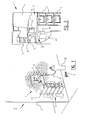
- a cash dispenser 1 ( fig. 1 ) comprises a control panel 3 arranged in an outer wall 2 of a building and internal parts 5 placed in a reinforced space 4 in the building. These internal parts 5 comprise the actual dispensing machine 6 and a secure compartment or safe 40 with a number of cash cassettes 7 therein.
- a hole 9 is here made in cash dispenser 1 using a drill 8. Using a hose 11 a flammable gas or gas mixture G is then pumped inside through this hole 9 from a gas bottle 10. This gas or gas mixture G is then made to explode from a distance using a small explosive or just a detonator, after which cash dispenser 1 is blown out of the wall 2, or at least the secure compartment 40 thereof is blown open.
- a safety device 12 ( fig. 2 ).
- This comprises in the first place means 13 for detecting the composition of the atmosphere in space 4, for instance in the form of one or more gas sensors (only one shown) arranged in space 4 itself or in the immediate vicinity thereof.
- Gas sensors 13 can be highly sensitive industrial sensors for use in high-risk environments, as for instance known in the offshore industry.
- the many types of filter normally used to prevent false alarms can be removed.
- catalytic gas sensors are applied in which use is made of a thermal measurement principle.
- sensors which detect the presence of a possibly explosive gas mixture use can also be made of sensors which compare the composition of the atmosphere in space 4 to a standard atmosphere, generally air.
- An oxygen sensor (not shown here) can for instance be used for this purpose which generates a signal when the oxygen concentration in space 4 clearly deviates from 21%, the value in the standard atmosphere.
- security device 12 comprises means 14 connected to detecting means 13 for the purpose of generating a warning signal when the detected composition becomes explosive.
- these warning signal-generating means 14 form part of an electronic control system which will be elucidated in more detail below.
- security device 12 comprises means 15 connected controllably to the warning signal-generating means 14 for the purpose of introducing an explosion-inhibiting agent into space 4.
- explosion-inhibiting agent is an aerosol A which binds potentially explosive elements in the atmosphere in space 4.
- This aerosol must meet several requirements. It must thus be a means which is not harmful to humans and animals, the environment, the ozone layer or the materials used in cash dispenser 1. In addition, the aerosol may not remove oxygen so as to avoid suffocation hazard.
- the explosion inhibitor-introducing means 15 comprise at least one container 16 filled with a solid 17 which can be converted into the aerosol by chemical decomposition.
- An initiator 18 which is connected to the warning signal-generating means 14 and which initiates and sustains the decomposition reaction of solid 17 is accommodated in this container 16 ( fig. 3A ).
- Container 16 is provided on one side with a weighted base 36 and further has a strengthened side wall 37 and a cover 38 which collapses readily, thereby enabling a targeted delivery of the aerosol.
- a chemical cooling agent 39 is arranged in container 16 between solid 17 and cover 38, whereby heat created during the decomposition of solid 17 into aerosol is absorbed ( fig. 3B ).
- This cooling agent 39 is likewise decomposed here and remains behind in container 16 ( fig. 3C ).
- the aerosol can thus leave container 16 at relatively low temperature, and the aerosol itself does not form a detonation source for the potentially explosive gas mixture in space 4.
- a plurality of containers 16 can be applied in practice which can be arranged at different locations in space 4, at dispensing machine 6 as well as at secure compartment 40. Initiators 18 of these containers can then be energized at different points in time after the first warning signal has been generated, whereby a cascade of aerosol discharges as it were takes place.
- security device 12 can also be provided with means (not shown) for monitoring the integrity of space 4.
- monitoring means which are likewise connected for signal generation to warning signal-generating means 14, can for instance comprise a drilling detector or a seismic vibration sensor.
- warning signal-generating means 14 The signals from the different sensors and/or detectors are converted by the warning signal-generating means 14 into one or more warning or alarm signals. These warning signals serve not only to activate the explosion inhibitor-introducing means 15, but can also be used for instance to alert a control room or to activate an alarm system.
- the warning signal-generating means 14 form part of an electronic control system 19 ( fig. 4 ), which in the shown embodiment has eight inputs I1-I8 and eight outputs O1-O8. Of the eight inputs I1-I8 four are analog inputs I1-I4 connected to detecting means 13, more particularly the gas sensors. In the shown embodiment these analog inputs I1-I4 have a measuring range of 0 to 5 V. In addition, there are two digital alarm inputs I5, I6 and two digital switch inputs I7, I8 for the purpose of switching security device 12 on and off, for instance for maintenance purposes.
- the eight outputs O1-O8 are divided into six alarm outputs 01-06, an error output 07 and a maintenance output 08.
- the six alarm outputs O1-O6 embodied as open collector, at least one O1 is connected to the explosion inhibitor-introducing means 15.
- a plurality of alarm outputs for instance also outputs 05 and 06 can also be connected to the different containers 16.
- the remaining alarm outputs 02-04 are intended to generate warning signals to other equipment, such as for instance an alarm installation at the location of cash dispenser 1 and an alarm dialer which can transmit the warning signal to a central control room.
- One of the alarm outputs I can also be connected to a detonator placed in space 4 which detonates the already injected gas mixture before it can reach a dangerous concentration.
- the electronic control system 19 also comprises on the input side a further two RS-232 ports 20, 21, an I2C bus 22, an SPI bus 23, two terminals 24, 25 for programming and/or updating firmware and a 24 V power connection 26.
- the electronic control system 19 is further provided with five LED outputs L1-L5 and a buzzer output 27.
- the electronic control system 19 comprises different circuits and memories. There is thus a circuit 28 for updating firmware, a self-test circuit 29, a circuit 30 in which the serial number of security device 12 is included, an I2C circuit 31, an erasable programmable read-only memory (EEPROM) 32, a clock circuit 33, a circuit 34 for tracking use and an RS-232 communication circuit 35.
- I2C circuit 31 is here a bus with which security device 12 can be coupled to other systems, for instance a system with which in the case of an attack a dye is sprayed onto the banknotes in the cash dispenser ("Ink & Dye"). Via this bus the memory of electronic control system 19 can also be extended or a display can be connected to the system.
- the six alarm inputs I1-I6 can be configured such that they can generate a warning signal at one or more of the six alarm outputs O1-O6.
- Alarm inputs I1-I6 can each be switched off individually.
- the gas sensors used are catalytic sensors which perform a thermal measurement.
- the sensor When device 12 is switched on, such sensors have a warm-up time in the order of a minute. During this warm-up time the sensor generates a current of about 2 mA. The same current is generated in the case the sensor fails. Under normal conditions of use the sensor generates a measurement value varying between 4 and 20 mA.
- a current of 4 mA represents the rest state and corresponds to a concentration of potential explosive gas of 0% LEL (Lower Explosive Level, the lowest concentration at which the gas can form an explosive mixture).
- a current of 20 mA corresponds to a concentration of 100% LEL, this meaning that a concentration has been reached at which a gas explosion is possible.
- Security device 12 must of course take action before this value is reached.
- one or more of the gas sensors senses the presence of a potentially explosive gas above an adjustable level, and thus generates a current of more than 4 mA at its associated input I, one or more alarm outputs O are actuated.
- the input signal of the gas sensor can herein optionally be transmitted with an adjustable delay, whereby the explosion-inhibiting agent can be introduced at intervals from different containers 16 into space 4.
- the delay can also serve to first introduce the explosion-inhibiting agent, and to begin some time later to detonate the gas mixture then injected again before it reaches a dangerous concentration.
- a gas sensor can thus actuate a plurality of alarm outputs 01-06, each with its own delay.
- outputs 01-06 can respond in different ways to an alarm.
- a first option is that output 0 is set when the alarm value is reached at one of the selected inputs I, and is once again reset when the value at input I again falls below the set alarm value. A small measure of hysteresis, for instance in the order of 10%, can then be applied here in order to prevent oscillation.
- output 0 generates an adjustable pulse as soon as the alarm value is reached. The pulse duration of this adjustable pulse can vary between 0 and 9999 seconds. It is the case for both the first and the second option that an adjustable delay of 0 to 9999 seconds can be applied before output 0 is actually actuated when an alarm value is reached at input I.
- the LED output L4 is also energized in the case of an alarm.
- alarm outputs 01-06 are all reset again and the signal is also removed from LED output L3. This is also the case when a door which gives access to space 4 is opened.
- Input 17 is connected for this purpose to a door contact.
- the six alarm outputs O1-O6 are otherwise so-called “monitored" outputs. When no load is detected at outputs 01-06, this then results in an error signal at error output 07.
- the LED output L1 is then energized, whereby an error-indicating LED lights up, and an acoustic error signal is generated via buzzer output 27.
- Error output 07 further generates an error signal if there is a voltage of 0.75 V or lower at one or more of the four analog inputs I1-I4. This monitoring of errors can be activated and deactivated individually for each input I and output O.
- Electronic control 19 is adapted such that security device 12 cannot be switched on when one or more sensors have failed or indicate an alarm value.
- the audible and visible indication of an error by means of buzzer output 27 and LED output L1 otherwise continue to operate when security device 12 is not switched on, for instance when the door has been opened, in order to give the service engineer a clear indication.
- the final output 08 is a maintenance output which switches as soon as an adjustable maintenance interval has lapsed. LED output L2 is then also energized.
- Each analog input I1-I4 has a maintenance counter which begins to count as soon as a sensor is connected thereto, at least when input voltage U in becomes greater than 0.75 V.
- the maintenance counters have a resolution of a day and can count 9999 days.
- Maintenance output 08 is activated as soon as one or more of these counters reaches the set maintenance interval.
- the underlying idea is that a gas sensor only has a determined lifespan and must be replaced in good time in order to ensure the operation of the security device.
- the counter values can be read and reset by a command via RS-232 port 20, 21. Electronic control 19 can otherwise be restored integrally to the factory settings by means of a jumper on the printed circuit board.
Landscapes
- Business, Economics & Management (AREA)
- Accounting & Taxation (AREA)
- Finance (AREA)
- Physics & Mathematics (AREA)
- General Physics & Mathematics (AREA)
- Burglar Alarm Systems (AREA)
- Emergency Alarm Devices (AREA)
- Medicinal Preparation (AREA)
- Catching Or Destruction (AREA)
Applications Claiming Priority (1)
| Application Number | Priority Date | Filing Date | Title |
|---|---|---|---|
| NL1033093 | 2006-12-20 |
Publications (3)
| Publication Number | Publication Date |
|---|---|
| EP1950715A2 true EP1950715A2 (de) | 2008-07-30 |
| EP1950715A3 EP1950715A3 (de) | 2008-12-31 |
| EP1950715B1 EP1950715B1 (de) | 2011-06-22 |
Family
ID=39512794
Family Applications (1)
| Application Number | Title | Priority Date | Filing Date |
|---|---|---|---|
| EP07076117A Not-in-force EP1950715B1 (de) | 2006-12-20 | 2007-12-20 | Verfahren und Vorrichtung zum Sichern eines Raumes gegen Gasexplosionsgefahr |
Country Status (4)
| Country | Link |
|---|---|
| EP (1) | EP1950715B1 (de) |
| AT (1) | ATE514150T1 (de) |
| ES (1) | ES2368351T3 (de) |
| NL (1) | NL1034854C1 (de) |
Cited By (9)
| Publication number | Priority date | Publication date | Assignee | Title |
|---|---|---|---|---|
| EP1865141A3 (de) * | 2006-06-09 | 2009-01-28 | Jose Luis Garcia Salz | Sicherheitssystem gegen Explosionen zum Schutz von Räumen |
| WO2011106844A1 (en) * | 2010-03-03 | 2011-09-09 | Diebold Physical Security Pty Ltd | Blast resistant safe |
| ITMI20100720A1 (it) * | 2010-04-27 | 2011-10-28 | M I B S P A | Bancomat o atm a sicurezza migliorata |
| EP2370959A4 (de) * | 2008-08-26 | 2013-06-12 | Sec Eng Systems Pty Ltd | Detektion von kohlenwasserstoffgasen |
| WO2013116933A1 (en) * | 2012-02-09 | 2013-08-15 | Caragata John Paul | Electronic gas sensor system and methods of operation |
| DE202014102826U1 (de) | 2014-03-05 | 2014-07-01 | Gerald Wegl | System zum Sichern von Behältnissen zur Aufbewahrung von Wertsachen |
| ITUB20152425A1 (it) * | 2015-07-23 | 2017-01-23 | Edoardo Moschion | Apparato e metodo per la protezione di contenitori per oggetti di valore |
| ITUA20162271A1 (it) * | 2016-04-04 | 2017-10-04 | Iginio Benedetti | Apparato per la difesa dalla effrazione con scoppio di macchine di prelievo automatico di denaro contante |
| IT201900012474A1 (it) | 2019-07-22 | 2021-01-22 | Federica Alesiani | Sistema di protezione per sportelli automatici bancari |
Citations (3)
| Publication number | Priority date | Publication date | Assignee | Title |
|---|---|---|---|---|
| EP1073026A1 (de) | 1999-07-29 | 2001-01-31 | M.I.B. Elettronica S.R.L. | Vorrichtung und Verfahren zur Erkennung von Fremdkörpern in Räumen verschiedener Gestalten |
| EP1679419A2 (de) | 2005-01-10 | 2006-07-12 | Horst Kriechbaum Gesellschaft m.b.H. | Verfahren und Anordnung zum Schützen von Geldausgabeautomaten |
| DE202006004436U1 (de) | 2006-03-21 | 2006-07-13 | Boehlau, Danny | Vorrichtung zur Warnung vor Diebstahl aus Geldautomaten |
Family Cites Families (1)
| Publication number | Priority date | Publication date | Assignee | Title |
|---|---|---|---|---|
| ITMI20031861A1 (it) * | 2003-09-29 | 2005-03-30 | M I B S P A | Dispositivo e procedimento per invalidare banconote in una macchina per la custodia di denaro. |
-
2007
- 2007-12-20 NL NL1034854A patent/NL1034854C1/nl not_active IP Right Cessation
- 2007-12-20 AT AT07076117T patent/ATE514150T1/de not_active IP Right Cessation
- 2007-12-20 EP EP07076117A patent/EP1950715B1/de not_active Not-in-force
- 2007-12-20 ES ES07076117T patent/ES2368351T3/es active Active
Patent Citations (3)
| Publication number | Priority date | Publication date | Assignee | Title |
|---|---|---|---|---|
| EP1073026A1 (de) | 1999-07-29 | 2001-01-31 | M.I.B. Elettronica S.R.L. | Vorrichtung und Verfahren zur Erkennung von Fremdkörpern in Räumen verschiedener Gestalten |
| EP1679419A2 (de) | 2005-01-10 | 2006-07-12 | Horst Kriechbaum Gesellschaft m.b.H. | Verfahren und Anordnung zum Schützen von Geldausgabeautomaten |
| DE202006004436U1 (de) | 2006-03-21 | 2006-07-13 | Boehlau, Danny | Vorrichtung zur Warnung vor Diebstahl aus Geldautomaten |
Cited By (13)
| Publication number | Priority date | Publication date | Assignee | Title |
|---|---|---|---|---|
| EP1865141A3 (de) * | 2006-06-09 | 2009-01-28 | Jose Luis Garcia Salz | Sicherheitssystem gegen Explosionen zum Schutz von Räumen |
| EP2370959A4 (de) * | 2008-08-26 | 2013-06-12 | Sec Eng Systems Pty Ltd | Detektion von kohlenwasserstoffgasen |
| CN102812196B (zh) * | 2010-03-03 | 2016-03-09 | 迪布尔特有限公司 | 防爆保险箱 |
| CN102812196A (zh) * | 2010-03-03 | 2012-12-05 | 迪布尔特有限公司 | 防爆保险箱 |
| US8939358B2 (en) | 2010-03-03 | 2015-01-27 | Diebold, Incorporated | System controlled responsive to data bearing records and operative to cause financial transfers |
| AU2011223506B2 (en) * | 2010-03-03 | 2016-03-03 | Diebold, Incorporated | Blast resistant safe |
| WO2011106844A1 (en) * | 2010-03-03 | 2011-09-09 | Diebold Physical Security Pty Ltd | Blast resistant safe |
| ITMI20100720A1 (it) * | 2010-04-27 | 2011-10-28 | M I B S P A | Bancomat o atm a sicurezza migliorata |
| WO2013116933A1 (en) * | 2012-02-09 | 2013-08-15 | Caragata John Paul | Electronic gas sensor system and methods of operation |
| DE202014102826U1 (de) | 2014-03-05 | 2014-07-01 | Gerald Wegl | System zum Sichern von Behältnissen zur Aufbewahrung von Wertsachen |
| ITUB20152425A1 (it) * | 2015-07-23 | 2017-01-23 | Edoardo Moschion | Apparato e metodo per la protezione di contenitori per oggetti di valore |
| ITUA20162271A1 (it) * | 2016-04-04 | 2017-10-04 | Iginio Benedetti | Apparato per la difesa dalla effrazione con scoppio di macchine di prelievo automatico di denaro contante |
| IT201900012474A1 (it) | 2019-07-22 | 2021-01-22 | Federica Alesiani | Sistema di protezione per sportelli automatici bancari |
Also Published As
| Publication number | Publication date |
|---|---|
| NL1034854C1 (nl) | 2008-06-23 |
| EP1950715A3 (de) | 2008-12-31 |
| ES2368351T3 (es) | 2011-11-16 |
| ATE514150T1 (de) | 2011-07-15 |
| EP1950715B1 (de) | 2011-06-22 |
Similar Documents
| Publication | Publication Date | Title |
|---|---|---|
| EP1950715B1 (de) | Verfahren und Vorrichtung zum Sichern eines Raumes gegen Gasexplosionsgefahr | |
| US5952920A (en) | Currency anti-theft device | |
| AU2010206495B2 (en) | ATM security system | |
| JP2004046863A (ja) | 侵入検知センサパネルを装着した閉空間装置と閉空間監視方法および侵入検知センサパネルの構造 | |
| US5515032A (en) | Alarm device | |
| SE528760C2 (sv) | Metod och anordning för detektering av intrång i eller manipulation av innehållet i en inneslutning | |
| US20150027353A1 (en) | Active safe | |
| AU627189B2 (en) | A security system | |
| SE520944C2 (sv) | Förfarande vid öppning av en transporterbar behållare samt anordning för genomförandet av förfarandet | |
| BR112016019720B1 (pt) | Sistemas inibidor de explosões | |
| GB2104696A (en) | Electronic security systems | |
| US20070251431A1 (en) | Protection method and protection system for valuables | |
| WO2018178928A1 (en) | Protection of an automatic teller machine | |
| EP0848130A2 (de) | Verbesserter Tresor | |
| AU2008100802B4 (en) | Detection of hydrocarbon gases | |
| GR20180200073U (el) | Συστημα αποτροπης εκρηξεων στις αυτοματες ταμειολογιστικες μηχανες των τραπεζων (ατμ) | |
| US9995079B2 (en) | Security device for banknote containers in particular for Bancomat, ATM, acceptors or the like | |
| RU2711263C1 (ru) | Спецхранилище с возможностью экстренного уничтожения | |
| EP2949853B1 (de) | Sicherheitsvorrichtung für Banknotenbehälter, insbesondere für Bankautomaten, Geldautomaten, Geldaufnehmer und dergleichen | |
| WO2020033583A1 (en) | Systems and methods for preventing theft of valuables from protected compartments | |
| KR200172622Y1 (ko) | 금고용 도난경보 회로 | |
| KR19990030811U (ko) | 침입자 자동 퇴치 장치 | |
| EP1830025A1 (de) | Safe zum sicheren transport von dokumenten | |
| JP2007115073A (ja) | 信号雷管式火災監視装置 | |
| GR1009844B (el) | Συστημα αποτροπης εκρηξεων ατμ |
Legal Events
| Date | Code | Title | Description |
|---|---|---|---|
| PUAI | Public reference made under article 153(3) epc to a published international application that has entered the european phase |
Free format text: ORIGINAL CODE: 0009012 |
|
| AK | Designated contracting states |
Kind code of ref document: A2 Designated state(s): AT BE BG CH CY CZ DE DK EE ES FI FR GB GR HU IE IS IT LI LT LU LV MC MT NL PL PT RO SE SI SK TR |
|
| AX | Request for extension of the european patent |
Extension state: AL BA HR MK RS |
|
| PUAL | Search report despatched |
Free format text: ORIGINAL CODE: 0009013 |
|
| AK | Designated contracting states |
Kind code of ref document: A3 Designated state(s): AT BE BG CH CY CZ DE DK EE ES FI FR GB GR HU IE IS IT LI LT LU LV MC MT NL PL PT RO SE SI SK TR |
|
| AX | Request for extension of the european patent |
Extension state: AL BA HR MK RS |
|
| 17P | Request for examination filed |
Effective date: 20090209 |
|
| 17Q | First examination report despatched |
Effective date: 20090311 |
|
| AKX | Designation fees paid |
Designated state(s): AT BE BG CH CY CZ DE DK EE ES FI FR GB GR HU IE IS IT LI LT LU LV MC MT NL PL PT RO SE SI SK TR |
|
| GRAP | Despatch of communication of intention to grant a patent |
Free format text: ORIGINAL CODE: EPIDOSNIGR1 |
|
| GRAS | Grant fee paid |
Free format text: ORIGINAL CODE: EPIDOSNIGR3 |
|
| GRAA | (expected) grant |
Free format text: ORIGINAL CODE: 0009210 |
|
| AK | Designated contracting states |
Kind code of ref document: B1 Designated state(s): AT BE BG CH CY CZ DE DK EE ES FI FR GB GR HU IE IS IT LI LT LU LV MC MT NL PL PT RO SE SI SK TR |
|
| REG | Reference to a national code |
Ref country code: GB Ref legal event code: FG4D |
|
| REG | Reference to a national code |
Ref country code: CH Ref legal event code: EP |
|
| REG | Reference to a national code |
Ref country code: IE Ref legal event code: FG4D |
|
| REG | Reference to a national code |
Ref country code: DE Ref legal event code: R096 Ref document number: 602007015327 Country of ref document: DE Effective date: 20110811 |
|
| REG | Reference to a national code |
Ref country code: NL Ref legal event code: T3 |
|
| PG25 | Lapsed in a contracting state [announced via postgrant information from national office to epo] |
Ref country code: SE Free format text: LAPSE BECAUSE OF FAILURE TO SUBMIT A TRANSLATION OF THE DESCRIPTION OR TO PAY THE FEE WITHIN THE PRESCRIBED TIME-LIMIT Effective date: 20110622 Ref country code: LT Free format text: LAPSE BECAUSE OF FAILURE TO SUBMIT A TRANSLATION OF THE DESCRIPTION OR TO PAY THE FEE WITHIN THE PRESCRIBED TIME-LIMIT Effective date: 20110622 |
|
| REG | Reference to a national code |
Ref country code: ES Ref legal event code: FG2A Ref document number: 2368351 Country of ref document: ES Kind code of ref document: T3 Effective date: 20111116 |
|
| PG25 | Lapsed in a contracting state [announced via postgrant information from national office to epo] |
Ref country code: FI Free format text: LAPSE BECAUSE OF FAILURE TO SUBMIT A TRANSLATION OF THE DESCRIPTION OR TO PAY THE FEE WITHIN THE PRESCRIBED TIME-LIMIT Effective date: 20110622 Ref country code: CY Free format text: LAPSE BECAUSE OF FAILURE TO SUBMIT A TRANSLATION OF THE DESCRIPTION OR TO PAY THE FEE WITHIN THE PRESCRIBED TIME-LIMIT Effective date: 20110622 Ref country code: SI Free format text: LAPSE BECAUSE OF FAILURE TO SUBMIT A TRANSLATION OF THE DESCRIPTION OR TO PAY THE FEE WITHIN THE PRESCRIBED TIME-LIMIT Effective date: 20110622 Ref country code: AT Free format text: LAPSE BECAUSE OF FAILURE TO SUBMIT A TRANSLATION OF THE DESCRIPTION OR TO PAY THE FEE WITHIN THE PRESCRIBED TIME-LIMIT Effective date: 20110622 Ref country code: GR Free format text: LAPSE BECAUSE OF FAILURE TO SUBMIT A TRANSLATION OF THE DESCRIPTION OR TO PAY THE FEE WITHIN THE PRESCRIBED TIME-LIMIT Effective date: 20110923 Ref country code: LV Free format text: LAPSE BECAUSE OF FAILURE TO SUBMIT A TRANSLATION OF THE DESCRIPTION OR TO PAY THE FEE WITHIN THE PRESCRIBED TIME-LIMIT Effective date: 20110622 |
|
| PG25 | Lapsed in a contracting state [announced via postgrant information from national office to epo] |
Ref country code: CZ Free format text: LAPSE BECAUSE OF FAILURE TO SUBMIT A TRANSLATION OF THE DESCRIPTION OR TO PAY THE FEE WITHIN THE PRESCRIBED TIME-LIMIT Effective date: 20110622 Ref country code: EE Free format text: LAPSE BECAUSE OF FAILURE TO SUBMIT A TRANSLATION OF THE DESCRIPTION OR TO PAY THE FEE WITHIN THE PRESCRIBED TIME-LIMIT Effective date: 20110622 Ref country code: PT Free format text: LAPSE BECAUSE OF FAILURE TO SUBMIT A TRANSLATION OF THE DESCRIPTION OR TO PAY THE FEE WITHIN THE PRESCRIBED TIME-LIMIT Effective date: 20111024 Ref country code: IS Free format text: LAPSE BECAUSE OF FAILURE TO SUBMIT A TRANSLATION OF THE DESCRIPTION OR TO PAY THE FEE WITHIN THE PRESCRIBED TIME-LIMIT Effective date: 20111022 |
|
| PG25 | Lapsed in a contracting state [announced via postgrant information from national office to epo] |
Ref country code: RO Free format text: LAPSE BECAUSE OF FAILURE TO SUBMIT A TRANSLATION OF THE DESCRIPTION OR TO PAY THE FEE WITHIN THE PRESCRIBED TIME-LIMIT Effective date: 20110622 Ref country code: SK Free format text: LAPSE BECAUSE OF FAILURE TO SUBMIT A TRANSLATION OF THE DESCRIPTION OR TO PAY THE FEE WITHIN THE PRESCRIBED TIME-LIMIT Effective date: 20110622 Ref country code: PL Free format text: LAPSE BECAUSE OF FAILURE TO SUBMIT A TRANSLATION OF THE DESCRIPTION OR TO PAY THE FEE WITHIN THE PRESCRIBED TIME-LIMIT Effective date: 20110622 |
|
| PLBE | No opposition filed within time limit |
Free format text: ORIGINAL CODE: 0009261 |
|
| STAA | Information on the status of an ep patent application or granted ep patent |
Free format text: STATUS: NO OPPOSITION FILED WITHIN TIME LIMIT |
|
| 26N | No opposition filed |
Effective date: 20120323 |
|
| PG25 | Lapsed in a contracting state [announced via postgrant information from national office to epo] |
Ref country code: DK Free format text: LAPSE BECAUSE OF FAILURE TO SUBMIT A TRANSLATION OF THE DESCRIPTION OR TO PAY THE FEE WITHIN THE PRESCRIBED TIME-LIMIT Effective date: 20110622 |
|
| REG | Reference to a national code |
Ref country code: DE Ref legal event code: R097 Ref document number: 602007015327 Country of ref document: DE Effective date: 20120323 |
|
| PG25 | Lapsed in a contracting state [announced via postgrant information from national office to epo] |
Ref country code: MC Free format text: LAPSE BECAUSE OF NON-PAYMENT OF DUE FEES Effective date: 20111231 |
|
| REG | Reference to a national code |
Ref country code: CH Ref legal event code: PL |
|
| REG | Reference to a national code |
Ref country code: IE Ref legal event code: MM4A |
|
| PG25 | Lapsed in a contracting state [announced via postgrant information from national office to epo] |
Ref country code: IE Free format text: LAPSE BECAUSE OF NON-PAYMENT OF DUE FEES Effective date: 20111220 Ref country code: CH Free format text: LAPSE BECAUSE OF NON-PAYMENT OF DUE FEES Effective date: 20111231 Ref country code: LI Free format text: LAPSE BECAUSE OF NON-PAYMENT OF DUE FEES Effective date: 20111231 |
|
| PG25 | Lapsed in a contracting state [announced via postgrant information from national office to epo] |
Ref country code: MT Free format text: LAPSE BECAUSE OF FAILURE TO SUBMIT A TRANSLATION OF THE DESCRIPTION OR TO PAY THE FEE WITHIN THE PRESCRIBED TIME-LIMIT Effective date: 20110622 |
|
| PG25 | Lapsed in a contracting state [announced via postgrant information from national office to epo] |
Ref country code: LU Free format text: LAPSE BECAUSE OF NON-PAYMENT OF DUE FEES Effective date: 20111220 |
|
| PG25 | Lapsed in a contracting state [announced via postgrant information from national office to epo] |
Ref country code: BG Free format text: LAPSE BECAUSE OF FAILURE TO SUBMIT A TRANSLATION OF THE DESCRIPTION OR TO PAY THE FEE WITHIN THE PRESCRIBED TIME-LIMIT Effective date: 20110922 |
|
| PG25 | Lapsed in a contracting state [announced via postgrant information from national office to epo] |
Ref country code: TR Free format text: LAPSE BECAUSE OF FAILURE TO SUBMIT A TRANSLATION OF THE DESCRIPTION OR TO PAY THE FEE WITHIN THE PRESCRIBED TIME-LIMIT Effective date: 20110622 |
|
| PG25 | Lapsed in a contracting state [announced via postgrant information from national office to epo] |
Ref country code: HU Free format text: LAPSE BECAUSE OF FAILURE TO SUBMIT A TRANSLATION OF THE DESCRIPTION OR TO PAY THE FEE WITHIN THE PRESCRIBED TIME-LIMIT Effective date: 20110622 |
|
| PGFP | Annual fee paid to national office [announced via postgrant information from national office to epo] |
Ref country code: GB Payment date: 20141229 Year of fee payment: 8 Ref country code: ES Payment date: 20141223 Year of fee payment: 8 |
|
| PGFP | Annual fee paid to national office [announced via postgrant information from national office to epo] |
Ref country code: NL Payment date: 20141231 Year of fee payment: 8 Ref country code: IT Payment date: 20141229 Year of fee payment: 8 |
|
| PGFP | Annual fee paid to national office [announced via postgrant information from national office to epo] |
Ref country code: DE Payment date: 20141224 Year of fee payment: 8 |
|
| PGFP | Annual fee paid to national office [announced via postgrant information from national office to epo] |
Ref country code: FR Payment date: 20141222 Year of fee payment: 8 |
|
| PGFP | Annual fee paid to national office [announced via postgrant information from national office to epo] |
Ref country code: BE Payment date: 20150106 Year of fee payment: 8 |
|
| PG25 | Lapsed in a contracting state [announced via postgrant information from national office to epo] |
Ref country code: BE Free format text: LAPSE BECAUSE OF NON-PAYMENT OF DUE FEES Effective date: 20151231 |
|
| REG | Reference to a national code |
Ref country code: DE Ref legal event code: R119 Ref document number: 602007015327 Country of ref document: DE |
|
| GBPC | Gb: european patent ceased through non-payment of renewal fee |
Effective date: 20151220 |
|
| REG | Reference to a national code |
Ref country code: NL Ref legal event code: MM Effective date: 20160101 |
|
| REG | Reference to a national code |
Ref country code: FR Ref legal event code: ST Effective date: 20160831 |
|
| PG25 | Lapsed in a contracting state [announced via postgrant information from national office to epo] |
Ref country code: DE Free format text: LAPSE BECAUSE OF NON-PAYMENT OF DUE FEES Effective date: 20160701 Ref country code: NL Free format text: LAPSE BECAUSE OF NON-PAYMENT OF DUE FEES Effective date: 20160101 Ref country code: GB Free format text: LAPSE BECAUSE OF NON-PAYMENT OF DUE FEES Effective date: 20151220 |
|
| PG25 | Lapsed in a contracting state [announced via postgrant information from national office to epo] |
Ref country code: FR Free format text: LAPSE BECAUSE OF NON-PAYMENT OF DUE FEES Effective date: 20151231 |
|
| PG25 | Lapsed in a contracting state [announced via postgrant information from national office to epo] |
Ref country code: IT Free format text: LAPSE BECAUSE OF NON-PAYMENT OF DUE FEES Effective date: 20151220 |
|
| PG25 | Lapsed in a contracting state [announced via postgrant information from national office to epo] |
Ref country code: ES Free format text: LAPSE BECAUSE OF NON-PAYMENT OF DUE FEES Effective date: 20151221 |
|
| REG | Reference to a national code |
Ref country code: ES Ref legal event code: FD2A Effective date: 20180705 |