EP1950990A2 - Analyseur Internet portable doté d'une fonction de test de transfert - Google Patents
Analyseur Internet portable doté d'une fonction de test de transfert Download PDFInfo
- Publication number
- EP1950990A2 EP1950990A2 EP08101055A EP08101055A EP1950990A2 EP 1950990 A2 EP1950990 A2 EP 1950990A2 EP 08101055 A EP08101055 A EP 08101055A EP 08101055 A EP08101055 A EP 08101055A EP 1950990 A2 EP1950990 A2 EP 1950990A2
- Authority
- EP
- European Patent Office
- Prior art keywords
- unit
- target
- serving
- signal generation
- pss
- Prior art date
- Legal status (The legal status is an assumption and is not a legal conclusion. Google has not performed a legal analysis and makes no representation as to the accuracy of the status listed.)
- Granted
Links
- 238000012360 testing method Methods 0.000 title claims abstract description 41
- 230000005540 biological transmission Effects 0.000 claims abstract description 46
- 230000007274 generation of a signal involved in cell-cell signaling Effects 0.000 claims description 56
- 238000004458 analytical method Methods 0.000 claims description 39
- 108700026140 MAC combination Proteins 0.000 claims description 3
- 238000003491 array Methods 0.000 claims description 3
- 230000002194 synthesizing effect Effects 0.000 claims description 3
- 238000012546 transfer Methods 0.000 claims description 3
- 238000000034 method Methods 0.000 description 23
- 238000009448 modified atmosphere packaging Methods 0.000 description 13
- 238000010586 diagram Methods 0.000 description 11
- 238000010276 construction Methods 0.000 description 7
- 238000010998 test method Methods 0.000 description 4
- 238000013154 diagnostic monitoring Methods 0.000 description 3
- 230000008569 process Effects 0.000 description 2
- 238000005070 sampling Methods 0.000 description 2
- 101150012579 ADSL gene Proteins 0.000 description 1
- 102100020775 Adenylosuccinate lyase Human genes 0.000 description 1
- 108700040193 Adenylosuccinate lyases Proteins 0.000 description 1
- 238000007792 addition Methods 0.000 description 1
- 230000008859 change Effects 0.000 description 1
- 238000004891 communication Methods 0.000 description 1
- 239000013256 coordination polymer Substances 0.000 description 1
- 230000003247 decreasing effect Effects 0.000 description 1
- 238000012423 maintenance Methods 0.000 description 1
- 238000010295 mobile communication Methods 0.000 description 1
- 238000012986 modification Methods 0.000 description 1
- 230000004048 modification Effects 0.000 description 1
- 235000019837 monoammonium phosphate Nutrition 0.000 description 1
- 238000012545 processing Methods 0.000 description 1
- 238000006467 substitution reaction Methods 0.000 description 1
Images



Classifications
-
- H—ELECTRICITY
- H04—ELECTRIC COMMUNICATION TECHNIQUE
- H04W—WIRELESS COMMUNICATION NETWORKS
- H04W24/00—Supervisory, monitoring or testing arrangements
- H04W24/08—Testing, supervising or monitoring using real traffic
-
- H—ELECTRICITY
- H04—ELECTRIC COMMUNICATION TECHNIQUE
- H04W—WIRELESS COMMUNICATION NETWORKS
- H04W36/00—Hand-off or reselection arrangements
Definitions
- the present invention relates generally to a portable internet analyzer having a handover test function and, more particularly, to a portable Internet analyzer having a handover test function, which enables a handover test function to be effectively performed on a Portable Subscriber Station (PSS) using a single portable Internet analyzer.
- PSS Portable Subscriber Station
- methods of wirelessly accessing the Internet include a method of accessing the Internet via a mobile telephone network based on a Wireless Application Protocol (WAP) or Wireless Internet Platform for Interoperability (WIPI) platform, and a method of accessing the Internet via a public wireless Local Area Network (LAN) or an Access Point (AP).
- WAP Wireless Application Protocol
- WIPI Wireless Internet Platform for Interoperability
- LAN public wireless Local Area Network
- AP Access Point
- the method using a mobile telephone network has fundamental limitations on use as a universal Internet access method due to the limited screen size, the limited input interface, and a billing system based on a measured rate system.
- the method using a wireless LAN has fundamental problems in that it can only be used within a range having a radius of tens of meters around an AP, and in that it also realizes poor mobility.
- 'portable Internet service' mobile WiMAX, or WiBro, which is a subset of mobile WiMAX and a Korean portable Internet standard
- WiMAX mobile WiMAX
- WiBro wireless Internet service capable of enabling high-speed Internet access at ADSL-level quality and cost, either when at rest or in intermediate-speed motion.
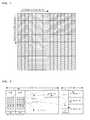
- FIG. 1 is a diagram illustrating a method of allocating resources along a time axis and a frequency axis in Orthogonal Frequency Division Multiple Access (OFDMA).
- OFDMA Orthogonal Frequency Division Multiple Access
- FIG. 2 is a diagram showing the MAP structure of a portable Internet system.
- a plurality of pieces of data using the same channel coding method and modulation method is sent in a batch in order to improve efficiency.
- a set of data regions using the same channel coding method and modulation method is referred to as a "burst."
- the location and size information of each burst can be seen from the MAP information of a frame, as shown in FIG. 2 .
- the term 'frame' refers to a structured data sequence having a fixed duration, which is used in the Physical Layer (PHY) standard.
- PHY Physical Layer
- a single frame may include both of a Downlink (hereinafter abbreviated as "DL”; a link from a Radio Access Station (RAS) to a PSS) sub-frame and an Uplink (hereinafter abbreviated as "UL”; a link from a PSS to an RAS) sub-frame.
- DL Downlink
- RAS Radio Access Station
- UL Uplink
- MAP information Since the portable Internet system employs Time Division Duplexing (TDD), in which UL transmission and DL transmission share the same frequency but are performed at different times, essential information, including the length of a single frame and the ratio of a DL section to a UL section, is provided via MAP information.
- an RAS may send different MAPs through each frame.
- a MAP may be divided into DL_MAP, containing DL transmission information, and UL_MAP, containing UL resource access authority.
- DL_MAP can be defined as a Media Access Control (MAC) layer message that defines the symbol offset and sub-channel offset of a burst divided and multiplexed along the subchannel and time axes on a downlink by an RAS, and the numbers of symbols and sub-channels, that is, allocated resources.
- MAC Media Access Control
- a preamble which is defined uniquely, is present in the first symbol of the DL subframe, and the preamble includes cell Identification (ID) information and segment information.
- the portable Internet system supports a handover function for preventing the connection of a PSS from being terminated in the case where a PSS moves from a wireless interface, provided by an RAS, to a wireless interface, provided by another RAS, as in a typical mobile communication system.
- the portable Internet standard provides for an article that conducts the test of whether a PSS effectively performs a handover.
- Handover is classified as break-before-make handover, in which service from a target base station (hereinafter simply abbreviated as a 'target BS') starts to be provided after connection with an existing serving base station (hereinafter simply abbreviated as a 'serving BS') has been released, or as make-before-break handover, in which service from a target BS starts to be provided before connection with an existing serving BS is released.
- the 'serving BS' is a base station with which a PSS has recently registered during initial network entry or handover
- the 'target BS' is a base station with which a PSS will register at the end of handover.
- an object of the present invention is to provide a portable Internet analyzer having a handover test function, which enables a handover test function to be effectively performed on a PSS using a single portable Internet analyzer, so that test equipment construction costs can be reduced and the establishment of UL and DL synchronization and integrated control can be very easily performed.
- the present invention provides a portable Internet analyzer having a handover test function, including a transmission unit for encoding various DownLink (DL) signals of a serving Base Station (BS) or/and a target BS using a preamble index, including a cell ID assigned in advance in a form of a unique code in association with a handover test, synthesizing the encoded signals, and sending the synthesized signals to a Portable Subscriber Station (PSS); a reception unit for receiving various UpLink (UL) signals from the PSS in association with the handover test, and decoding the UL signals using the cell Parameters of the serving BS or/and target BS; a switching unit for selectively switching the transmission unit and the reception unit to the PSS for each of DL and UL sections of each frame; and a central control unit for generating various Media Access Control (MAC) messages to be sent to the PSS through the transmission unit in association with the handover test, analyzing handover test-related MAC messages received through the reception unit, and
- DL DownLink
- the transmission unit may include a serving BS signal generation unit and target BS signal generation unit for implementing a physical layer algorithm, which includes encoding using the preamble indices and is performed in the serving BS and the target BS in association with the handover test, power/frequency adjustment units for separately adjusting power and frequency of the various DL signals output from the serving BS signal generation unit and the target BS signal generation unit, a mixer for mixing the DL signals output from respective power/frequency adjustment units, and a transmission control unit for implementing an algorithm of a MAC layer, which is a relatively upper layer, generating a MAC Protocol Data Unit (MAC PDU), generating an Uplink Channel Descriptor (UCD)/Downlink Channel Descriptor (DCD), including a UL cell ID, and other required messages, transferring the messages to the serving BS signal generation unit and the target BS signal generation unit, and controlling respective power/frequency adjustment units.
- MAC PDU MAC Protocol Data Unit
- UCD Uplink Channel Descriptor
- DCD Downlink Channel De
- the transmission unit may be further provided with a function of separately controlling Carrier to Interference Noise Ratios (CINRs) of various DL signals output from the serving BS signal generation unit and the target BS signal generation unit, or a function of separately controlling timing offsets between various DL signals output from the serving BS signal generation unit and the target BS signal generation unit.
- CINRs Carrier to Interference Noise Ratios
- serving BS signal generation unit and the target BS signal generation unit be implemented using Field Programmable Gate Arrays (FPGAs) or Digital Signal Processors (DSPs) and the transmission control unit be implemented using a DSP.
- FPGAs Field Programmable Gate Arrays
- DSPs Digital Signal Processors
- the reception unit may include a serving BS signal analysis unit and target BS signal analysis unit for receiving various types of UL signals from the PSS and decoding the received UL signals using cell Parameters assigned to the serving BS signal generation unit and the target BS signal generation unit, and a reception control unit for controlling operation of the serving BS signal analysis unit and the target BS signal analysis unit and transferring the signals, decoded by the serving BS signal analysis unit and the target BS signal analysis unit, to the central control unit.
- a serving BS signal analysis unit and target BS signal analysis unit for receiving various types of UL signals from the PSS and decoding the received UL signals using cell Parameters assigned to the serving BS signal generation unit and the target BS signal generation unit
- a reception control unit for controlling operation of the serving BS signal analysis unit and the target BS signal analysis unit and transferring the signals, decoded by the serving BS signal analysis unit and the target BS signal analysis unit, to the central control unit.
- the central control unit may be implemented using a typical personal computer, maintain synchronization between the transmission unit and the reception unit while bidirectionally communicating with the transmission control unit of the transmission unit and the reception control unit of the reception unit, perform a backbone function for the serving BS signal generation unit, the target BS signal generation unit, the serving BS signal analysis unit and the target BS signal analysis unit, generate messages to be sent through the transmission unit, generate UL-MAP information, transfer the UL-MAP information to the transmission unit and the reception unit, provides a user interface, which is configured to receive various handover test-related items set or input by a user, to the user, analyze the results of the decoding, received from the reception unit, and various types of data, received from the PSS, and notify the user of the results of the analysis.
- WiMAX system analyzer which is similar to Base Station Emulator(BSE), having a handover test function according to the present invention will be described in detail below with reference to the accompanying drawings.
- FIG. 3 is a diagram showing the network configuration of a typical portable Internet system.
- the basic network configuration of the portable Internet system includes Portable Subscriber Stations (PSSs), Radio Access Stations (RASs), and Access Control Routers (ACRs).
- PSSs Portable Subscriber Stations
- RASs Radio Access Stations
- ACRs Access Control Routers
- the PSSs perform the functions of portable Internet wireless access, IP-based service access, IP mobility, PSS/user authentication and security, the reception of multicast service, and interworking with other networks.
- the RASs perform the functions of portable Internet wireless access, wireless resource management and control, support for mobility handoff, authentication and security, the provision of QoS, downlink multicast, billing, the creation of statistical information, and the provision of notification.
- the ACRs perform the functions of IP routing, mobility management, authentication and security, QoS provision, IP multicasting, the provision of billing service provision to a billing server, mobility control between the RASs under each of the ACRs, and resource management and
- Table 1 shows principal parameters and essential requirements in the portable Internet system. As shown in Table 1, it can be seen that the portable Internet system, which is the object of analysis of the present invention, employs Time Division Duplexing (TDD) as a duplex operation method and OFDMA as a multiple access method.
- TDD Time Division Duplexing
- OFDMA OFDMA
- Table 1 Item Method or value duplexing method TDD multiple access method OFDMA system bandwidth 8.75 MHz transmission rate per subscriber uplink minimum/maximum 128 Kbps/1 Mbps downlink minimum/maximum 512 Kbps/3 Mbps frequency reuse coefficient 1 frequency efficiency maximum frequency efficiency: downlink/uplink (6/2) average frequency efficiency: downlink/uplink (2/1) handoff inter-cell handoff within RAS, inter-RAS handoff, inter-frequency handoff: 150 ms mobility maximum of 60 km/h service coverage pico-cell: 100 m micro-cell: 400 m macro-cell: 1 km
- Table 2 shows the basic parameters of OFDMA for a Partial Usage of Sub-Channel (PUSC) diversity sub-channel, which is designated as an essential implementation option in the portable Internet system.
- the length of a single TDD frame is 5 ms and symbol time is 115.2 ⁇ s.
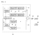
- FIG. 4 is a block diagram of a portable Internet analyzer 100 having a handover test function according to an embodiment of the present invention.
- the portable Internet analyzer 100 may include a transmission unit 110 for encoding various DL signals of a serving Base Station (BS) or/and a target BS using a preamble index, including a cell ID assigned in advance in the form of a unique code in association with a handover test, synthesizing the encoded signals, and sending the synthesized signals to a PSS, a reception unit 130 for receiving various UL signals (which will be described below) from the PSS 200 in association with the handover test and decoding the received UL signals using the cell Parameters of the serving BS or/and target BS, a switching unit 140 for selectively switching the transmission unit 110 and the reception unit 130 to the PSS 200 for each of the DL and UL sections of each frame, and a central control unit 120 for generating various types of MAC messages to be sent to
- BS Base Station
- a target BS
- the transmission unit 110 includes a serving BS signal generation unit 112 and target BS signal generation unit 113 for implementing a physical layer algorithm, which is performed in the serving BS and the target BS in association with a handover test, power/frequency adjustment units 114 and 115 for separately adjusting the power and frequency of various DL signals output from the serving BS signal generation unit 112 and the target BS signal generation unit 113, a mixer 116 for mixing DL signals output from respective power/frequency adjustment units 114 and 115, and a transmission control unit 111 for implementing the algorithm of a MAC layer, which is a relatively upper layer, generating a MAC Protocol Data Unit (MAC PDU), generating an Uplink Channel Descriptor (UCD)/Downlink Channel Descriptor (DCD), including a UL cell ID, and other required messages, transferring the messages to the serving BS signal generation unit 112 and the target BS signal generation unit 113, and controlling respective power/frequency adjustment units 114 and 115.
- MAC PDU MAC Protocol Data Unit
- the serving BS signal generation unit 112 and the target BS signal generation unit 113 chiefly perform simple tasks requiring very short processing times, and thus they may be implemented using Field Programmable Gate Arrays (FPGAs) or Digital Signal Processors (DSPs) that are suitable for such tasks.
- the transmission control unit 111 may be implemented using a DSP that is suitable for rapid operation.
- the reception unit 130 may include a serving BS signal analysis unit 132 and target BS signal analysis unit 133 for receiving various types of UL signals from the PSS 200 and decoding the received UL signals using cell Parameters assigned to the serving BS signal generation unit 112 and the target BS signal generation unit 113, and a reception control unit 131 for controlling the operation of the serving BS signal analysis unit 132 and the target BS signal analysis unit 133 and transferring the signals, decoded by the serving BS signal analysis unit 132 and the target BS signal analysis unit 133, to the central control unit 120.
- the serving BS signal analysis unit 132 and the target BS signal analysis unit 133 may be implemented using FPGAs or DSPs, while the reception control unit 131 may be implemented using a DSP.
- the central control unit 120 may be implemented using a typical personal computer.
- the central control unit 120 maintains synchronization between the transmission unit 110 and the reception unit 130 while bidirectionally communicating with the transmission control unit 111 of the transmission unit 110 and the reception control unit 131 of the reception unit 130, performs a backbone function for the serving BS signal generation unit 112, the target BS signal generation unit 113, the serving BS signal analysis unit 132 and the target BS signal analysis unit 133, generates messages to be sent through the transmission unit 110, generates UL-MAP information, and transfers the UL-MAP information to the transmission unit 110 and the reception unit 130.
- the central control unit 120 provides a user interface, which is configured to receive various handover test-related items set or input by a user, to the user, analyzes the decoding results, received from the reception unit 130, and various types of data, received from the PSS 200, and notifies the user of the results of the analysis.
- the central control unit 120 connects with the PSS 200 through the Diagnostic Monitoring (DM) port 220 of the PSS 200 via a wired connection.
- the switching unit 140 may be implemented using a typical electronic switch. The fixed contact of the switching unit 140 is connected to the PSS 200 through the RF Radio Frequency terminal 210, while the two movable contacts of the switching unit 140 are connected to the transmission unit 110 and the reception unit 130, respectively.
- the serving BS signal generation unit 112 and the target BS signal generation unit 113 are assigned two different preamble indices (cell IDs and segments) so as to distinguish them from each other, and the serving BS signal analysis unit 132 and the target BS signal analysis unit 133 decode received UL signals using the cell Parameters assigned to the serving BS signal generation unit 112 and the target BS signal generation unit 113.
- FIG. 5 is a call flow diagram showing a handover test procedure that is performed at the request of an RAS.
- the generation of DL signals in the serving BS sBS and the generation of DL signals in the target BS tBS may be respectively performed in the serving BS signal generation unit 112 of the portable Internet analyzer 100 and in the target BS signal generation unit 113 of the portable Internet analyzer 100, and the reception and decoding of UL signals in the serving BS sBS and the reception and decoding of UL signals in the target BS tBS may be respectively performed in the serving BS signal analysis unit 132 of the portable Internet analyzer 100 and in the target BS signal analysis unit 133 of the portable Internet analyzer 100.
- the backbone may be realized by the central control unit 120. As shown in FIG.
- the PSS scans adjacent BSs at predetermined intervals. This may be realized by receiving MOB_NBR_ADV messages that the serving BS sBS and the target BS tBS send to the PSS, which identifies a network and tries initial network entry or handover, at predetermined intervals of, for example, 30 seconds, in order to determine the characteristics of adjacent BSs (a target BS).
- the serving BS sBS exchanges handover-related messages with an adjacent BS that is specified in a MOB_BSHO-REQ message (which will be described later), that is, the target BS tBS, via backbone, determines a suitable recommended BS list (in this case, a target BS tBS) using its own algorithm, and sends the MOB_BSHO-REQ message to the PSS.
- a MOB_BSHO-REQ message includes the BS_ID of the target BS tBS and a preamble index Preamble Index.
- the PSS finally decides to perform handover and then notifies the serving BS sBS of the decision to perform handover by sending a MOB_HO-IND message, including a target BS-ID, to the serving BS sBS.
- a MOB_HO-IND message including a target BS-ID
- the PSS releases wireless connection with the serving BS sBS and attempts to reconnect with the target BS tBS.
- the serving BS sBS which has received the MOB_HO-IND message, notifies the target BS tBS, specified in the MOB HO-IND message, of the handover via the backbone.
- the PSS is assigned UL resources capable of sending an RNG-REQ message by the target BS tBS through code division multiple access code ranging.
- the target BS tBS having received the RNG-REQ message, acquires the context of the PSS and checks the authentication information of the PSS from the serving BS sBS, specified in the message, through the backbone.
- the target BS tBS having determined that the PSS in question is a normal PSS, assigns system resources to the PSS and then responds by sending the RNG-RSP message. Thereafter, the target BS tBS starts to send DL traffic to the PSS.
- FIG. 6 is a call flow showing a handover test procedure that is performed at the request of the PSS.
- the generation of DL signals in the serving BS sBS and the generation of DL signals in the target BS tBS may be respectively performed in the serving BS signal generation unit 112 of the portable Internet analyzer 100 and in the target BS signal generation unit 113 of the portable Internet analyzer 100, and the reception and decoding of UL signals in the serving BS sBS and the reception and decoding of UL signals in the target BS tBS may be respectively performed in the serving BS signal analysis unit 132 of the portable Internet analyzer 100 and in the target BS signal analysis unit 133 of the portable Internet analyzer 100.
- the backbone may be embodied by the central control unit 120.
- the PSS scans adjacent BSs at predetermined time intervals. This may be performed by receiving MOB_NBR_ADV messages sent by the serving BS sBS and the target BS tBS to the PSS, which identifies a network and looks for initial network entry and handover, at predetermined intervals of, for example, 30 seconds, in order to determine the characteristics of adjacent BSs (a target BS).
- MOB_NBR_ADV message may include a time/frequency synchronization identifier and a DCD/UCD reference identifier.
- the transmission control unit 111 enables the PSS to determine that a handover condition has been fulfilled by decreasing the intensity of the output signal of the serving BS signal generation unit 112 and increasing the intensity of the output signal of the target BS signal generation unit 113 through the power/frequency adjustment units 114 and 115.
- the PSS determines whether the handover condition has been met, and sends a MOB_MSHO-REQ message to the serving BS sBS if the handover condition has been met.
- Whether the handover condition has been met may be determined, for example, by comparing the intensity of a signal, received from the serving BS, with the intensity of a signal, received from the target BS. Accordingly, the central control unit 120 of the portable Internet analyzer 100 can appropriately adjust power, output from the serving BS signal generation unit 112 and the target BS signal generation unit 113, by controlling the power/frequency adjustment units 114 and 115 at this time.
- the serving BS sBS exchanges handover-related information with an adjacent BS, specified in the MOB_MSHO-REQ message, that is, a target BS tBS, via the backbone. Thereafter, the serving BS sBS determines a suitable recommended BS, that is, a target BS tBS, using its own algorithm, and responds to the PSS via a MOB_BSHO-RSP message.
- the PSS finally decides to perform handover and then notifies the serving BS sBS of the decision to perform handover by sending a MOB_HO-IND message, including a target BS-ID, to the serving BS sBS.
- the PSS releases wireless connection with the serving BS sBS and attempts to reconnect with the target BS tBS.
- the serving BS sBS that has received the MOB_HO-IND message notifies the target BS tBS, specified in the MOB_HO-IND message, of handover via the backbone. Thereafter, the PSS is assigned UL resources capable of transmitting an RNG-REQ message by the target BS tBS through Code Division Multiple Access Code Ranging.
- the target BS tBS having received the RNG-REQ message, acquires the context of the PSS and checks the authentication information of the PSS from the serving BS sBS, specified in the message, through the backbone.
- the target BS tBS having determined that the PSS in question is a normal PSS, assigns system resources to the PSS and then responds by sending the RNG-RSP message. Thereafter, the target BS tBS starts to send DL traffic to the PSS.
- the central control unit 120 checks and determines whether the PSS 200 appropriately performs operations required for the handover by analyzing various messages, received from the PSS 200 through the serving BS signal analysis unit 132 and the target BS signal analysis unit 133, and data, directly transferred by the PSS 200 through the DM port 220, at respective steps of the call flows shown in FIGS. 5 and 6 .
- the portable Internet analyzer having a handover test function is not limited to the above-described embodiments, but may be variously modified and then worked within the range of the technical spirit of the present invention.
- respective blocks of FIG. 4 have been determined from the point of view of functionality.
- functions of separately controlling Carrier to Interference Noise Ratio (CINR) or timing offset may be provided inside, in front of or behind the power/frequency adjustment units 114 and 115.
- CINR Carrier to Interference Noise Ratio
- the function of controlling CINR is a function of adding or subtracting a desired target noise signal to or from respective frames
- a function of controlling a timing offset is a function of providing a time lag between the DL signal of the serving BS and the DL signal of the target BS, and may be used to provide a time delay between the DL signal of the serving BS and the DL signal of the target BS.
- the signal analysis unit of the Portable Internet Analyzer decodes UL Signals using parameters such as DL Cell ID and UL Cell ID of Service Base Station and/or Target Base Station, and executes CRC check which leads to discriminate whether PSS transmits a signal to either Serving BS or Target. Further, the accuracy of the discrimination could be improved based upon the fact that Central Control Unit, controlling handover process, manages the status on transmitting UL signals to which base station.
- a handover test function can be effectively performed on a PSS using a single portable Internet analyzer, and thus the test equipment construction costs can be reduced and the establishment of UL and DL synchronization and integrated control can be very conveniently performed.
Landscapes
- Engineering & Computer Science (AREA)
- Computer Networks & Wireless Communication (AREA)
- Signal Processing (AREA)
- Mobile Radio Communication Systems (AREA)
Applications Claiming Priority (1)
| Application Number | Priority Date | Filing Date | Title |
|---|---|---|---|
| KR1020070008928A KR100790333B1 (ko) | 2007-01-29 | 2007-01-29 | 핸드오버 테스트기능을 갖는 휴대인터넷 계측기 |
Publications (4)
| Publication Number | Publication Date |
|---|---|
| EP1950990A2 true EP1950990A2 (fr) | 2008-07-30 |
| EP1950990A3 EP1950990A3 (fr) | 2015-11-04 |
| EP1950990B1 EP1950990B1 (fr) | 2017-10-11 |
| EP1950990B8 EP1950990B8 (fr) | 2017-11-15 |
Family
ID=39216223
Family Applications (1)
| Application Number | Title | Priority Date | Filing Date |
|---|---|---|---|
| EP08101055.5A Not-in-force EP1950990B8 (fr) | 2007-01-29 | 2008-01-29 | Analyseur internet portable doté d'une fonction de test de transfert |
Country Status (5)
| Country | Link |
|---|---|
| US (1) | US7869370B2 (fr) |
| EP (1) | EP1950990B8 (fr) |
| JP (1) | JP4601677B2 (fr) |
| KR (1) | KR100790333B1 (fr) |
| ES (1) | ES2655242T3 (fr) |
Cited By (2)
| Publication number | Priority date | Publication date | Assignee | Title |
|---|---|---|---|---|
| CN104661254A (zh) * | 2015-02-16 | 2015-05-27 | 北京电信技术发展产业协会 | Lte-a终端mac层载波聚合一致性测试方法和装置 |
| CN113228738A (zh) * | 2019-01-11 | 2021-08-06 | Lg 电子株式会社 | 用于在无线通信系统中执行移动性的方法和装置 |
Families Citing this family (4)
| Publication number | Priority date | Publication date | Assignee | Title |
|---|---|---|---|---|
| KR20070061407A (ko) * | 2005-12-08 | 2007-06-13 | 한국전자통신연구원 | 휴대인터넷 시스템의 핸드오버 재설정 방법 |
| ES2391366T3 (es) | 2008-05-07 | 2012-11-23 | Telefonaktiebolaget Lm Ericsson (Publ) | Métodos, sistemas y disposiciones de prueba para verificar la conformidad con especificaciones de requisitos |
| WO2010079532A1 (fr) * | 2009-01-07 | 2010-07-15 | 富士通株式会社 | Procédé de communication sans fil dans un système de communication sans fil, système de communication sans fil, station de base et station mobile |
| KR101657444B1 (ko) | 2015-05-13 | 2016-09-20 | 주식회사 이노와이어리스 | 모바일 핸드 오버 테스트 시스템 |
Family Cites Families (8)
| Publication number | Priority date | Publication date | Assignee | Title |
|---|---|---|---|---|
| JP3516663B2 (ja) * | 2001-02-26 | 2004-04-05 | 埼玉日本電気株式会社 | Cdma基地局試験装置及び基地局試験方法 |
| JP2002291011A (ja) * | 2001-03-23 | 2002-10-04 | Toshiba Corp | 無線装置及び無線装置のハンドオーバ制御方法 |
| KR100425990B1 (ko) * | 2001-05-30 | 2004-04-06 | 에스케이씨앤씨 주식회사 | 아이엠티2000 기지국 제어기 테스트 시스템 |
| JP2003143055A (ja) | 2001-11-01 | 2003-05-16 | Matsushita Electric Ind Co Ltd | 基地局シミュレータ |
| KR20050015119A (ko) * | 2003-08-04 | 2005-02-21 | 삼성전자주식회사 | 광대역 무선 접속 통신 시스템에서 레인징 신호 변조 장치및 방법 |
| US7190978B2 (en) * | 2004-07-02 | 2007-03-13 | Anritsu Corporation | Mobile network simulator apparatus |
| US8019333B2 (en) | 2005-03-14 | 2011-09-13 | Qualcomm Incorporated | Apparatus and methods for product acceptance testing on a wireless device |
| US20070002723A1 (en) * | 2005-06-09 | 2007-01-04 | Nokia Corporation | Signaling network ID in TPS bits |
-
2007
- 2007-01-29 KR KR1020070008928A patent/KR100790333B1/ko not_active Expired - Fee Related
-
2008
- 2008-01-28 US US12/020,763 patent/US7869370B2/en active Active
- 2008-01-29 JP JP2008017698A patent/JP4601677B2/ja not_active Expired - Fee Related
- 2008-01-29 EP EP08101055.5A patent/EP1950990B8/fr not_active Not-in-force
- 2008-01-29 ES ES08101055.5T patent/ES2655242T3/es active Active
Cited By (3)
| Publication number | Priority date | Publication date | Assignee | Title |
|---|---|---|---|---|
| CN104661254A (zh) * | 2015-02-16 | 2015-05-27 | 北京电信技术发展产业协会 | Lte-a终端mac层载波聚合一致性测试方法和装置 |
| CN113228738A (zh) * | 2019-01-11 | 2021-08-06 | Lg 电子株式会社 | 用于在无线通信系统中执行移动性的方法和装置 |
| CN113228738B (zh) * | 2019-01-11 | 2023-10-20 | Lg 电子株式会社 | 用于在无线通信系统中执行移动性的方法和装置 |
Also Published As
| Publication number | Publication date |
|---|---|
| EP1950990B1 (fr) | 2017-10-11 |
| JP2008187715A (ja) | 2008-08-14 |
| KR100790333B1 (ko) | 2008-01-02 |
| EP1950990B8 (fr) | 2017-11-15 |
| US7869370B2 (en) | 2011-01-11 |
| ES2655242T3 (es) | 2018-02-19 |
| EP1950990A3 (fr) | 2015-11-04 |
| JP4601677B2 (ja) | 2010-12-22 |
| US20080181120A1 (en) | 2008-07-31 |
Similar Documents
| Publication | Publication Date | Title |
|---|---|---|
| US12495338B2 (en) | Mobile communications network, communications device, infrastructure equipment and methods | |
| TWI475830B (zh) | 支援新版utran方法及系統 | |
| US8358624B1 (en) | Bidirectional uplink/downlink handoff | |
| US20080153497A1 (en) | Apparatus, system and method for managing wireless service to a wireless communication device | |
| JP2011520399A (ja) | システム間シグナリングを用いたWiMAXとCDMAとの間でのシステム間ハンドオーバ | |
| KR20070080556A (ko) | 무선 네트워크(network) 안에서 상향(uplink)및 하향(downlink) 대역폭(bandwidth)의선택 및 신호 방법 | |
| KR20100105488A (ko) | 측정 보고 방법 및 관련된 통신 기기 | |
| EP1950990B1 (fr) | Analyseur internet portable doté d'une fonction de test de transfert | |
| US20100182900A1 (en) | Apparatus and method for reusing base station identifier in a broadband wireless communication system | |
| KR20100113406A (ko) | 무선통신시스템에서 매크로 셀과 펨토 셀간 핸드오버 지원 장치 및 방법 | |
| WO2009108723A2 (fr) | Dispositif, système t procédé de gestion d'un service sans fil vers un dispositif de communication sans fil | |
| KR20050107253A (ko) | 이동 광대역 무선 접속 시스템에서 빠른 핸드오버를 위한효율적인 고속 레인징 지원 장치 및 방법 | |
| KR101012007B1 (ko) | 광대역 무선 통신시스템에서 인접 기지국 신호를스캐닝하기 위한 방법 및 장치 | |
| KR200428610Y1 (ko) | 발전된 지상 무선 접속 네트워크를 지원하는 시스템 | |
| HK1183194A (en) | Method and system for supporting an evolved utran | |
| HK1114964B (en) | Method and system for supporting an evolved utran |
Legal Events
| Date | Code | Title | Description |
|---|---|---|---|
| PUAI | Public reference made under article 153(3) epc to a published international application that has entered the european phase |
Free format text: ORIGINAL CODE: 0009012 |
|
| AK | Designated contracting states |
Kind code of ref document: A2 Designated state(s): AT BE BG CH CY CZ DE DK EE ES FI FR GB GR HR HU IE IS IT LI LT LU LV MC MT NL NO PL PT RO SE SI SK TR |
|
| AX | Request for extension of the european patent |
Extension state: AL BA MK RS |
|
| PUAL | Search report despatched |
Free format text: ORIGINAL CODE: 0009013 |
|
| AK | Designated contracting states |
Kind code of ref document: A3 Designated state(s): AT BE BG CH CY CZ DE DK EE ES FI FR GB GR HR HU IE IS IT LI LT LU LV MC MT NL NO PL PT RO SE SI SK TR |
|
| AX | Request for extension of the european patent |
Extension state: AL BA MK RS |
|
| RIC1 | Information provided on ipc code assigned before grant |
Ipc: H04Q 7/38 00000000ALI20150930BHEP Ipc: H04Q 7/34 00000000AFI20150930BHEP |
|
| 17P | Request for examination filed |
Effective date: 20160310 |
|
| RBV | Designated contracting states (corrected) |
Designated state(s): AT BE BG CH CY CZ DE DK EE ES FI FR GB GR HR HU IE IS IT LI LT LU LV MC MT NL NO PL PT RO SE SI SK TR |
|
| 17Q | First examination report despatched |
Effective date: 20160525 |
|
| AKX | Designation fees paid |
Designated state(s): AT BE BG CH CY CZ DE DK EE ES FI FR GB GR HR HU IE IS IT LI LT LU LV MC MT NL NO PL PT RO SE SI SK TR |
|
| AXX | Extension fees paid |
Extension state: MK Extension state: AL Extension state: BA Extension state: RS |
|
| REG | Reference to a national code |
Ref country code: DE Ref legal event code: R079 Ref document number: 602008052433 Country of ref document: DE Free format text: PREVIOUS MAIN CLASS: H04Q0007340000 Ipc: H04W0024080000 |
|
| RIC1 | Information provided on ipc code assigned before grant |
Ipc: H04W 36/00 20090101ALN20161209BHEP Ipc: H04W 24/08 20090101AFI20161209BHEP |
|
| GRAP | Despatch of communication of intention to grant a patent |
Free format text: ORIGINAL CODE: EPIDOSNIGR1 |
|
| INTG | Intention to grant announced |
Effective date: 20170426 |
|
| GRAS | Grant fee paid |
Free format text: ORIGINAL CODE: EPIDOSNIGR3 |
|
| GRAA | (expected) grant |
Free format text: ORIGINAL CODE: 0009210 |
|
| GRAT | Correction requested after decision to grant or after decision to maintain patent in amended form |
Free format text: ORIGINAL CODE: EPIDOSNCDEC |
|
| AK | Designated contracting states |
Kind code of ref document: B1 Designated state(s): AT BE BG CH CY CZ DE DK EE ES FI FR GB GR HR HU IE IS IT LI LT LU LV MC MT NL NO PL PT RO SE SI SK TR |
|
| REG | Reference to a national code |
Ref country code: GB Ref legal event code: FG4D |
|
| REG | Reference to a national code |
Ref country code: CH Ref legal event code: EP |
|
| RAP2 | Party data changed (patent owner data changed or rights of a patent transferred) |
Owner name: INNOWIRELESS CO., LTD. |
|
| REG | Reference to a national code |
Ref country code: IE Ref legal event code: FG4D |
|
| REG | Reference to a national code |
Ref country code: AT Ref legal event code: REF Ref document number: 937038 Country of ref document: AT Kind code of ref document: T Effective date: 20171115 |
|
| REG | Reference to a national code |
Ref country code: DE Ref legal event code: R096 Ref document number: 602008052433 Country of ref document: DE |
|
| REG | Reference to a national code |
Ref country code: NL Ref legal event code: MP Effective date: 20171011 |
|
| REG | Reference to a national code |
Ref country code: ES Ref legal event code: FG2A Ref document number: 2655242 Country of ref document: ES Kind code of ref document: T3 Effective date: 20180219 |
|
| REG | Reference to a national code |
Ref country code: LT Ref legal event code: MG4D |
|
| REG | Reference to a national code |
Ref country code: AT Ref legal event code: MK05 Ref document number: 937038 Country of ref document: AT Kind code of ref document: T Effective date: 20171011 |
|
| PG25 | Lapsed in a contracting state [announced via postgrant information from national office to epo] |
Ref country code: NL Free format text: LAPSE BECAUSE OF FAILURE TO SUBMIT A TRANSLATION OF THE DESCRIPTION OR TO PAY THE FEE WITHIN THE PRESCRIBED TIME-LIMIT Effective date: 20171011 |
|
| PG25 | Lapsed in a contracting state [announced via postgrant information from national office to epo] |
Ref country code: NO Free format text: LAPSE BECAUSE OF FAILURE TO SUBMIT A TRANSLATION OF THE DESCRIPTION OR TO PAY THE FEE WITHIN THE PRESCRIBED TIME-LIMIT Effective date: 20180111 Ref country code: SE Free format text: LAPSE BECAUSE OF FAILURE TO SUBMIT A TRANSLATION OF THE DESCRIPTION OR TO PAY THE FEE WITHIN THE PRESCRIBED TIME-LIMIT Effective date: 20171011 Ref country code: FI Free format text: LAPSE BECAUSE OF FAILURE TO SUBMIT A TRANSLATION OF THE DESCRIPTION OR TO PAY THE FEE WITHIN THE PRESCRIBED TIME-LIMIT Effective date: 20171011 Ref country code: LT Free format text: LAPSE BECAUSE OF FAILURE TO SUBMIT A TRANSLATION OF THE DESCRIPTION OR TO PAY THE FEE WITHIN THE PRESCRIBED TIME-LIMIT Effective date: 20171011 |
|
| PGFP | Annual fee paid to national office [announced via postgrant information from national office to epo] |
Ref country code: DE Payment date: 20180122 Year of fee payment: 11 Ref country code: ES Payment date: 20180227 Year of fee payment: 11 |
|
| PG25 | Lapsed in a contracting state [announced via postgrant information from national office to epo] |
Ref country code: BG Free format text: LAPSE BECAUSE OF FAILURE TO SUBMIT A TRANSLATION OF THE DESCRIPTION OR TO PAY THE FEE WITHIN THE PRESCRIBED TIME-LIMIT Effective date: 20180111 Ref country code: HR Free format text: LAPSE BECAUSE OF FAILURE TO SUBMIT A TRANSLATION OF THE DESCRIPTION OR TO PAY THE FEE WITHIN THE PRESCRIBED TIME-LIMIT Effective date: 20171011 Ref country code: IS Free format text: LAPSE BECAUSE OF FAILURE TO SUBMIT A TRANSLATION OF THE DESCRIPTION OR TO PAY THE FEE WITHIN THE PRESCRIBED TIME-LIMIT Effective date: 20180211 Ref country code: GR Free format text: LAPSE BECAUSE OF FAILURE TO SUBMIT A TRANSLATION OF THE DESCRIPTION OR TO PAY THE FEE WITHIN THE PRESCRIBED TIME-LIMIT Effective date: 20180112 Ref country code: AT Free format text: LAPSE BECAUSE OF FAILURE TO SUBMIT A TRANSLATION OF THE DESCRIPTION OR TO PAY THE FEE WITHIN THE PRESCRIBED TIME-LIMIT Effective date: 20171011 Ref country code: LV Free format text: LAPSE BECAUSE OF FAILURE TO SUBMIT A TRANSLATION OF THE DESCRIPTION OR TO PAY THE FEE WITHIN THE PRESCRIBED TIME-LIMIT Effective date: 20171011 |
|
| REG | Reference to a national code |
Ref country code: DE Ref legal event code: R097 Ref document number: 602008052433 Country of ref document: DE |
|
| PG25 | Lapsed in a contracting state [announced via postgrant information from national office to epo] |
Ref country code: CZ Free format text: LAPSE BECAUSE OF FAILURE TO SUBMIT A TRANSLATION OF THE DESCRIPTION OR TO PAY THE FEE WITHIN THE PRESCRIBED TIME-LIMIT Effective date: 20171011 Ref country code: SK Free format text: LAPSE BECAUSE OF FAILURE TO SUBMIT A TRANSLATION OF THE DESCRIPTION OR TO PAY THE FEE WITHIN THE PRESCRIBED TIME-LIMIT Effective date: 20171011 Ref country code: DK Free format text: LAPSE BECAUSE OF FAILURE TO SUBMIT A TRANSLATION OF THE DESCRIPTION OR TO PAY THE FEE WITHIN THE PRESCRIBED TIME-LIMIT Effective date: 20171011 Ref country code: EE Free format text: LAPSE BECAUSE OF FAILURE TO SUBMIT A TRANSLATION OF THE DESCRIPTION OR TO PAY THE FEE WITHIN THE PRESCRIBED TIME-LIMIT Effective date: 20171011 |
|
| PLBE | No opposition filed within time limit |
Free format text: ORIGINAL CODE: 0009261 |
|
| STAA | Information on the status of an ep patent application or granted ep patent |
Free format text: STATUS: NO OPPOSITION FILED WITHIN TIME LIMIT |
|
| PG25 | Lapsed in a contracting state [announced via postgrant information from national office to epo] |
Ref country code: RO Free format text: LAPSE BECAUSE OF FAILURE TO SUBMIT A TRANSLATION OF THE DESCRIPTION OR TO PAY THE FEE WITHIN THE PRESCRIBED TIME-LIMIT Effective date: 20171011 Ref country code: PL Free format text: LAPSE BECAUSE OF FAILURE TO SUBMIT A TRANSLATION OF THE DESCRIPTION OR TO PAY THE FEE WITHIN THE PRESCRIBED TIME-LIMIT Effective date: 20171011 Ref country code: IT Free format text: LAPSE BECAUSE OF FAILURE TO SUBMIT A TRANSLATION OF THE DESCRIPTION OR TO PAY THE FEE WITHIN THE PRESCRIBED TIME-LIMIT Effective date: 20171011 |
|
| REG | Reference to a national code |
Ref country code: CH Ref legal event code: PL |
|
| 26N | No opposition filed |
Effective date: 20180712 |
|
| GBPC | Gb: european patent ceased through non-payment of renewal fee |
Effective date: 20180129 |
|
| PG25 | Lapsed in a contracting state [announced via postgrant information from national office to epo] |
Ref country code: LU Free format text: LAPSE BECAUSE OF NON-PAYMENT OF DUE FEES Effective date: 20180129 Ref country code: FR Free format text: LAPSE BECAUSE OF NON-PAYMENT OF DUE FEES Effective date: 20180131 |
|
| REG | Reference to a national code |
Ref country code: IE Ref legal event code: MM4A |
|
| REG | Reference to a national code |
Ref country code: FR Ref legal event code: ST Effective date: 20180928 |
|
| REG | Reference to a national code |
Ref country code: BE Ref legal event code: MM Effective date: 20180131 |
|
| PG25 | Lapsed in a contracting state [announced via postgrant information from national office to epo] |
Ref country code: CH Free format text: LAPSE BECAUSE OF NON-PAYMENT OF DUE FEES Effective date: 20180131 Ref country code: BE Free format text: LAPSE BECAUSE OF NON-PAYMENT OF DUE FEES Effective date: 20180131 Ref country code: LI Free format text: LAPSE BECAUSE OF NON-PAYMENT OF DUE FEES Effective date: 20180131 Ref country code: SI Free format text: LAPSE BECAUSE OF FAILURE TO SUBMIT A TRANSLATION OF THE DESCRIPTION OR TO PAY THE FEE WITHIN THE PRESCRIBED TIME-LIMIT Effective date: 20171011 Ref country code: GB Free format text: LAPSE BECAUSE OF NON-PAYMENT OF DUE FEES Effective date: 20180129 |
|
| PG25 | Lapsed in a contracting state [announced via postgrant information from national office to epo] |
Ref country code: IE Free format text: LAPSE BECAUSE OF NON-PAYMENT OF DUE FEES Effective date: 20180129 |
|
| PG25 | Lapsed in a contracting state [announced via postgrant information from national office to epo] |
Ref country code: MC Free format text: LAPSE BECAUSE OF FAILURE TO SUBMIT A TRANSLATION OF THE DESCRIPTION OR TO PAY THE FEE WITHIN THE PRESCRIBED TIME-LIMIT Effective date: 20171011 |
|
| REG | Reference to a national code |
Ref country code: DE Ref legal event code: R119 Ref document number: 602008052433 Country of ref document: DE |
|
| PG25 | Lapsed in a contracting state [announced via postgrant information from national office to epo] |
Ref country code: DE Free format text: LAPSE BECAUSE OF NON-PAYMENT OF DUE FEES Effective date: 20190801 |
|
| PG25 | Lapsed in a contracting state [announced via postgrant information from national office to epo] |
Ref country code: MT Free format text: LAPSE BECAUSE OF NON-PAYMENT OF DUE FEES Effective date: 20180129 |
|
| REG | Reference to a national code |
Ref country code: ES Ref legal event code: FD2A Effective date: 20200310 |
|
| PG25 | Lapsed in a contracting state [announced via postgrant information from national office to epo] |
Ref country code: TR Free format text: LAPSE BECAUSE OF FAILURE TO SUBMIT A TRANSLATION OF THE DESCRIPTION OR TO PAY THE FEE WITHIN THE PRESCRIBED TIME-LIMIT Effective date: 20171011 |
|
| PG25 | Lapsed in a contracting state [announced via postgrant information from national office to epo] |
Ref country code: ES Free format text: LAPSE BECAUSE OF NON-PAYMENT OF DUE FEES Effective date: 20190130 |
|
| PG25 | Lapsed in a contracting state [announced via postgrant information from national office to epo] |
Ref country code: PT Free format text: LAPSE BECAUSE OF FAILURE TO SUBMIT A TRANSLATION OF THE DESCRIPTION OR TO PAY THE FEE WITHIN THE PRESCRIBED TIME-LIMIT Effective date: 20171011 Ref country code: HU Free format text: LAPSE BECAUSE OF FAILURE TO SUBMIT A TRANSLATION OF THE DESCRIPTION OR TO PAY THE FEE WITHIN THE PRESCRIBED TIME-LIMIT; INVALID AB INITIO Effective date: 20080129 |
|
| PG25 | Lapsed in a contracting state [announced via postgrant information from national office to epo] |
Ref country code: CY Free format text: LAPSE BECAUSE OF FAILURE TO SUBMIT A TRANSLATION OF THE DESCRIPTION OR TO PAY THE FEE WITHIN THE PRESCRIBED TIME-LIMIT Effective date: 20171011 |