EP1951973B1 - Appareil pour la liaison d'objets - Google Patents
Appareil pour la liaison d'objets Download PDFInfo
- Publication number
- EP1951973B1 EP1951973B1 EP06794700.2A EP06794700A EP1951973B1 EP 1951973 B1 EP1951973 B1 EP 1951973B1 EP 06794700 A EP06794700 A EP 06794700A EP 1951973 B1 EP1951973 B1 EP 1951973B1
- Authority
- EP
- European Patent Office
- Prior art keywords
- wire
- head
- twisting
- loop
- gripping
- Prior art date
- Legal status (The legal status is an assumption and is not a legal conclusion. Google has not performed a legal analysis and makes no representation as to the accuracy of the status listed.)
- Active
Links
Images






Classifications
-
- E—FIXED CONSTRUCTIONS
- E04—BUILDING
- E04G—SCAFFOLDING; FORMS; SHUTTERING; BUILDING IMPLEMENTS OR AIDS, OR THEIR USE; HANDLING BUILDING MATERIALS ON THE SITE; REPAIRING, BREAKING-UP OR OTHER WORK ON EXISTING BUILDINGS
- E04G21/00—Preparing, conveying, or working-up building materials or building elements in situ; Other devices or measures for constructional work
- E04G21/12—Mounting of reinforcing inserts; Prestressing
-
- E—FIXED CONSTRUCTIONS
- E04—BUILDING
- E04G—SCAFFOLDING; FORMS; SHUTTERING; BUILDING IMPLEMENTS OR AIDS, OR THEIR USE; HANDLING BUILDING MATERIALS ON THE SITE; REPAIRING, BREAKING-UP OR OTHER WORK ON EXISTING BUILDINGS
- E04G21/00—Preparing, conveying, or working-up building materials or building elements in situ; Other devices or measures for constructional work
- E04G21/12—Mounting of reinforcing inserts; Prestressing
- E04G21/122—Machines for joining reinforcing bars
- E04G21/123—Wire twisting tools
-
- B—PERFORMING OPERATIONS; TRANSPORTING
- B65—CONVEYING; PACKING; STORING; HANDLING THIN OR FILAMENTARY MATERIAL
- B65B—MACHINES, APPARATUS OR DEVICES FOR, OR METHODS OF, PACKAGING ARTICLES OR MATERIALS; UNPACKING
- B65B13/00—Bundling articles
- B65B13/18—Details of, or auxiliary devices used in, bundling machines or bundling tools
- B65B13/24—Securing ends of binding material
- B65B13/28—Securing ends of binding material by twisting
- B65B13/285—Hand tools
-
- E—FIXED CONSTRUCTIONS
- E04—BUILDING
- E04G—SCAFFOLDING; FORMS; SHUTTERING; BUILDING IMPLEMENTS OR AIDS, OR THEIR USE; HANDLING BUILDING MATERIALS ON THE SITE; REPAIRING, BREAKING-UP OR OTHER WORK ON EXISTING BUILDINGS
- E04G21/00—Preparing, conveying, or working-up building materials or building elements in situ; Other devices or measures for constructional work
- E04G21/12—Mounting of reinforcing inserts; Prestressing
- E04G21/122—Machines for joining reinforcing bars
Definitions
- This invention relates to apparatus and methods for binding together objects using wire to tie them to each other. It relates particularly, although not exclusively, to binding together reinforcing bars which provide reinforcement to concrete structures.
- reinforcing bars When building large concrete structures e.g. walls, floors, columns etc. in buildings, grids of reinforcing bars must typically be laid out and bound together on site before the concrete is poured over them.
- the reinforcing bars are laid out in a rectangular grid of horizontal and vertical bars. At selected intersections between horizontal and vertical bars, they are tied together using a loop of stiff wire which is passed diagonally under the intersection and the two ends of which are twisted together above the intersection in order to tie the two bars together.
- this has been carried out manually although it is difficult, laborious and repetitive.
- EP-A-1415917 , DE-A-19806995 and WO93/02816 disclose known machines for binding together reinforcing bars by tying wire around them.
- the invention provides an apparatus for tying a wire around one or more objects comprising means for passing said wire in a loop around the objects and means for twisting the ends of said loop together, said twisting means comprising at least one gripping means for gripping the wire, said gripping means being adapted to provide a variable gripping force so as to apply a predetermined tension to the wire during at least a first phase of twisting.
- the amount of grip is controlled to ensure that a desired amount of tension is applied to the wire during twisting. This helps to overcome the problems encountered in use of prior art devices in which the amount of grip could be influenced by uncontrolled external factors.
- the gripping means comprises one or more variable force clutch mechanisms.
- the apparatus comprises means for providing feedback of the amount of tension in the wire. This could, for example, be measured by monitoring current through a motor driving twisting means.
- the or each clutch mechanism comprises a member resiliently biased onto the wire and shaped to increase the clamping force on the wire as the wire is drawn past it.
- the tension applied could be substantially constant throughout the twisting or could be varied, e.g. to reduce it after the first one or few turns.
- the Applicant has recognised that the most effective binding turns are the first one or two and therefore that a much lower tension may be used for subsequent turns without affecting the binding tightness. After the first few turns it has been recognised that subsequent twisting essentially simply tidies up the ends of the wire.
- the arrangements set out above are an improvement on the arrangement in WO 2004/083559 where the degree of grip was not controlled. However, they share the principle of the wire being drawn out from the twisting mechanism by overcoming a resistance.
- the ends of the wire are gripped sufficiently tightly to prevent the ends of the wire being pulled out during twisting but wherein the twisting mechanism is arranged to be drawn towards the object(s) being tied against a resilient bias force during twisting.
- said resilient biasing force is provided by a sprung housing, stand or frame which engages the object(s) being tied.
- the compressible portion of the apparatus may be provided elsewhere, e.g. between a frame or housing and the parts of the apparatus mounting the twisting mechanism.
- the apparatus comprises wire issuing and wire receiving means arranged to pass a wire imparted with an arcuate set in a loop around the objects from the issuing means to the receiving means.
- the apparatus rather than the wire being guided around the objects to be tied with a pair of jaws, the apparatus relies on an arcuate set imparted to the wire to guide it around the objects to the receiving means. This is clearly advantageous as the alignment of the wire does not rely on the positions of jaws. The apparatus can therefore be made less prone to damage that prevents it working properly.
- the apparatus in accordance with the invention could be jaw-less.
- jaw-less is meant that no part of it will project below the lowermost member being tied and indeed no part of it need project below either or any of the members to be tied together, so the whole operation can be carried out from above.
- the apparatus can be made extremely robustly. However it is not essential for it to be jaw-less.
- the Applicant has found that in some situations it is necessary or desirable to increase the force transmitted from the wire issuing means through the wire, for example to overcame resistance at the receiving means.
- wire containment means are provided for restricting the growth in diameter of the wire loop. Such means allow a significantly greater force to be transmitted through the wire loop and thus make it easier to overcome any resistance encountered, e.g. at the receiving means.
- the wire containment means could simply be an extension of the shroud on one or both sides, a frame, or any other suitable structure for restricting enlargement of the loop.
- the wire containment means could even comprise one or more jaws. It will be appreciated however that in this example the jaw(s) are not relied upon to guide the wire accurately to the receiving means, the arcuate set achieves that, but rather to restrict enlargement of the loop. The construction of the jaw(s) may therefore be much simpler and the accurate positioning thereof is not essential in order to guide the wire. The benefits discussed above therefore still apply.
- the arcuate set which is imparted to the wire could simply be that which results from it being coiled around a spool for storage. However, this is possibly unreliable as spools may be of different sizes, wound to different tensions or unevenly; and the diameter of the set will reduce as the spool is consumed.
- the apparatus comprises means for imparting the required arcuate set. This could comprise, for example, pinch rollers and/or a suitably curved guide surface or channel.
- the set applied to the wire is preferably substantially planar so that the free end of the wire tends to return towards the point from which it was issued; although in preferred embodiments the wire receiving means is arranged to guide the free end of the wire so as to have a slight lateral offset. This means that the issuing and receiving means may be laterally offset from one another which allows the device as a whole to be kept as compact as possible.
- the wire receiving means preferably comprises a funnelled surface to guide the free end of the wire into means for gripping it.
- the range over which the free end of the wire may strike the receiving means and still be properly guided to the gripping means will of course depend on the accuracy with which the wire loop is guided through the air by its pre-given set.
- the receiving surface is adapted to accommodate the free end of the wire landing within 10 cm of the gripping means in any direction, more preferably within 5 cm and more preferably within 1 cm.
- the wire receiving means is adapted to detect when the free end of the wire has been received.
- the apparatus comprises means for determining if the wire has not been received correctly by the receiving means. For example such a determination could be made if the receiving means has not received the wire after a predetermined time; or after a predetermined number of revolutions of a feed mechanism; or any combination of these.
- the apparatus is configured to stop the wire feed if such a determination is made.
- it is also configured to release the wire as failure for the wire to be received normally indicates that it has become jammed or fouled. This could include cutting the wire to facilitate its removal.
- the apparatus comprises means for sensing the presence of a legitimate object to be tied in the zone through which the wire will pass. This enhances the safety of the apparatus by helping to ensure that the tying is only commenced in the correct circumstances.
- the sensing means could issue an alert if an appropriate object is not in the correct vicinity but preferably it simply prevents the tying action being initiated through a suitable controller.
- the sensing means could be configured to sense particular sizes or shapes corresponding to legitimate objects to be tied but preferably it senses the presence of an appropriate material for the object.
- the objects to be tied will be metal, more specifically steel.
- the sensing means is arranged to sense the presence of metal, e.g. steel objects.
- the sensing means is arranged to sense the thermal, or preferably electrical, conductivity of the object.
- the sensing means is arranged to sense the presence of a material having a degree of ferromagnetism such as a steel bar. Any suitable magnetic sensor may be employed but preferably the sensing means in such embodiments comprises a Hall effect device. Detecting the presence of an object having the correct properties is advantageous insofar as it can discriminate a metal bar from e.g. a finger which simple contact sensors (e.g. micro-switches) cannot.
- variable force gripping means may be sufficient to accommodate the normally encountered range of friction coefficients.
- conditioning means are provided for altering the frictional properties of the surface of the wire.
- the conditioning means could be arranged to reduce the friction presented by the wire - e.g. by smoothing, cleaning and/or lubricating the wire.
- the conditioning means is arranged to increase the friction of the surface. This could be done by e.g. by coating the wire with a suitable material but preferably it is done by altering the texture of the surface - i.e. roughening it.
- the conditioning means comprises means for serrating the surface.
- the conditioning means comprises a suitable set of rollers, one or more of which have a surface adapted to impart the desired texture.
- the conditioning means could be independent of other mechanisms in the apparatus.
- the conditioning means comprises a feed and/or bending roller which also performs another function in the operation of the apparatus.
- the surface conditioning could be applied around the whole circumference but in some preferred embodiments it is applied to part of the circumference only. This would allow it to be effective in some parts of the machine but not others depending on their circumferential orientation relative to the wire. Of course different conditioning could be applied to different parts of the circumference.
- the wire it is normally necessary for the wire to be cut from a spool before twisting commences.
- This could be effected by a dedicated cutter.
- the apparatus is configured to shear the wire as the twisting mechanism begins to turn. This is simpler and cheaper to manufacture than a dedicated cutter and associated controlling electronics. In some embodiments it could be arranged that more current is supplied to a motor at start-up to facilitate this.
- the Applicant has recognised the difficulties associated with dealing with the sharp ends that remain after the wire has been twisted.
- embodiments of the invention can be made much more robust than prior art machines and so will withstand better being used to knock over the wire after twisting.
- the apparatus comprises a guiding surface arranged to deflect the wire as it is being twisted so that the ends of the wire finish pointing at least partially in the direction of the objects being tied, i.e. downwardly where the apparatus is used in the normal configuration vertically, above the objects. It has been found that in accordance with this feature there is no need to knock over the twisted potion of wire in order satisfactorily to reduce the risk of snagging - having the ends of the wire pointing downwardly can be sufficient for this.
- the guiding surface is preferably formed as a depression on part of the twisting means.
- the surface is therefore preferably rotationally symmetric and smoothly rounded to prevent catching.
- the guiding surface is part-spherical.
- At least preferred embodiments of the apparatus of the invention comprise a rotatable head arranged to rotate in order to twist the ends of the wire together. It could be arranged that the rotatable head comprises the guide guides the wire to its maximum diameter - i.e. that which is necessary to form a loop which passes around the intersecting reinforcing bars. Such an arrangement might be constructionally simple. However the Applicant has realised that the resulting diameter of the rotating head and hence the overall size of the lower part of the apparatus can be undesirably large in this case. In fact it has appreciated that because in accordance with preferred embodiments the ends of the wire are drawn together prior to rotation, the diameter of the head need only accommodate this smaller separation.
- the rotatable head is smaller in diameter than the initial loop diameter.
- the wire issuing means is provided on the rotatable head this means that the wire will move from he point at which it issues from the head as it is drawn in.
- a slot is provided on the head to facilitate this.
- parking means are provided for returning the head to a predetermined 'parking' position or one of a plurality of predetermined parking positions. This is valuable as it ensures that the head is in the correct place for the next tying operation.
- the parking means is arranged to prevent the head from moving from said parking position in at least one direction.
- the parking means could comprise indexing or other position-determining means arranged to determine when the head is in a or the parking position so as to stop the motor and possibly engage a lock.
- a solenoid-operated latch or pin could be employed.
- the parking means referred to above comprises a ratchet arrangement arranged to prevent rotation of the head in one direction beyond one or more predetermined points.
- the ratchet arrangement comprises a resiliently biased pawl acting on the head.
- the head could for example be provided with a suitable notch, stop or detent.
- the pawl and ratchet surface could be reversed.
- Such ratchet arrangements are simple and reliable to implement and provide an automatic, physical, locking location of the head in a or the parking position when the head is rotated in the opposite direction to the normal twisting direction, in order to park it.
- the wire is cut where it crosses from the stationary part of the apparatus into the rotatable head in order to allow the head to rotate.
- a fresh length of wire is fed into the rotatable head when the next tying operation is commenced.
- This sequence is perfectly logical.
- the apparatus is arranged to pre-feed a length of wire beyond the cutting means at the end of a tying operation. By pre-feeding the wire at the end of the cutting operation, the subsequent tying operation can be carried out more quickly.
- this feature utilises the 'dead time' between tying operations which is required for the operator to move the machine to the next intersection requiring a tie. It has been found that in one example this can reduce the time for each tying operation by about 10 to 20 percent which is significant, particularly when multiplied across large numbers of operations.
- the amount of wire that is pre-fed will depend to an extent on the construction of the apparatus. It is normally expected however that the wire will be pre-fed to an extent that it is not exposed from the apparatus. Of course it is necessary to ensure that the pre-fed wire does not interfere with locating the apparatus at the next reinforcing bar intersection.
- the precise point in the cycle at which the pre-feed occurs is not critical as long as it happens at some stage between completion of one tying operation and commencement of the next. Preferably it occurs after the or a rotatable head has been locked to prevent rotation.
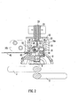
- FIGs. 1a , 1b and 2 there is shown two perspective views and a sectional view of part of an apparatus in accordance with the invention with certain parts such as the housing, handle, battery, controls, lower shroud and wire spool removed for clarity.
- the apparatus is shown situated over a junction where two steel bars 2 cross over each other at right angles.
- the steel bars 2 are intended to form a rectangular grid to be embedded in a concrete structure in order to reinforce it.
- a domed shroud is provided around the lower end of the apparatus and has two part-circular depressions so that the apparatus can securely rest on the upper of the two bars 2 without slipping off.
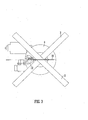
- the rotary head of the apparatus 4 This includes a horizontal circular base plate 6 extending up from which is a channel 8 which is approximately semi-circular in vertical section and of approximately constant width in the orthogonal direction. In the centre of base plate 6 is a part-spherical depression 9. The underneath of the base plate 6 is shown in Fig. 3 from which it will be seen that on one side there is a narrow slot 10 corresponding to one end of the semi-circular channel and on the other side of the plate 6 corresponding to the other end of the channel is a funnel region 12.
- the upper cylindrical portion of the head 14 which is rotatably mounted in the cylindrical portion 16a of a bracket member mounted to the housing (not shown) by a flange portion 16b (omitted from Fig. 1b ).
- the upper head portion is supported by two rotary bearings 18.
- a toothed gear wheel, 20 is provided fixed at the top of the head to allow it to be driven by a motor 22 via a worm gear.
- a solenoid assembly comprising a cylindrical outer tube 26 housing the coil and an inner plunger 28 which is able to slide vertically relative to the coil 26.
- an actuating disc 30 At the bottom end of the plunger 28 is an actuating disc 30, the purpose of which will be explained later.
- a pivotally mounted angled clutch lever 32 On the left hand side as seen from Fig. 2 , there may be seen a pivotally mounted angled clutch lever 32.
- a pair of compression springs 36 act on the longer, upper arm of the lever 32 so as to bias the lever in an anti-clockwise direction in which the shorter, lower arm is pressed downwardly.
- any number of springs might be used.
- To the right of the clutch lever 32 are a series of roller wheels 38a,38b,38c the purpose of which will be explained below.
- a similar clutch lever is provided displaced approximately 180 degrees around the head. This is not therefore visible in the sectional view.
- a wire feed inlet guide 40 which receives the free end of wire 46 which has been unwound from the spool (not shown).
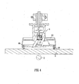
- FIG 4 is a partly-schematic view of the apparatus in which the lower shroud 42 is shown. At two opposed points just inside the edge of the shroud 42 are disposed a pair of Hall effect sensors 44 which protrude slightly from the shroud. However they could equally be flush or slightly recessed. A further two sensors are provided at 90 degrees to those shown so that whichever of the four possible rotational positions the apparatus is brought down onto a steel reinforcing bar 2, two of the Hall sensors will give a detectable electronic signal indicating the ferromagnetic nature of the steel.
- a pair of electrodes are arranged to contact the reinforcing bar when it is properly positioned, thereby completing an electrical circuit through the bar.
- the apparatus is first brought down onto the uppermost of a pair of steel reinforcing bars 2 which are crossed at right angles.
- the shroud 42 When the shroud 42 is properly resting on the bar 2, the presence of the steel will be sensed by the two Hall effect sensors 44 which will allow the tying operation to be commenced. If the operator should attempt to commence the tying operation before both Hall effect sensors 44 sense the presence of the steel bar 2, a warning light such as an LED is illuminated and further operation of the apparatus is prevented.
- the sensing is carried out by detecting the completion of an electrical circuit though the bar. This shares the advantage that the sensing mechanism cannot be fooled by part of an operator's body such as a finger, or clothing etc.
- the operator may commence the tying operation.
- the first part of this operation is to energise the solenoid coil 26 which pushes the plunger member 28 downwardly.
- This causes the actuating member 30 at the end of the plunger to be pressed downwardly onto the upper arms of the clutch levers 32 to press them down against the respective compression springs 36 and therefore raise the shorter, lower arms. This is the position which is shown in Figure 2 .
- the main motor 22 is, if necessary, operated just long enough to rotate head 4 via the worm drive and gear wheel 24, 20 so that a channel for receiving the wire 46 is in correct alignment with the wire feed inlet guide 40. This is called the "park" position.
- the correct alignment may be detected simply by respective contacts provided on upper head portion 14 and the cylindrical housing 16a or wire inlet guide 40, although of course there are many other possibilities for this position detection.
- a separate motor (not shown) is operated to drive a wire feed roller (also not shown) that acts on the wire 46 to feed it from the spool through the wire inlet guide 40 and into the aligned channel in the upper head portion 14.
- the wire is fed in horizontally and encounters the first of the passive rollers 38a.
- the first roller 38a causes the wire to bend downwardly slightly so that it passes between the second and third rollers 38b, 38c.
- the relative positions of the three passive rollers 38a,38b,38c is such that when the wire 46 emerges from them it is bent so as to have an arcuate set.
- the wire 46 continues to be driven by the wire feed roller, it encounters and is guided by the inner surface of the semi-circular channel 8.
- the free end of the wire re-enters the semi-circular channel 8, it encounters the second clutch lever. This can be detected by sensing a slight displacement of the lever or by a separate sensor such as a micro switch, Hall effect sensor or other position detection means.
- the motor feeding the wire is stopped and therefore the wire does not advance any further.
- the solenoid coil 26 is then de-energised which causes the plunger 28 to be retracted by a spring (not shown) which releases the two clutch levers 32 so that their respective compression springs 36 act to press their lower arms against the two ends of the wire loop and therefore hold the wire 46 in place.
- the wire feed motor is driven in reverse in order to apply tension to the wire loop which draws the wire in around the reinforcing bars 2.
- This may be seen in Figure 6a .
- Figure 6b shows detail of the clutch lever 32 on the feed side clamping the end of the wire 46.
- a similar arrangement clamps the other end of the wire as explained above.
- the torque supplied by the motor 22 is sufficient to shear the wire at the point where it crosses from the inlet guide 40 to the upper head portion 14 without the need for it to be cut.
- an initial surge current e.g. boosted by a charge stored in a capacitor
- the head 4 begins to twist the sides of the loop together above the reinforcing bars 2.
- the first one or two turns of the head are the most important in ensuring a tight binding. As will be appreciated, these initial twists are carried out under tension and therefore a very tight binding is achieved. As twisting continues, each successive turn is less important for providing a tight binding. As twisting continues the tension in the wire will increase. However, the shape of the rounded ends 32a of the clutch levers that bear against the ends of the wire mean that as the wire is pulled passed it, it will tend to be pulled slightly anti-clockwise (looking at the lever shown in Fig. 6a ) and so increase the friction on the wire. This arrangement acts as an effective self-regulating mechanism to ensure that the wire can be drawn out by a measured amount. Since the area of mutual contact between the clutch lever 32 and the wire 46 is relatively small, effectively a point contact, the resistance force is less dependent on the co-efficient of friction than in prior art arrangements.
- the apparatus determines that a malfunction has taken place and so stops the wire feed motor and then carries out the wire cutting operation described above by applying a surge current to the main motor 22.
- the head 4 is returned to the "park" position and a further solenoid is energised to project a pin from the cylindrical bracket housing 16a into the upper head portion 14 to prevent further rotation until the fault has been rectified and this rotation lock has been manually reset by a user.
- a warning signal is given to a user e.g. by illuminating a red LED.
- the main solenoid 26 is de-activated again.
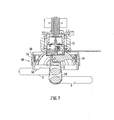
- FIG. 7 A second embodiment of the invention is shown in Figure 7 .
- the apparatus is broadly the same as the previously described embodiment except that it has a different lower shroud 48.
- the shroud 48 comprises a fixed portion 50 and a moveable sprung portion 52 mounted to the fixed portion by a series of circumferentially spaced compression springs 54.
- the lower sprung portion of the shroud 52 sits on the steel reinforcing bar 2 in use of the device.
- the combined force of the compression springs 54 is sufficient to bear not only the weight of the apparatus, but the initial tension applied to the wire 46 before twisting is commenced which is the stage depicted in Fig. 7 .
- FIG. 8 A further embodiment is shown in Fig. 8 .
- a set of rollers 138 impart an arcuate set to the wire 146 as it leaves the head.
- Wire containment means in the form of a pair of curved support members 160 extend down from a shroud 142 around the head so as to straddle the junction between the two bars being tied (not shown).
- the wire 146 advances around towards the receiving means it is guided by its arcuate set and does not even touch the support members 160.
- the end of the wire 146 encounters resistance at the receiving means, rather than advancing further the diameter of the loop will increase as more wire is paid out by the head wire-issuing mechanism. After a short time though the wire loop grows into the support members which constrain it, preventing further growth. This again allows the loop to transmit the paying-out force to the end in order to overcome the resistance at the receiving end.
- the shape and exact location of the support members 160 is not critical and they may be made more robust and tolerant of damage than delicate jaws required to guide the wire.
- FIG. 9 A further embodiment of the invention is shown in Figs. 9 to 13 .
- This embodiment shares many characteristics with those previously described and the common features will not be described again in detail.
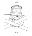
- Figs. 9 to 13 An important difference exhibited by the embodiment of Figs. 9 to 13 is that the rotatable head 204 is significantly smaller in diameter than in the previous embodiments. This can be seen by comparing the rotating head as shown in Fig. 12 with Fig.1b which shows the rotating parts 6, 8, 14, 18, 20 of the first embodiment.
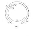
- the base plate 6 and semi-circular channel 8 are both as wide as the loop of wire issued and rotate at this diameter.
- the wire 46 is issued into one of the wire guides 260a, 260b which do not rotate; it is not guided out to its maximum diameter by the head.
- the rotating head having the diameter D 1 of the initial wire loop it has the much smaller diameter D 2 . This allows the overall size of the machine including housing etc. (not shown here to be much smaller and lighter). It also reduces the torque required of the motor further enhancing the size and weight benefits.
- the head 204 is open to the side in the region of the wire issuing means (rollers 238 etc.) but is closed off at the bottom by a tying plate 270.
- the tying plate is circular with two generally radial slots 272, 274, which extend to the edge of the plate. Each slot has a'double-back' portion 272a, 272b at its radially innermost end which helps to prevent the wire slipping back out along the slot once it has passed along it.
- a domed depression 209 for turning down the ends of the wire as previously described.
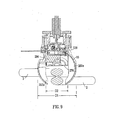
- Fig. 9 shows the state of the machine immediately before a tying operation is commenced.
- the guide 260a on the wire issuing side has a length of wire 46 already received in it.
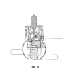
- the wire 46 begins immediately to cross the gap between the channels 260, under the reinforcing bars 2, and return back towards the receiving mechanism (clutch etc., not shown) on the other side of the head 204 to the issuing rollers 238). This is shown in Figs. 11 and 12 .
- the wire 46 does not pass through the tie plate 270.
- the wire 46 starts at the bottom end of the guide member 260a rather than where it first enters the head 204 from the spool (not shown), it has less distance to travel and the loop is completed more quickly - in approximately two thirds the time. This makes the overall tying operation quicker which is advantageous in terms of efficiency.
- the motor is stopped. This allows safe operator intervention without risking damage to the machine or the operator should the wire have become tangled.
- the wire is first retracted back to the position shown in Fig. 9 (i.e. the pre-feed position). In other embodiments however it could simply be left where it is for the operator to deal with, e.g. by cutting it manually; or automatically cut to allow it to be released by the operator.
- the wire travels around the inside surfaces of the guide members 260a, 260b and so in contrast to the containment channels 160, the guide members do provide some guiding function.
- the arcuate set on the wire is still significant as it allows the wire to pass through the open volume between the issuing part of the head 204 and the top end of the guide member 260a. This in turn enables the reduction in diameter of the head discussed.
- the set on the wire also obviates any need to provide a shuttle or the like to guide the wire across the gap between the guides 260a, 260b.
- the feed mechanism is reversed as described before to pull the wire taut around the bars 2.
- This causes the wire 46 to pass into the slots 272, 274 on either side of the tie plate until it is caught in the double-back portions 272a, 274a.
- the head 204 including the tie plate 270 is then rotated to twist the wire exactly as in the previous embodiments.
- the feed motor is operated once again just long enough for the wire 46 to advance to the end of the first guide member 260a, i.e. to reach the situation shown in Fig. 9 . This can be carried out while the operator is moving the machine to the next tie site but reduces the time taken for the actual tying operation so allowing the overall work rate which can be achieved to increase.
- one of the wire feed rollers 238 does not have a smooth surface but rather has a circumferentially spaced series of teeth. By being of a harder material than the wire, this imparts the wire with a serrated surface texture which increases the grip which the receiving side clutch can apply to it. Since the serrated roller is disposed on one side of the wire only, only part of the circumference of the wire will be conditioned in this way. Of course many other types of conditioning could be applied e.g. smoothing or lubricating, or other sorts of roughening. Equally the conditioning could be applied at a different point in the machine or at several points.
- FIG. 14 A feature of a yet further embodiment of the invention is shown in Fig. 14.
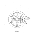
- the outer circumference of the rotary head 304 has an inclined notch 372 formed in it.
- a pin 374 is spring-mounted to a barrel 376 which is fixed to the body of the apparatus (not shown) and is arranged so as to be pressed into the notch 372 when they are rotationally aligned. When they are not aligned the pin 372 is forced back into the barrel 376 by the circumference of the head 304.
- the head can thus be rotated anti-clockwise to twist the wire as previously described; and then the rotation reversed to return the head to the park position shown in Fig. 15 .
- This ratchet arrangement has the advantage of being a simple and reliable way of parking the head.
- variable force clamping mechanisms e.g. involving feedback of the tension in the wire; or indeed it may not be necessary to provide any such variable force mechanism.
Landscapes
- Engineering & Computer Science (AREA)
- Architecture (AREA)
- Mechanical Engineering (AREA)
- Civil Engineering (AREA)
- Structural Engineering (AREA)
- Basic Packing Technique (AREA)
- Hand Tools For Fitting Together And Separating, Or Other Hand Tools (AREA)
Claims (15)
- Appareil pour attacher un fil (46) autour d'un ou de plusieurs objets (2) comprenant des moyens (38a, 38b, 38c, 8) pour faire passer ledit fil (46) dans une boucle autour des objets (2) et des moyens (4) pour tordre les extrémités de ladite boucle en même temps, lesdits moyens de torsion (4) comprenant au moins des moyens de préhension (32, 32a, 36) pour la préhension du fil (46), caractérisé en ce que lesdits moyens de préhension (32, 32a, 36) sont adaptés pour fournir une force de préhension variable de manière à appliquer une tension prédéterminée sur le fil (46) au moins pendant une première phase de torsion.
- Appareil selon la revendication 1, dans lequel lesdits moyens de préhension (32, 32a, 36) comprennent un ou plusieurs mécanismes d'embrayage de force variable (32).
- Appareil selon la revendication 2, dans lequel le ou chaque mécanisme d'embrayage (32) comprend un élément (32a) sollicité élastiquement sur le fil (46) et formé pour augmenter la force de serrage sur le fil (46) lorsque le fil est tiré devant lui.
- Appareil selon la revendication 1, 2 ou 3, comprenant en outre des moyens pour fournir une rétroaction de la quantité de tension dans le fil.
- Appareil selon l'une quelconque des revendications précédentes, comprenant une surface de guidage (9) agencée de manière à dévier le fil (46) pendant qu'il est tordu de telle sorte que les extrémités du fil (46) se terminent en pointant au moins partiellement dans la direction des objets (2) étant liés.
- Appareil selon l'une quelconque des revendications précédentes, dans lequel lesdits moyens de torsion comprennent une tête rotative (4) agencée pour tourner afin de tordre les extrémités du fil (46) ensemble.
- Appareil selon la revendication 6, dans lequel ladite tête rotative (4) est plus petite en diamètre que le diamètre initial de la boucle du fil (46).
- Appareil selon la revendication 6 ou 7, comprenant des moyens de stationnement pour le retour de la tête à une position de stationnement prédéterminée ou à l'une d'une pluralité de positions prédéterminées de stationnement.
- Appareil selon l'une quelconque des revendications précédentes, comprenant des moyens (14, 22, 40) pour découper le fil (46) et agencés pour pré-alimenter une longueur de fil (46) au-delà des moyens de découpe (14, 22, 40) à la fin d'une opération d'attache.
- Appareil selon la revendication 9 agencé pour pré-alimenter ledit fil (46) une fois que la ou une tête rotative (4) a été verrouillée pour empêcher la rotation.
- Appareil selon l'une quelconque des revendications précédentes, comprenant des moyens de délivrance et de réception de fil (40, 8, 12) agencés pour passer un fil (46) animé d'un arc de cercle situé dans une boucle autour des objets (2) des moyens de délivrance (40, 8) aux moyens de réception (12).
- Appareil selon la revendication 11 pour déterminer si le fil (46) n'a pas été reçu correctement par les moyens de réception (12).
- Appareil selon la revendication 12, qui est configuré pour libérer le fil (46) si lesdits moyens de détermination (46) déterminent que le fil n'a pas été correctement reçu par les moyens de réception (12).
- Appareil selon l'une quelconque des revendications précédentes, comprenant des moyens de détection (44) pour détecter la présence d'un objet légitime (2) à attacher dans une zone à travers laquelle le fil (46) passe, dans lequel lesdits moyens de détection détectent la présence d'un matériau approprié pour l'objet (2).
- Appareil selon l'une quelconque des revendications précédentes, comprenant des moyens de conditionnement (238) permettant de modifier les propriétés de frottement de la surface du fil (46).
Priority Applications (1)
| Application Number | Priority Date | Filing Date | Title |
|---|---|---|---|
| EP13176935.8A EP2666932B1 (fr) | 2005-10-10 | 2006-10-09 | Liaison d'objets |
Applications Claiming Priority (4)
| Application Number | Priority Date | Filing Date | Title |
|---|---|---|---|
| GB0520523A GB0520523D0 (en) | 2005-10-10 | 2005-10-10 | Object binding |
| GB0520934A GB0520934D0 (en) | 2005-10-14 | 2005-10-14 | Object binding |
| GB0525885A GB0525885D0 (en) | 2005-12-20 | 2005-12-20 | Object binding |
| PCT/GB2006/003749 WO2007042785A2 (fr) | 2005-10-10 | 2006-10-09 | Liaison d'objets |
Related Child Applications (2)
| Application Number | Title | Priority Date | Filing Date |
|---|---|---|---|
| EP13176935.8A Division-Into EP2666932B1 (fr) | 2005-10-10 | 2006-10-09 | Liaison d'objets |
| EP13176935.8A Division EP2666932B1 (fr) | 2005-10-10 | 2006-10-09 | Liaison d'objets |
Publications (2)
| Publication Number | Publication Date |
|---|---|
| EP1951973A2 EP1951973A2 (fr) | 2008-08-06 |
| EP1951973B1 true EP1951973B1 (fr) | 2014-12-10 |
Family
ID=37462394
Family Applications (2)
| Application Number | Title | Priority Date | Filing Date |
|---|---|---|---|
| EP06794700.2A Active EP1951973B1 (fr) | 2005-10-10 | 2006-10-09 | Appareil pour la liaison d'objets |
| EP13176935.8A Not-in-force EP2666932B1 (fr) | 2005-10-10 | 2006-10-09 | Liaison d'objets |
Family Applications After (1)
| Application Number | Title | Priority Date | Filing Date |
|---|---|---|---|
| EP13176935.8A Not-in-force EP2666932B1 (fr) | 2005-10-10 | 2006-10-09 | Liaison d'objets |
Country Status (7)
| Country | Link |
|---|---|
| US (3) | US9593496B2 (fr) |
| EP (2) | EP1951973B1 (fr) |
| CN (2) | CN102720366B (fr) |
| AU (1) | AU2006301032A1 (fr) |
| BR (1) | BRPI0617434A2 (fr) |
| CA (1) | CA2625483A1 (fr) |
| WO (1) | WO2007042785A2 (fr) |
Families Citing this family (35)
| Publication number | Priority date | Publication date | Assignee | Title |
|---|---|---|---|---|
| EP1951973B1 (fr) | 2005-10-10 | 2014-12-10 | Tymatic Ltd. | Appareil pour la liaison d'objets |
| JP5126101B2 (ja) * | 2008-05-19 | 2013-01-23 | マックス株式会社 | 鉄筋結束機 |
| TWI516415B (zh) | 2008-12-12 | 2016-01-11 | 美克司股份有限公司 | 鐵筋捆紮機 |
| GB0902179D0 (en) * | 2009-02-10 | 2009-03-25 | Tymatic Ltd | Machine for binding reinforcement bars |
| GB0906575D0 (en) * | 2009-04-16 | 2009-05-20 | Tymatic Ltd | Wire binding machines |
| GB0908106D0 (en) * | 2009-05-11 | 2009-06-24 | Tymatic Ltd | Machine for binding reinforcement bars |
| GB0908105D0 (en) * | 2009-05-11 | 2009-06-24 | Tymatic Ltd | Machine for binding reinforcemnet bars |
| US9272799B2 (en) | 2011-10-04 | 2016-03-01 | Signode Industrial Group Llc | Sealing tool for strap |
| US9719331B2 (en) | 2012-05-13 | 2017-08-01 | Alexander H. Slocum | Method and apparatus for bringing under control an uncontrolled flow through a flow device |
| DE102012216831A1 (de) | 2012-09-19 | 2014-03-20 | Wobben Properties Gmbh | Vorrichtung und Verfahren zum automatischen Verdrillen von Metalldrähten, insbesondere zum Verbinden benachbarter, vorzugsweise sich überkreuzender Strukturelemente |
| CN103726663B (zh) * | 2013-11-25 | 2015-12-09 | 成都市翻鑫家科技有限公司 | 新型钢筋绑扎钩 |
| JP6417772B2 (ja) * | 2014-07-31 | 2018-11-07 | マックス株式会社 | 鉄筋結束機 |
| JP6471432B2 (ja) * | 2014-09-03 | 2019-02-20 | 株式会社大林組 | 鉄筋結束装置及び鉄筋結束方法 |
| JP6473394B2 (ja) * | 2015-07-13 | 2019-02-20 | 株式会社マキタ | 鉄筋結束装置 |
| US10486645B2 (en) * | 2015-11-20 | 2019-11-26 | Ford Global Technologies, Llc | Lock for vehicle active front steering system |
| US10577137B2 (en) | 2015-12-09 | 2020-03-03 | Signode Industrial Group Llc | Electrically powered combination hand-held notch-type strapping tool |
| SE539617C2 (sv) | 2016-02-12 | 2017-10-17 | Construction Tools Pc Ab | Knutplatta för en najningsmaskin och en najningsmaskin innefattande knutplattan |
| CN106143984B (zh) * | 2016-08-29 | 2018-07-31 | 山东吉威医疗制品有限公司 | 一种金属支架捆绑机 |
| SE540858C2 (sv) * | 2017-04-06 | 2018-12-04 | Husqvarna Ab | Anordning för att styra en tråd i en najningsmaskin och en najningsmaskin innefattande anordningen samt en najningsprocess |
| CN108868158B (zh) * | 2018-07-27 | 2020-10-30 | 中交一公局重庆城市建设发展有限公司 | 一种装配式建筑钢筋定位方法 |
| JP7379941B2 (ja) * | 2018-09-07 | 2023-11-15 | マックス株式会社 | 結束機 |
| JP7163679B2 (ja) * | 2018-09-07 | 2022-11-01 | マックス株式会社 | 結束機 |
| NZ773631A (en) * | 2018-09-07 | 2026-03-27 | Max Co Ltd | Binding machine |
| WO2020050388A1 (fr) | 2018-09-07 | 2020-03-12 | マックス株式会社 | Machine de liaison |
| JP7275506B2 (ja) | 2018-09-07 | 2023-05-18 | マックス株式会社 | 結束機 |
| US11174051B2 (en) | 2019-02-15 | 2021-11-16 | Samuel, Son & Co. (Usa) Inc. | Hand held strapping tool |
| JP7319849B2 (ja) * | 2019-07-05 | 2023-08-02 | 株式会社マキタ | 鉄筋結束機およびそれを用いた結束方法 |
| CN114599849B (zh) * | 2019-10-28 | 2024-05-28 | 胡斯华纳有限公司 | 包括线锁定机构和控制该线锁定机构的控制单元的钢筋捆扎装置 |
| CN111236658B (zh) * | 2020-03-28 | 2020-12-15 | 重庆吉禾建筑工程有限公司 | 一种建筑用捆扎铁丝装置 |
| IT202000021862A1 (it) * | 2020-09-16 | 2022-03-16 | Schnell Spa | Metodo ed apparecchiatura per legare fili metallici e simili prodotti |
| CN112343348B (zh) * | 2020-10-27 | 2021-11-30 | 雷磊 | 一种钢筋角度连接装置 |
| JP7771550B2 (ja) * | 2021-07-30 | 2025-11-18 | マックス株式会社 | 結束機 |
| JP7790082B2 (ja) * | 2021-10-20 | 2025-12-23 | マックス株式会社 | 結束機 |
| US12397943B2 (en) | 2022-11-29 | 2025-08-26 | Samuel, Son & Co. (Usa) Inc. | Handheld strapping device |
| SE546542C2 (en) | 2022-12-15 | 2024-11-26 | Husqvarna Ab | A rebar wire tying device with blank fire reset function |
Family Cites Families (50)
| Publication number | Priority date | Publication date | Assignee | Title |
|---|---|---|---|---|
| US1809566A (en) | 1928-05-10 | 1931-06-09 | Acme Steel Co | Gripping dog |
| US2919894A (en) | 1955-10-19 | 1960-01-05 | Sharon Steel Corp | Strap stretching tool construction |
| US3028885A (en) | 1958-06-02 | 1962-04-10 | Signode Steel Strapping Co | Power strap tensioning tool |
| US3169559A (en) * | 1961-03-02 | 1965-02-16 | Jr Loren F Working | Wire tying tool |
| DE1215142B (de) * | 1964-07-09 | 1966-04-28 | Bayer Ag | Verfahren zur Herstellung von araliphatischen Isonitrilen |
| FR1576602A (fr) | 1968-06-12 | 1969-08-01 | ||
| US3632969A (en) | 1969-05-08 | 1972-01-04 | Texas Instruments Inc | Electronic printhead protection |
| US3632959A (en) | 1970-06-15 | 1972-01-04 | Crc Crose Int Inc | Exchangeable cartridge unit for automatic welders |
| US3718798A (en) | 1971-06-21 | 1973-02-27 | Crc Crose Int Inc | Traveling welding apparatus |
| AT349861B (de) | 1976-05-25 | 1979-04-25 | Evg Entwicklung Verwert Ges | Bindewerkzeug zum verdrillen der freien enden eines bindedrahtes und gitterbindemaschine mit solchen werkzeugen |
| DE2804300A1 (de) * | 1978-02-01 | 1979-08-02 | Adolf Runkel | Verfahren und vorrichtung zum verbinden bzw. roedeln von mindestens zwei staeben, stangen o.dgl. |
| FR2491527A1 (fr) | 1980-10-07 | 1982-04-09 | Lafon Guy | Machine portative pour realiser automatiquement les ligatures sur des armatures de beton arme, et procede de fonctionnement |
| US4362192A (en) * | 1981-03-05 | 1982-12-07 | Furlong Donn B | Wire tying power tool |
| FR2502582A1 (fr) | 1981-03-26 | 1982-10-01 | Grenon Rene | Systeme de torsadage de fils metalliques |
| DE3419596A1 (de) * | 1983-05-30 | 1984-12-06 | Adolf 5630 Remscheid Runkel | Verfahren zum verbinden zweier sich kreuzender staebe und vorrichtung zum durchfuehren des verfahrens |
| FR2552364B1 (fr) | 1983-09-23 | 1985-12-20 | Lafon Guy | Dispositif pour effectuer des ligatures, notamment avec un fil metallique |
| US4655264A (en) | 1983-10-27 | 1987-04-07 | Ben Clements & Sons, Inc. | Twist tying machine |
| CH648085A5 (en) | 1984-07-26 | 1985-02-28 | Gamper & Co Ag | Unit for twisting two straight wire ends |
| US5004020A (en) | 1988-01-21 | 1991-04-02 | Newtech Products, Inc. | Wire twisting apparatus |
| US4953598A (en) | 1989-04-13 | 1990-09-04 | Mccavey William M | Wire tying tool for concrete reinforcing steel |
| US5368278A (en) * | 1989-11-15 | 1994-11-29 | Paul Hellermann Gmbh | Appliance and process for tying an article, especially a cable harness |
| CN2072470U (zh) * | 1990-06-26 | 1991-03-06 | 黄确亮 | 扎丝钳 |
| SE9003176D0 (sv) * | 1990-10-04 | 1990-10-04 | Peter Hoyaukin | Saett och maskin foer sammanbindning av korsande staenger |
| AU2436892A (en) * | 1991-08-02 | 1993-03-02 | Gateway Construction Company, Inc. | Power rebar tying tool |
| ES2057996B1 (es) | 1991-11-29 | 1995-10-16 | Tecnologia Del Automatismo S L | Perfeccionamientos en maquinas para devanar y atar |
| MY130074A (en) * | 1992-02-28 | 2007-05-31 | Bentac Co Ltd | Method and apparatus for tying one more articles |
| DE69530587T2 (de) | 1994-06-24 | 2004-03-25 | Talon Industries, LLC, Vail | Kabelbindewerkzeug mit antriebsmechanismus |
| KR100423385B1 (ko) * | 1995-02-17 | 2004-07-19 | 니혼 오토매틱머신 카부시기가이샤 | 물품의결속방법및결속장치 |
| US5678613A (en) * | 1995-06-30 | 1997-10-21 | Max Co., Ltd. | Reinforcement binding machine |
| DE19528022C2 (de) | 1995-07-31 | 1999-02-11 | Bau Und Maschinenschlosserei F | Transportable Vorrichtung zum Verbinden von Bewehrungseisen |
| JP2923242B2 (ja) * | 1996-03-15 | 1999-07-26 | 大木樹脂工業株式会社 | 鉄筋結束機 |
| US5826629A (en) * | 1997-01-17 | 1998-10-27 | John E. Burford | Pneumatic wire tying apparatus |
| US5778945A (en) | 1997-03-14 | 1998-07-14 | Tempel Steel Company, Inc. | Automatic wire twister |
| DE19806995C2 (de) | 1998-02-19 | 2001-07-05 | Hunklinger Jun | Verfahren und Vorrichtung zum Verbinden von Gegenständen mittels Flechtdrahtes |
| US6041833A (en) | 1998-05-26 | 2000-03-28 | Suric; Marijan | Wire clamping and twisting device for use with cordless electric screwdriver |
| JP3010353B1 (ja) | 1998-08-26 | 2000-02-21 | ジャパンライフ株式会社 | 鉄筋メッシュ用結束機 |
| CN1122618C (zh) * | 1999-04-28 | 2003-10-01 | 肖广勇 | 钢筋绑扎器 |
| US6401766B1 (en) * | 1999-07-23 | 2002-06-11 | Max Co., Ltd. | Binding machine for reinforcing bars |
| US6745677B2 (en) * | 2001-07-12 | 2004-06-08 | Illinois Tool Works, Inc. | Strapping machine with easy access and feed guides |
| US7143792B2 (en) | 2001-07-19 | 2006-12-05 | Max Co., Ltd. | Reinforcing steel bar tying machine |
| JP3624873B2 (ja) | 2001-10-29 | 2005-03-02 | マックス株式会社 | 鉄筋結束機の結束線捩り装置 |
| JP3680804B2 (ja) | 2002-03-12 | 2005-08-10 | マックス株式会社 | 鉄筋結束機 |
| JP2004142813A (ja) | 2002-10-28 | 2004-05-20 | Max Co Ltd | 鉄筋結束機 |
| SE0302276L (sv) | 2003-03-18 | 2004-04-06 | Peter Hoyaukin | Sätt och maskin för sammanbindning av långsträckta föremål |
| CN2652552Y (zh) * | 2003-10-17 | 2004-11-03 | 李国昌 | 钢筋捆绑扎线器 |
| EP1951973B1 (fr) | 2005-10-10 | 2014-12-10 | Tymatic Ltd. | Appareil pour la liaison d'objets |
| GB0520523D0 (en) * | 2005-10-10 | 2005-11-16 | Tymatic Ltd | Object binding |
| GB0906575D0 (en) | 2009-04-16 | 2009-05-20 | Tymatic Ltd | Wire binding machines |
| GB0908105D0 (en) | 2009-05-11 | 2009-06-24 | Tymatic Ltd | Machine for binding reinforcemnet bars |
| GB0908106D0 (en) | 2009-05-11 | 2009-06-24 | Tymatic Ltd | Machine for binding reinforcement bars |
-
2006
- 2006-10-09 EP EP06794700.2A patent/EP1951973B1/fr active Active
- 2006-10-09 CN CN201210111573.2A patent/CN102720366B/zh active Active
- 2006-10-09 BR BRPI0617434-5A patent/BRPI0617434A2/pt active IP Right Grant
- 2006-10-09 AU AU2006301032A patent/AU2006301032A1/en not_active Abandoned
- 2006-10-09 CA CA002625483A patent/CA2625483A1/fr not_active Abandoned
- 2006-10-09 CN CN201510673195.0A patent/CN105386602B/zh active Active
- 2006-10-09 WO PCT/GB2006/003749 patent/WO2007042785A2/fr not_active Ceased
- 2006-10-09 EP EP13176935.8A patent/EP2666932B1/fr not_active Not-in-force
- 2006-10-09 US US12/089,896 patent/US9593496B2/en active Active
-
2017
- 2017-02-02 US US15/423,354 patent/US10240355B2/en not_active Expired - Fee Related
-
2019
- 2019-03-08 US US16/296,913 patent/US11473322B2/en active Active
Also Published As
| Publication number | Publication date |
|---|---|
| US11473322B2 (en) | 2022-10-18 |
| WO2007042785A2 (fr) | 2007-04-19 |
| US20170145704A1 (en) | 2017-05-25 |
| CA2625483A1 (fr) | 2007-04-19 |
| US10240355B2 (en) | 2019-03-26 |
| CN105386602A (zh) | 2016-03-09 |
| EP2666932A1 (fr) | 2013-11-27 |
| WO2007042785A3 (fr) | 2007-08-02 |
| US20110155277A1 (en) | 2011-06-30 |
| US9593496B2 (en) | 2017-03-14 |
| EP1951973A2 (fr) | 2008-08-06 |
| US20190203486A1 (en) | 2019-07-04 |
| EP2666932B1 (fr) | 2016-07-20 |
| CN105386602B (zh) | 2019-05-17 |
| CN102720366A (zh) | 2012-10-10 |
| CN102720366B (zh) | 2016-04-06 |
| BRPI0617434A2 (pt) | 2011-07-26 |
| AU2006301032A1 (en) | 2007-04-19 |
Similar Documents
| Publication | Publication Date | Title |
|---|---|---|
| US11473322B2 (en) | Apparatus for tying wire around one or more objects | |
| CA3014611C (fr) | Machine lieuse de barres de renfort | |
| EP2419582B1 (fr) | Machines à ficeler au moyen de fil de fer | |
| JP7718464B2 (ja) | 結束機 | |
| CN101300395A (zh) | 用于将物件绑扎到一起的设备 | |
| US20120132088A1 (en) | Machine for binding reinforcement bars | |
| WO2008044002A2 (fr) | Machines à lier le fil | |
| WO2016128332A1 (fr) | Applicateur pour étiquettes d'identification d'animaux | |
| BRPI0617434B1 (pt) | Apparatus to tie a wire | |
| WO2010092337A1 (fr) | Machine pour la liaison de barres de renfort | |
| SE527781C2 (sv) | Maskin för sammanbindning av långsträckta föremål |
Legal Events
| Date | Code | Title | Description |
|---|---|---|---|
| PUAI | Public reference made under article 153(3) epc to a published international application that has entered the european phase |
Free format text: ORIGINAL CODE: 0009012 |
|
| 17P | Request for examination filed |
Effective date: 20080509 |
|
| AK | Designated contracting states |
Kind code of ref document: A2 Designated state(s): AT BE BG CH CY CZ DE DK EE ES FI FR GB GR HU IE IS IT LI LT LU LV MC NL PL PT RO SE SI SK TR |
|
| 17Q | First examination report despatched |
Effective date: 20110707 |
|
| DAX | Request for extension of the european patent (deleted) | ||
| REG | Reference to a national code |
Ref country code: DE Ref legal event code: R079 Ref document number: 602006043971 Country of ref document: DE Free format text: PREVIOUS MAIN CLASS: E04G0021120000 Ipc: B65B0013280000 |
|
| GRAP | Despatch of communication of intention to grant a patent |
Free format text: ORIGINAL CODE: EPIDOSNIGR1 |
|
| RIC1 | Information provided on ipc code assigned before grant |
Ipc: B65B 13/28 20060101AFI20140424BHEP Ipc: E04G 21/12 20060101ALI20140424BHEP |
|
| INTG | Intention to grant announced |
Effective date: 20140509 |
|
| GRAS | Grant fee paid |
Free format text: ORIGINAL CODE: EPIDOSNIGR3 |
|
| GRAA | (expected) grant |
Free format text: ORIGINAL CODE: 0009210 |
|
| AK | Designated contracting states |
Kind code of ref document: B1 Designated state(s): AT BE BG CH CY CZ DE DK EE ES FI FR GB GR HU IE IS IT LI LT LU LV MC NL PL PT RO SE SI SK TR |
|
| REG | Reference to a national code |
Ref country code: GB Ref legal event code: FG4D |
|
| REG | Reference to a national code |
Ref country code: CH Ref legal event code: EP |
|
| REG | Reference to a national code |
Ref country code: IE Ref legal event code: FG4D |
|
| REG | Reference to a national code |
Ref country code: AT Ref legal event code: REF Ref document number: 700515 Country of ref document: AT Kind code of ref document: T Effective date: 20150115 |
|
| REG | Reference to a national code |
Ref country code: DE Ref legal event code: R096 Ref document number: 602006043971 Country of ref document: DE Effective date: 20150122 |
|
| RAP2 | Party data changed (patent owner data changed or rights of a patent transferred) |
Owner name: CONSTRUCTION TOOLS PC AB |
|
| REG | Reference to a national code |
Ref country code: DE Ref legal event code: R082 Ref document number: 602006043971 Country of ref document: DE Representative=s name: DEHNS, GB |
|
| REG | Reference to a national code |
Ref country code: SE Ref legal event code: TRGR |
|
| REG | Reference to a national code |
Ref country code: AT Ref legal event code: MK05 Ref document number: 700515 Country of ref document: AT Kind code of ref document: T Effective date: 20141210 Ref country code: NL Ref legal event code: VDEP Effective date: 20141210 |
|
| REG | Reference to a national code |
Ref country code: NL Ref legal event code: VDEP Effective date: 20141210 |
|
| PG25 | Lapsed in a contracting state [announced via postgrant information from national office to epo] |
Ref country code: LT Free format text: LAPSE BECAUSE OF FAILURE TO SUBMIT A TRANSLATION OF THE DESCRIPTION OR TO PAY THE FEE WITHIN THE PRESCRIBED TIME-LIMIT Effective date: 20141210 Ref country code: FI Free format text: LAPSE BECAUSE OF FAILURE TO SUBMIT A TRANSLATION OF THE DESCRIPTION OR TO PAY THE FEE WITHIN THE PRESCRIBED TIME-LIMIT Effective date: 20141210 Ref country code: ES Free format text: LAPSE BECAUSE OF FAILURE TO SUBMIT A TRANSLATION OF THE DESCRIPTION OR TO PAY THE FEE WITHIN THE PRESCRIBED TIME-LIMIT Effective date: 20141210 |
|
| REG | Reference to a national code |
Ref country code: LT Ref legal event code: MG4D |
|
| PG25 | Lapsed in a contracting state [announced via postgrant information from national office to epo] |
Ref country code: LV Free format text: LAPSE BECAUSE OF FAILURE TO SUBMIT A TRANSLATION OF THE DESCRIPTION OR TO PAY THE FEE WITHIN THE PRESCRIBED TIME-LIMIT Effective date: 20141210 Ref country code: GR Free format text: LAPSE BECAUSE OF FAILURE TO SUBMIT A TRANSLATION OF THE DESCRIPTION OR TO PAY THE FEE WITHIN THE PRESCRIBED TIME-LIMIT Effective date: 20150311 Ref country code: AT Free format text: LAPSE BECAUSE OF FAILURE TO SUBMIT A TRANSLATION OF THE DESCRIPTION OR TO PAY THE FEE WITHIN THE PRESCRIBED TIME-LIMIT Effective date: 20141210 |
|
| PG25 | Lapsed in a contracting state [announced via postgrant information from national office to epo] |
Ref country code: NL Free format text: LAPSE BECAUSE OF FAILURE TO SUBMIT A TRANSLATION OF THE DESCRIPTION OR TO PAY THE FEE WITHIN THE PRESCRIBED TIME-LIMIT Effective date: 20141210 |
|
| PG25 | Lapsed in a contracting state [announced via postgrant information from national office to epo] |
Ref country code: CZ Free format text: LAPSE BECAUSE OF FAILURE TO SUBMIT A TRANSLATION OF THE DESCRIPTION OR TO PAY THE FEE WITHIN THE PRESCRIBED TIME-LIMIT Effective date: 20141210 Ref country code: RO Free format text: LAPSE BECAUSE OF FAILURE TO SUBMIT A TRANSLATION OF THE DESCRIPTION OR TO PAY THE FEE WITHIN THE PRESCRIBED TIME-LIMIT Effective date: 20141210 Ref country code: EE Free format text: LAPSE BECAUSE OF FAILURE TO SUBMIT A TRANSLATION OF THE DESCRIPTION OR TO PAY THE FEE WITHIN THE PRESCRIBED TIME-LIMIT Effective date: 20141210 Ref country code: SK Free format text: LAPSE BECAUSE OF FAILURE TO SUBMIT A TRANSLATION OF THE DESCRIPTION OR TO PAY THE FEE WITHIN THE PRESCRIBED TIME-LIMIT Effective date: 20141210 Ref country code: PT Free format text: LAPSE BECAUSE OF FAILURE TO SUBMIT A TRANSLATION OF THE DESCRIPTION OR TO PAY THE FEE WITHIN THE PRESCRIBED TIME-LIMIT Effective date: 20150410 |
|
| PG25 | Lapsed in a contracting state [announced via postgrant information from national office to epo] |
Ref country code: IS Free format text: LAPSE BECAUSE OF FAILURE TO SUBMIT A TRANSLATION OF THE DESCRIPTION OR TO PAY THE FEE WITHIN THE PRESCRIBED TIME-LIMIT Effective date: 20150410 Ref country code: PL Free format text: LAPSE BECAUSE OF FAILURE TO SUBMIT A TRANSLATION OF THE DESCRIPTION OR TO PAY THE FEE WITHIN THE PRESCRIBED TIME-LIMIT Effective date: 20141210 |
|
| REG | Reference to a national code |
Ref country code: DE Ref legal event code: R097 Ref document number: 602006043971 Country of ref document: DE |
|
| PLBE | No opposition filed within time limit |
Free format text: ORIGINAL CODE: 0009261 |
|
| STAA | Information on the status of an ep patent application or granted ep patent |
Free format text: STATUS: NO OPPOSITION FILED WITHIN TIME LIMIT |
|
| REG | Reference to a national code |
Ref country code: FR Ref legal event code: PLFP Year of fee payment: 10 |
|
| PG25 | Lapsed in a contracting state [announced via postgrant information from national office to epo] |
Ref country code: DK Free format text: LAPSE BECAUSE OF FAILURE TO SUBMIT A TRANSLATION OF THE DESCRIPTION OR TO PAY THE FEE WITHIN THE PRESCRIBED TIME-LIMIT Effective date: 20141210 |
|
| 26N | No opposition filed |
Effective date: 20150911 |
|
| PG25 | Lapsed in a contracting state [announced via postgrant information from national office to epo] |
Ref country code: IT Free format text: LAPSE BECAUSE OF FAILURE TO SUBMIT A TRANSLATION OF THE DESCRIPTION OR TO PAY THE FEE WITHIN THE PRESCRIBED TIME-LIMIT Effective date: 20141210 |
|
| PG25 | Lapsed in a contracting state [announced via postgrant information from national office to epo] |
Ref country code: SI Free format text: LAPSE BECAUSE OF FAILURE TO SUBMIT A TRANSLATION OF THE DESCRIPTION OR TO PAY THE FEE WITHIN THE PRESCRIBED TIME-LIMIT Effective date: 20141210 |
|
| PG25 | Lapsed in a contracting state [announced via postgrant information from national office to epo] |
Ref country code: BE Free format text: LAPSE BECAUSE OF FAILURE TO SUBMIT A TRANSLATION OF THE DESCRIPTION OR TO PAY THE FEE WITHIN THE PRESCRIBED TIME-LIMIT Effective date: 20141210 Ref country code: LU Free format text: LAPSE BECAUSE OF FAILURE TO SUBMIT A TRANSLATION OF THE DESCRIPTION OR TO PAY THE FEE WITHIN THE PRESCRIBED TIME-LIMIT Effective date: 20151009 |
|
| REG | Reference to a national code |
Ref country code: CH Ref legal event code: PL |
|
| PG25 | Lapsed in a contracting state [announced via postgrant information from national office to epo] |
Ref country code: MC Free format text: LAPSE BECAUSE OF FAILURE TO SUBMIT A TRANSLATION OF THE DESCRIPTION OR TO PAY THE FEE WITHIN THE PRESCRIBED TIME-LIMIT Effective date: 20141210 |
|
| REG | Reference to a national code |
Ref country code: IE Ref legal event code: MM4A |
|
| PG25 | Lapsed in a contracting state [announced via postgrant information from national office to epo] |
Ref country code: CH Free format text: LAPSE BECAUSE OF NON-PAYMENT OF DUE FEES Effective date: 20151031 Ref country code: LI Free format text: LAPSE BECAUSE OF NON-PAYMENT OF DUE FEES Effective date: 20151031 |
|
| REG | Reference to a national code |
Ref country code: FR Ref legal event code: PLFP Year of fee payment: 11 |
|
| PG25 | Lapsed in a contracting state [announced via postgrant information from national office to epo] |
Ref country code: IE Free format text: LAPSE BECAUSE OF NON-PAYMENT OF DUE FEES Effective date: 20151009 |
|
| PG25 | Lapsed in a contracting state [announced via postgrant information from national office to epo] |
Ref country code: BG Free format text: LAPSE BECAUSE OF FAILURE TO SUBMIT A TRANSLATION OF THE DESCRIPTION OR TO PAY THE FEE WITHIN THE PRESCRIBED TIME-LIMIT Effective date: 20141210 Ref country code: HU Free format text: LAPSE BECAUSE OF FAILURE TO SUBMIT A TRANSLATION OF THE DESCRIPTION OR TO PAY THE FEE WITHIN THE PRESCRIBED TIME-LIMIT; INVALID AB INITIO Effective date: 20061009 |
|
| PG25 | Lapsed in a contracting state [announced via postgrant information from national office to epo] |
Ref country code: CY Free format text: LAPSE BECAUSE OF FAILURE TO SUBMIT A TRANSLATION OF THE DESCRIPTION OR TO PAY THE FEE WITHIN THE PRESCRIBED TIME-LIMIT Effective date: 20141210 |
|
| PG25 | Lapsed in a contracting state [announced via postgrant information from national office to epo] |
Ref country code: TR Free format text: LAPSE BECAUSE OF FAILURE TO SUBMIT A TRANSLATION OF THE DESCRIPTION OR TO PAY THE FEE WITHIN THE PRESCRIBED TIME-LIMIT Effective date: 20141210 |
|
| REG | Reference to a national code |
Ref country code: FR Ref legal event code: PLFP Year of fee payment: 12 |
|
| REG | Reference to a national code |
Ref country code: FR Ref legal event code: PLFP Year of fee payment: 13 |
|
| REG | Reference to a national code |
Ref country code: DE Ref legal event code: R082 Ref document number: 602006043971 Country of ref document: DE Representative=s name: DEHNS, GB Ref country code: DE Ref legal event code: R081 Ref document number: 602006043971 Country of ref document: DE Owner name: HUSQVARNA AB, SE Free format text: FORMER OWNER: CONSTRUCTION TOOLS PC AB, KALMAR, SE |
|
| REG | Reference to a national code |
Ref country code: GB Ref legal event code: 732E Free format text: REGISTERED BETWEEN 20190321 AND 20190327 |
|
| REG | Reference to a national code |
Ref country code: DE Ref legal event code: R082 Ref document number: 602006043971 Country of ref document: DE |
|
| P01 | Opt-out of the competence of the unified patent court (upc) registered |
Effective date: 20230419 |
|
| PGFP | Annual fee paid to national office [announced via postgrant information from national office to epo] |
Ref country code: DE Payment date: 20251010 Year of fee payment: 20 |
|
| PGFP | Annual fee paid to national office [announced via postgrant information from national office to epo] |
Ref country code: GB Payment date: 20251013 Year of fee payment: 20 |
|
| PGFP | Annual fee paid to national office [announced via postgrant information from national office to epo] |
Ref country code: FR Payment date: 20251014 Year of fee payment: 20 |
|
| PGFP | Annual fee paid to national office [announced via postgrant information from national office to epo] |
Ref country code: SE Payment date: 20251014 Year of fee payment: 20 |