EP1952509B1 - Groupe moteur-pompe a etancheite amelioree - Google Patents
Groupe moteur-pompe a etancheite amelioree Download PDFInfo
- Publication number
- EP1952509B1 EP1952509B1 EP06807473.1A EP06807473A EP1952509B1 EP 1952509 B1 EP1952509 B1 EP 1952509B1 EP 06807473 A EP06807473 A EP 06807473A EP 1952509 B1 EP1952509 B1 EP 1952509B1
- Authority
- EP
- European Patent Office
- Prior art keywords
- motor
- seal
- housing
- pump
- motor housing
- Prior art date
- Legal status (The legal status is an assumption and is not a legal conclusion. Google has not performed a legal analysis and makes no representation as to the accuracy of the status listed.)
- Not-in-force
Links
- 238000007789 sealing Methods 0.000 title description 21
- 238000012544 monitoring process Methods 0.000 claims description 5
- 238000000034 method Methods 0.000 description 6
- 230000006835 compression Effects 0.000 description 5
- 238000007906 compression Methods 0.000 description 5
- 239000012530 fluid Substances 0.000 description 4
- 229920001296 polysiloxane Polymers 0.000 description 4
- 230000035882 stress Effects 0.000 description 4
- 238000003780 insertion Methods 0.000 description 3
- 230000037431 insertion Effects 0.000 description 3
- 230000003679 aging effect Effects 0.000 description 2
- 230000000694 effects Effects 0.000 description 2
- 238000005538 encapsulation Methods 0.000 description 2
- 238000004804 winding Methods 0.000 description 2
- 230000000712 assembly Effects 0.000 description 1
- 238000000429 assembly Methods 0.000 description 1
- 230000005540 biological transmission Effects 0.000 description 1
- 239000004020 conductor Substances 0.000 description 1
- 230000008878 coupling Effects 0.000 description 1
- 238000010168 coupling process Methods 0.000 description 1
- 238000005859 coupling reaction Methods 0.000 description 1
- 230000001351 cycling effect Effects 0.000 description 1
- 230000001419 dependent effect Effects 0.000 description 1
- 238000013461 design Methods 0.000 description 1
- 238000011161 development Methods 0.000 description 1
- 230000018109 developmental process Effects 0.000 description 1
- 230000002349 favourable effect Effects 0.000 description 1
- 239000007924 injection Substances 0.000 description 1
- 238000002347 injection Methods 0.000 description 1
- 238000004643 material aging Methods 0.000 description 1
- 230000002093 peripheral effect Effects 0.000 description 1
- 230000036316 preload Effects 0.000 description 1
- 238000012360 testing method Methods 0.000 description 1
Images

Classifications
-
- H—ELECTRICITY
- H02—GENERATION; CONVERSION OR DISTRIBUTION OF ELECTRIC POWER
- H02K—DYNAMO-ELECTRIC MACHINES
- H02K5/00—Casings; Enclosures; Supports
- H02K5/04—Casings or enclosures characterised by the shape, form or construction thereof
- H02K5/10—Casings or enclosures characterised by the shape, form or construction thereof with arrangements for protection from ingress, e.g. water or fingers
-
- B—PERFORMING OPERATIONS; TRANSPORTING
- B60—VEHICLES IN GENERAL
- B60T—VEHICLE BRAKE CONTROL SYSTEMS OR PARTS THEREOF; BRAKE CONTROL SYSTEMS OR PARTS THEREOF, IN GENERAL; ARRANGEMENT OF BRAKING ELEMENTS ON VEHICLES IN GENERAL; PORTABLE DEVICES FOR PREVENTING UNWANTED MOVEMENT OF VEHICLES; VEHICLE MODIFICATIONS TO FACILITATE COOLING OF BRAKES
- B60T8/00—Arrangements for adjusting wheel-braking force to meet varying vehicular or ground-surface conditions, e.g. limiting or varying distribution of braking force
- B60T8/32—Arrangements for adjusting wheel-braking force to meet varying vehicular or ground-surface conditions, e.g. limiting or varying distribution of braking force responsive to a speed condition, e.g. acceleration or deceleration
- B60T8/34—Arrangements for adjusting wheel-braking force to meet varying vehicular or ground-surface conditions, e.g. limiting or varying distribution of braking force responsive to a speed condition, e.g. acceleration or deceleration having a fluid pressure regulator responsive to a speed condition
- B60T8/36—Arrangements for adjusting wheel-braking force to meet varying vehicular or ground-surface conditions, e.g. limiting or varying distribution of braking force responsive to a speed condition, e.g. acceleration or deceleration having a fluid pressure regulator responsive to a speed condition including a pilot valve responding to an electromagnetic force
- B60T8/3615—Electromagnetic valves specially adapted for anti-lock brake and traction control systems
- B60T8/3675—Electromagnetic valves specially adapted for anti-lock brake and traction control systems integrated in modulator units
- B60T8/368—Electromagnetic valves specially adapted for anti-lock brake and traction control systems integrated in modulator units combined with other mechanical components, e.g. pump units, master cylinders
-
- F—MECHANICAL ENGINEERING; LIGHTING; HEATING; WEAPONS; BLASTING
- F04—POSITIVE - DISPLACEMENT MACHINES FOR LIQUIDS; PUMPS FOR LIQUIDS OR ELASTIC FLUIDS
- F04B—POSITIVE-DISPLACEMENT MACHINES FOR LIQUIDS; PUMPS
- F04B1/00—Multi-cylinder machines or pumps characterised by number or arrangement of cylinders
- F04B1/04—Multi-cylinder machines or pumps characterised by number or arrangement of cylinders having cylinders in star- or fan-arrangement
- F04B1/0404—Details or component parts
- F04B1/0448—Sealing means, e.g. for shafts or housings
-
- F—MECHANICAL ENGINEERING; LIGHTING; HEATING; WEAPONS; BLASTING
- F04—POSITIVE - DISPLACEMENT MACHINES FOR LIQUIDS; PUMPS FOR LIQUIDS OR ELASTIC FLUIDS
- F04B—POSITIVE-DISPLACEMENT MACHINES FOR LIQUIDS; PUMPS
- F04B17/00—Pumps characterised by combination with, or adaptation to, specific driving engines or motors
- F04B17/03—Pumps characterised by combination with, or adaptation to, specific driving engines or motors driven by electric motors
-
- H—ELECTRICITY
- H02—GENERATION; CONVERSION OR DISTRIBUTION OF ELECTRIC POWER
- H02K—DYNAMO-ELECTRIC MACHINES
- H02K7/00—Arrangements for handling mechanical energy structurally associated with dynamo-electric machines, e.g. structural association with mechanical driving motors or auxiliary dynamo-electric machines
- H02K7/06—Means for converting reciprocating motion into rotary motion or vice versa
- H02K7/075—Means for converting reciprocating motion into rotary motion or vice versa using crankshafts or eccentrics
-
- Y—GENERAL TAGGING OF NEW TECHNOLOGICAL DEVELOPMENTS; GENERAL TAGGING OF CROSS-SECTIONAL TECHNOLOGIES SPANNING OVER SEVERAL SECTIONS OF THE IPC; TECHNICAL SUBJECTS COVERED BY FORMER USPC CROSS-REFERENCE ART COLLECTIONS [XRACs] AND DIGESTS
- Y10—TECHNICAL SUBJECTS COVERED BY FORMER USPC
- Y10T—TECHNICAL SUBJECTS COVERED BY FORMER US CLASSIFICATION
- Y10T29/00—Metal working
- Y10T29/49—Method of mechanical manufacture
- Y10T29/49229—Prime mover or fluid pump making
- Y10T29/49236—Fluid pump or compressor making
Definitions
- the invention relates to a motor-pump unit.
- a motor-pump unit which is in particular a motor vehicle anti-lock braking device.
- This known unit includes a motor housing, a pump housing and an electronics housing.
- the motor housing lies with its one end face in front of the one end face of the pump housing.
- the electronics housing lies with its one end face in front of the other end face of the pump housing.
- the front end faces and through the pump housing lead connecting conductors as electrical supply or control lines between each of the interior of the motor housing on the one hand and the electronics housing on the other.
- the abutting end faces are sealed against each other by circumferential seals lying between them, in particular radially outward.
- These gaskets are generally silicone overmoldings.
- a motor vehicle brake device This contains in axial sandwich-sequential arrangement of a motor housing, a pump housing and an electronics housing. Of the motor housing lead at least two mutually electrically isolated plug-type supply or control lines to the electronics housing.
- the plug-like supply or control lines are firmly fixed on the motor housing side in a base, in particular in a brush plate, axially rigid and freely movable transversely to its longitudinal direction, at least in the sense of tolerance compensation.
- the plug-type supply or control lines are under axial support against the motor housing with an electronics unit in the Electronics housing plug-in contact.
- the brush plate can be supported by at least one outer edge-side Abstutzrippe after aggregate assembly on the outer peripheral surface of the motor housing in Martinezsteckraum the supply and control lines with a press fit, taking into account all tolerances.
- a further motor-pump unit is known, which is in particular a motor vehicle brake device.
- This known unit has an electric motor and driven by this, axially downstream pump. Between the electric motor and the pump a Kardangelenkiano drive connection is provided. This is done via a coupling piece, each with a positive plug-in receptacle for a driven-side rotor shaft end of the electric motor and for a drive-side pump shaft end of the pump.
- the plug-in receptacle is axially conical.
- the rotor shaft end and the pump shaft end have a mutual axial preload in the sense of a play-free rotational drive.
- the EP 1 041 700 A2 relates to a motor-driven unit with a motor unit and a working machine, wherein the motor unit has a motor shaft for driving at least one working element of the working machine, and the motor shaft is mounted at least on one of the working machine end facing a first Lagre.
- the bottom of the motor housing is provided with a groove in which an O-ring is arranged.
- the object of the invention is to provide a new, improved seal for a motor-pump unit.
- Another advantage of the invention is that by the axial compression of the seal and the attachment of the brush plate is improved in the Mötor-pump unit.
- Another advantage of the invention is a higher resistance of the overall system against aging effects, for example in the case of a temperature storage.
- unwanted aging effects of the plastic bearing shield are avoided.
- coarser tolerances on the plastic bearing shield are possible, as well as a refinement of the individual components. This reduces the costs.
- FIG. 1 shows a partial sectional view of a motor-pump unit according to the invention.
- This engine-pump unit include an electric motor M and a pump P. It can be used for example in a motor vehicle as anti-lock braking device.
- the motor M has a cup-shaped motor housing 1.
- a rotor shaft 3 is mounted in bearings.
- a rotor core 8 is firmly connected, so that rotates in operation, the rotor core with the rotor shaft.
- magnetic shells 7 are fixed, which serve to excite the Rotorvers 8 associated rotor winding during operation of the motor.
- the rotor winding is connected to a commutator 9, which is also mounted on the rotor shaft 3 and communicates with brushes, which are supported by a brush plate 11.
- the brush plate 11 forms the end surface of the motor M to the pump housing 2.
- the motor M is axially fixed to an end face of the pump housing 2, for example by a screw connection.
- the rotor shaft 3 of the motor M is guided through the bearing 9 in the pump housing 2 and held there in a pump-side bearing 6.
- a seal 12 is provided, which is preferably a circumferential sealing ring. This causes both a seal of the motor housing 1 from the environment as well as a seal of the motor housing 1 against an inlet of brake fluid, which emerges undesirably from the pump housing 2.
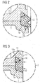
- FIG. 2 shows an enlarged view of the detail X of FIG. 1 in which the seal 12 and the associated receiving elements in the motor housing 1 and the brush plate 11 are included.
- the seal 12 When assembling the motor housing 1 and pump housing 2, the seal 12 is first inserted into the adjacent sealing receiving stages 1a and 11a. It can be seen that the seal 12 protrudes after insertion into the seal receiving stages in the axial direction of the motor housing 1, since it is in the not yet compressed state.
- monitoring surface 16 has an auxiliary function during the assembly process. It can be made in an advantageous manner force monitoring to determine whether a seal is present or not. As a result, it can be ensured that the motor housing is not inadvertently fixedly connected to the transmission housing without a seal having previously been inserted into the seal receiving steps 1a and 11a.
- FIG. 3 shows a further enlarged view, in which the seal 12 is shown in a compressed state.
- This compressed state is brought about by the pump housing 2 being pressed against the motor housing 1 in the axial direction and then fastened thereto, for example using screws.
- the seal 12 is compressed in the axial direction, as indicated by the small arrows in the FIG. 3 is illustrated.
- the seal 12 is pressed into the seal receiving steps 1a and 11a.
- a sealing surface 15 is created by this axial depression of the seal into the seal receiving stages. This seals the motor housing 1 from the environment, so that no surrounding media can reach the interior of the motor housing 1.
- the flanks of the seal receiving steps 1a and 11a are slightly bevelled.
- the bevel of the seal receiving stage 11a of the brush plate is such that the seal receiving stage has flanks which enclose an angle ⁇ which is less than 90 ° and preferably in the range of approximately 45 °.
- a seal of the motor housing according to the present invention in contrast to known seals also meets increased specification requirements for temperature storage and temperature cycling tests, as they are more recently.
- Another significant advantage of the invention is a simplification of the assembly process of the brush system. There is a robust brush system design. Silicone injections, as have been widely used, are not necessary.
Landscapes
- Engineering & Computer Science (AREA)
- Mechanical Engineering (AREA)
- Physics & Mathematics (AREA)
- General Engineering & Computer Science (AREA)
- Electromagnetism (AREA)
- Power Engineering (AREA)
- Fluid Mechanics (AREA)
- Transportation (AREA)
- Valves And Accessory Devices For Braking Systems (AREA)
- Regulating Braking Force (AREA)
- Motor Or Generator Frames (AREA)
Claims (3)
- Groupe moteur-pompe, en particulier pour un dispositif de freinage de véhicule automobile, comprenant :- un moteur (M) comportant un carter de moteur (1) en forme de pot et une plaque porte-balais (11) prévue dans le carter de moteur et- une pompe (P) comportant un carter de pompe (2), dans lequel- le moteur (M) est fixé de manière axiale à une face frontale du carter de pompe (2),- la plaque porte-balais (11) forme la face terminale du moteur (M) côté carter de pompe (2),- la zone de bord du carter de moteur (1) en forme de pot faisant face au carter de pompe (2) présente un gradin de réception de joint (la),- la zone de la plaque porte-balais (11) radialement adjacente à la zone de bord du carter de moteur (1) présente également un gradin de réception de joint (11a) et- dans ces gradins de réception de joint (la, 11a), un joint d'étanchéité (12) est inséré, qui est comprimé de manière axiale par la fixation du carter de pompe (2) au moteur (M).
- Groupe moteur-pompe selon la revendication 1,
caractérisé en ce que
le gradin de réception de joint (11a) de la plaque porte-balais (11) comporte un chanfrein, de telle sorte que le gradin de réception de joint (11a) présente des flancs, qui forment un angle (α) qui est inférieur à 90°. - Groupe moteur-pompe selon la revendication 1 ou 2,
caractérisé en ce que
le gradin de réception de joint (la) du carter de moteur (1) présente un chanfrein sur lequel une surface de surveillance (16) est prévue, sur laquelle la présence du joint d'étanchéité (12) est détectée.
Applications Claiming Priority (2)
| Application Number | Priority Date | Filing Date | Title |
|---|---|---|---|
| DE102005056082 | 2005-11-24 | ||
| PCT/EP2006/067664 WO2007060066A1 (fr) | 2005-11-24 | 2006-10-23 | Groupe moteur-pompe a etancheite amelioree |
Publications (2)
| Publication Number | Publication Date |
|---|---|
| EP1952509A1 EP1952509A1 (fr) | 2008-08-06 |
| EP1952509B1 true EP1952509B1 (fr) | 2016-08-31 |
Family
ID=37651066
Family Applications (1)
| Application Number | Title | Priority Date | Filing Date |
|---|---|---|---|
| EP06807473.1A Not-in-force EP1952509B1 (fr) | 2005-11-24 | 2006-10-23 | Groupe moteur-pompe a etancheite amelioree |
Country Status (4)
| Country | Link |
|---|---|
| US (1) | US20090004035A1 (fr) |
| EP (1) | EP1952509B1 (fr) |
| CN (1) | CN101385220B (fr) |
| WO (1) | WO2007060066A1 (fr) |
Cited By (1)
| Publication number | Priority date | Publication date | Assignee | Title |
|---|---|---|---|---|
| WO2026061677A1 (fr) * | 2024-09-19 | 2026-03-26 | Robert Bosch Gmbh | Agencement de boîtier, générateur de force de freinage |
Families Citing this family (8)
| Publication number | Priority date | Publication date | Assignee | Title |
|---|---|---|---|---|
| DE102009000010A1 (de) | 2009-01-02 | 2010-07-08 | Robert Bosch Gmbh | Elektrisch kommutierte elektrische Maschine |
| JP2012049597A (ja) * | 2010-08-24 | 2012-03-08 | Nikon Corp | 撮像装置 |
| JP5282126B2 (ja) | 2011-07-11 | 2013-09-04 | 日信工業株式会社 | モータポンプ装置 |
| EP2639943B1 (fr) * | 2012-03-15 | 2015-02-25 | Grundfos Holding A/S | Moteur électrique |
| KR101728625B1 (ko) * | 2013-05-20 | 2017-04-19 | 닛본 세이고 가부시끼가이샤 | 모터, 위치결정장치, 반송장치 |
| EP3404806A1 (fr) * | 2017-05-18 | 2018-11-21 | Valeo Autosystemy SP. Z.O.O. | Joint d'étanchéité pour un ensemble moteur électrique, ensemble moteur électrique comprenant un tel joint et moteur d'essuie-glace comprenant un tel ensemble moteur électrique et le joint |
| JP7291913B2 (ja) * | 2018-02-15 | 2023-06-16 | パナソニックIpマネジメント株式会社 | モータ及びそれを備えた電気機器 |
| EP3772800A1 (fr) * | 2019-08-06 | 2021-02-10 | Koninklijke Philips N.V. | Suspension de moteur rigide et étanche à l'eau |
Family Cites Families (11)
| Publication number | Priority date | Publication date | Assignee | Title |
|---|---|---|---|---|
| NL172780C (nl) * | 1974-07-01 | 1983-10-17 | Lucas Benjamins | Afdichtsamenstel voor de samenwerkende aanlegvlakken van deuren en deksels van drukvaten. |
| DE3280372D1 (de) | 1982-03-23 | 1991-12-12 | David V Kimball | Zweiachsenruettelgeraete. |
| EP0117381B1 (fr) * | 1983-02-25 | 1987-11-04 | A.G. Johansons Metallfabrik Aktiebolag | Raccord à bague d'étanchéité pour usage hygiénique |
| DE59300165D1 (de) * | 1993-09-08 | 1995-06-08 | Siemens Ag | Motor-Pumpen-Aggregat, insbesondere Kraftfahrzeug-Antiblockier-Bremsvorrichtung. |
| DE19642133A1 (de) * | 1996-10-12 | 1998-04-16 | Bosch Gmbh Robert | Motor-Pumpen-Einrichtung |
| US6362548B1 (en) * | 1997-04-14 | 2002-03-26 | Donnelly Corporation | Housing with integral gasket components for a rearview mirror actuator assembly |
| US5957464A (en) | 1997-07-11 | 1999-09-28 | Interwave Communications | Split dove-tail gasket channel for round gasket material |
| DE19914258A1 (de) * | 1999-03-29 | 2000-10-05 | Continental Teves Ag & Co Ohg | Motorangetriebenes Aggregat |
| WO2001031198A1 (fr) * | 1999-10-25 | 2001-05-03 | Continental Teves Ag & Co. Ohg | Groupe motopompe |
| DE50208947D1 (de) * | 2002-02-27 | 2007-01-25 | Siemens Ag | Motor-Pumpen-Aggregat, insbesondere für eine Kraftfahrzeug-Bremsvorrichtung |
| JP2005113686A (ja) * | 2003-10-02 | 2005-04-28 | Aisan Ind Co Ltd | 燃料ポンプ |
-
2006
- 2006-10-23 WO PCT/EP2006/067664 patent/WO2007060066A1/fr not_active Ceased
- 2006-10-23 CN CN2006800438274A patent/CN101385220B/zh active Active
- 2006-10-23 EP EP06807473.1A patent/EP1952509B1/fr not_active Not-in-force
- 2006-10-23 US US12/094,568 patent/US20090004035A1/en not_active Abandoned
Cited By (1)
| Publication number | Priority date | Publication date | Assignee | Title |
|---|---|---|---|---|
| WO2026061677A1 (fr) * | 2024-09-19 | 2026-03-26 | Robert Bosch Gmbh | Agencement de boîtier, générateur de force de freinage |
Also Published As
| Publication number | Publication date |
|---|---|
| WO2007060066A1 (fr) | 2007-05-31 |
| EP1952509A1 (fr) | 2008-08-06 |
| CN101385220B (zh) | 2011-08-24 |
| US20090004035A1 (en) | 2009-01-01 |
| CN101385220A (zh) | 2009-03-11 |
Similar Documents
| Publication | Publication Date | Title |
|---|---|---|
| DE102014216488B4 (de) | Motorgetriebenener verdichter | |
| DE102012210197B4 (de) | Elektrische Pumpe und Verfahren zur Herstellung der elektrischen Pumpe | |
| WO2015044034A2 (fr) | Machine électrique et unité de raccordement pour machine électrique | |
| DE102012219841A1 (de) | Elektrische Pumpe und Verfahren zur Herstellung einer elektrischen Pumpe | |
| DE102009029069A1 (de) | Zweistufige Kreiselpumpe | |
| DE102009002953A1 (de) | Schwungrad, Brennkraftmaschine mit Schwungrad sowie System aus einer Brennkraftmaschine und einer anzutreibenden Maschine, Verwendung des Systems | |
| DE102013205442A1 (de) | Pumpe mit Elektromotor | |
| DE102009001942A1 (de) | Gehäuse einer elektrischen Maschine und elektrische Maschine | |
| EP1952509A1 (fr) | Groupe moteur-pompe a etancheite amelioree | |
| WO2021180536A1 (fr) | Dispositif d'entraînement pour un système de freinage et système de freinage | |
| DE102014226002B4 (de) | Innenzahnradpumpe | |
| DE102016201312A1 (de) | Pumpeneinrichtung | |
| DE202014005520U1 (de) | Flügelzellenpumpe zum Erzeugen eines Unterdrucks | |
| DE102012201299A1 (de) | Pumpe mit Elektromotor | |
| WO1998007986A1 (fr) | Groupe motopompe electrique | |
| DE102010027838A1 (de) | Elektrische Förderpumpe und Verfahren zum Antreiben einer elektrischen Förderpumpe | |
| DE102013210726A1 (de) | Naßbetriebener Anker | |
| WO2012038213A2 (fr) | Pompe à moteur électrique | |
| DE102009046651A1 (de) | Verfahren zur Herstellung eines Getriebegehäuses sowie Getriebegehäuse | |
| DE102011005304A1 (de) | Pumpe mit Elektromotor | |
| DE2613984A1 (de) | Motor-pumpenanordnung, bauteile und verfahren zur herstellung der anordnung | |
| DE102010041244A1 (de) | Pumpe mit Elektromotor | |
| DE102011082587A1 (de) | Pumpe mit Elektromotor | |
| DE102018124222A1 (de) | Elektromotorischer Pumpenaktor sowie Verfahren zu dessen Herstellung und Kupplung umfassend einen solchen elektromotorischen Pumpenaktor | |
| WO2014095405A2 (fr) | Procédé de fabrication d'un moteur électrique et moteur électrique |
Legal Events
| Date | Code | Title | Description |
|---|---|---|---|
| PUAI | Public reference made under article 153(3) epc to a published international application that has entered the european phase |
Free format text: ORIGINAL CODE: 0009012 |
|
| 17P | Request for examination filed |
Effective date: 20080515 |
|
| AK | Designated contracting states |
Kind code of ref document: A1 Designated state(s): AT BE BG CH CY CZ DE DK EE ES FI FR GB GR HU IE IS IT LI LT LU LV MC NL PL PT RO SE SI SK TR |
|
| RAP1 | Party data changed (applicant data changed or rights of an application transferred) |
Owner name: BROSE FAHRZEUGTEILE GMBH & CO. KG |
|
| RAP1 | Party data changed (applicant data changed or rights of an application transferred) |
Owner name: BROSE FAHRZEUGTEILE GMBH & CO. KG, WUERZBURG |
|
| 17Q | First examination report despatched |
Effective date: 20100715 |
|
| DAX | Request for extension of the european patent (deleted) | ||
| GRAP | Despatch of communication of intention to grant a patent |
Free format text: ORIGINAL CODE: EPIDOSNIGR1 |
|
| INTG | Intention to grant announced |
Effective date: 20160329 |
|
| GRAS | Grant fee paid |
Free format text: ORIGINAL CODE: EPIDOSNIGR3 |
|
| GRAA | (expected) grant |
Free format text: ORIGINAL CODE: 0009210 |
|
| AK | Designated contracting states |
Kind code of ref document: B1 Designated state(s): AT BE BG CH CY CZ DE DK EE ES FI FR GB GR HU IE IS IT LI LT LU LV MC NL PL PT RO SE SI SK TR |
|
| REG | Reference to a national code |
Ref country code: CH Ref legal event code: EP Ref country code: GB Ref legal event code: FG4D Free format text: NOT ENGLISH |
|
| REG | Reference to a national code |
Ref country code: IE Ref legal event code: FG4D Free format text: LANGUAGE OF EP DOCUMENT: GERMAN |
|
| REG | Reference to a national code |
Ref country code: FR Ref legal event code: PLFP Year of fee payment: 11 |
|
| REG | Reference to a national code |
Ref country code: DE Ref legal event code: R096 Ref document number: 502006015140 Country of ref document: DE |
|
| REG | Reference to a national code |
Ref country code: AT Ref legal event code: REF Ref document number: 825733 Country of ref document: AT Kind code of ref document: T Effective date: 20161015 |
|
| REG | Reference to a national code |
Ref country code: LT Ref legal event code: MG4D |
|
| REG | Reference to a national code |
Ref country code: NL Ref legal event code: MP Effective date: 20160831 |
|
| PG25 | Lapsed in a contracting state [announced via postgrant information from national office to epo] |
Ref country code: FI Free format text: LAPSE BECAUSE OF FAILURE TO SUBMIT A TRANSLATION OF THE DESCRIPTION OR TO PAY THE FEE WITHIN THE PRESCRIBED TIME-LIMIT Effective date: 20160831 Ref country code: LT Free format text: LAPSE BECAUSE OF FAILURE TO SUBMIT A TRANSLATION OF THE DESCRIPTION OR TO PAY THE FEE WITHIN THE PRESCRIBED TIME-LIMIT Effective date: 20160831 |
|
| PG25 | Lapsed in a contracting state [announced via postgrant information from national office to epo] |
Ref country code: GR Free format text: LAPSE BECAUSE OF FAILURE TO SUBMIT A TRANSLATION OF THE DESCRIPTION OR TO PAY THE FEE WITHIN THE PRESCRIBED TIME-LIMIT Effective date: 20161201 Ref country code: ES Free format text: LAPSE BECAUSE OF FAILURE TO SUBMIT A TRANSLATION OF THE DESCRIPTION OR TO PAY THE FEE WITHIN THE PRESCRIBED TIME-LIMIT Effective date: 20160831 Ref country code: NL Free format text: LAPSE BECAUSE OF FAILURE TO SUBMIT A TRANSLATION OF THE DESCRIPTION OR TO PAY THE FEE WITHIN THE PRESCRIBED TIME-LIMIT Effective date: 20160831 Ref country code: BE Free format text: LAPSE BECAUSE OF NON-PAYMENT OF DUE FEES Effective date: 20161031 Ref country code: LV Free format text: LAPSE BECAUSE OF FAILURE TO SUBMIT A TRANSLATION OF THE DESCRIPTION OR TO PAY THE FEE WITHIN THE PRESCRIBED TIME-LIMIT Effective date: 20160831 Ref country code: SE Free format text: LAPSE BECAUSE OF FAILURE TO SUBMIT A TRANSLATION OF THE DESCRIPTION OR TO PAY THE FEE WITHIN THE PRESCRIBED TIME-LIMIT Effective date: 20160831 |
|
| PG25 | Lapsed in a contracting state [announced via postgrant information from national office to epo] |
Ref country code: RO Free format text: LAPSE BECAUSE OF FAILURE TO SUBMIT A TRANSLATION OF THE DESCRIPTION OR TO PAY THE FEE WITHIN THE PRESCRIBED TIME-LIMIT Effective date: 20160831 Ref country code: EE Free format text: LAPSE BECAUSE OF FAILURE TO SUBMIT A TRANSLATION OF THE DESCRIPTION OR TO PAY THE FEE WITHIN THE PRESCRIBED TIME-LIMIT Effective date: 20160831 |
|
| PG25 | Lapsed in a contracting state [announced via postgrant information from national office to epo] |
Ref country code: CZ Free format text: LAPSE BECAUSE OF FAILURE TO SUBMIT A TRANSLATION OF THE DESCRIPTION OR TO PAY THE FEE WITHIN THE PRESCRIBED TIME-LIMIT Effective date: 20160831 Ref country code: DK Free format text: LAPSE BECAUSE OF FAILURE TO SUBMIT A TRANSLATION OF THE DESCRIPTION OR TO PAY THE FEE WITHIN THE PRESCRIBED TIME-LIMIT Effective date: 20160831 Ref country code: SK Free format text: LAPSE BECAUSE OF FAILURE TO SUBMIT A TRANSLATION OF THE DESCRIPTION OR TO PAY THE FEE WITHIN THE PRESCRIBED TIME-LIMIT Effective date: 20160831 Ref country code: PT Free format text: LAPSE BECAUSE OF FAILURE TO SUBMIT A TRANSLATION OF THE DESCRIPTION OR TO PAY THE FEE WITHIN THE PRESCRIBED TIME-LIMIT Effective date: 20170102 Ref country code: BG Free format text: LAPSE BECAUSE OF FAILURE TO SUBMIT A TRANSLATION OF THE DESCRIPTION OR TO PAY THE FEE WITHIN THE PRESCRIBED TIME-LIMIT Effective date: 20161130 Ref country code: PL Free format text: LAPSE BECAUSE OF FAILURE TO SUBMIT A TRANSLATION OF THE DESCRIPTION OR TO PAY THE FEE WITHIN THE PRESCRIBED TIME-LIMIT Effective date: 20160831 |
|
| REG | Reference to a national code |
Ref country code: CH Ref legal event code: PL |
|
| REG | Reference to a national code |
Ref country code: DE Ref legal event code: R097 Ref document number: 502006015140 Country of ref document: DE |
|
| PG25 | Lapsed in a contracting state [announced via postgrant information from national office to epo] |
Ref country code: IT Free format text: LAPSE BECAUSE OF FAILURE TO SUBMIT A TRANSLATION OF THE DESCRIPTION OR TO PAY THE FEE WITHIN THE PRESCRIBED TIME-LIMIT Effective date: 20160831 |
|
| PLBE | No opposition filed within time limit |
Free format text: ORIGINAL CODE: 0009261 |
|
| STAA | Information on the status of an ep patent application or granted ep patent |
Free format text: STATUS: NO OPPOSITION FILED WITHIN TIME LIMIT |
|
| REG | Reference to a national code |
Ref country code: IE Ref legal event code: MM4A |
|
| PG25 | Lapsed in a contracting state [announced via postgrant information from national office to epo] |
Ref country code: CH Free format text: LAPSE BECAUSE OF NON-PAYMENT OF DUE FEES Effective date: 20161031 Ref country code: LI Free format text: LAPSE BECAUSE OF NON-PAYMENT OF DUE FEES Effective date: 20161031 |
|
| 26N | No opposition filed |
Effective date: 20170601 |
|
| PG25 | Lapsed in a contracting state [announced via postgrant information from national office to epo] |
Ref country code: SI Free format text: LAPSE BECAUSE OF FAILURE TO SUBMIT A TRANSLATION OF THE DESCRIPTION OR TO PAY THE FEE WITHIN THE PRESCRIBED TIME-LIMIT Effective date: 20160831 Ref country code: LU Free format text: LAPSE BECAUSE OF NON-PAYMENT OF DUE FEES Effective date: 20161023 |
|
| REG | Reference to a national code |
Ref country code: FR Ref legal event code: PLFP Year of fee payment: 12 |
|
| PG25 | Lapsed in a contracting state [announced via postgrant information from national office to epo] |
Ref country code: IE Free format text: LAPSE BECAUSE OF NON-PAYMENT OF DUE FEES Effective date: 20161023 |
|
| REG | Reference to a national code |
Ref country code: BE Ref legal event code: MM Effective date: 20161031 |
|
| REG | Reference to a national code |
Ref country code: AT Ref legal event code: MM01 Ref document number: 825733 Country of ref document: AT Kind code of ref document: T Effective date: 20161023 |
|
| PG25 | Lapsed in a contracting state [announced via postgrant information from national office to epo] |
Ref country code: AT Free format text: LAPSE BECAUSE OF NON-PAYMENT OF DUE FEES Effective date: 20161023 |
|
| PG25 | Lapsed in a contracting state [announced via postgrant information from national office to epo] |
Ref country code: HU Free format text: LAPSE BECAUSE OF FAILURE TO SUBMIT A TRANSLATION OF THE DESCRIPTION OR TO PAY THE FEE WITHIN THE PRESCRIBED TIME-LIMIT; INVALID AB INITIO Effective date: 20061023 Ref country code: CY Free format text: LAPSE BECAUSE OF FAILURE TO SUBMIT A TRANSLATION OF THE DESCRIPTION OR TO PAY THE FEE WITHIN THE PRESCRIBED TIME-LIMIT Effective date: 20160831 |
|
| PG25 | Lapsed in a contracting state [announced via postgrant information from national office to epo] |
Ref country code: MC Free format text: LAPSE BECAUSE OF FAILURE TO SUBMIT A TRANSLATION OF THE DESCRIPTION OR TO PAY THE FEE WITHIN THE PRESCRIBED TIME-LIMIT Effective date: 20160831 Ref country code: IS Free format text: LAPSE BECAUSE OF FAILURE TO SUBMIT A TRANSLATION OF THE DESCRIPTION OR TO PAY THE FEE WITHIN THE PRESCRIBED TIME-LIMIT Effective date: 20160831 Ref country code: TR Free format text: LAPSE BECAUSE OF FAILURE TO SUBMIT A TRANSLATION OF THE DESCRIPTION OR TO PAY THE FEE WITHIN THE PRESCRIBED TIME-LIMIT Effective date: 20160831 |
|
| REG | Reference to a national code |
Ref country code: FR Ref legal event code: PLFP Year of fee payment: 13 |
|
| REG | Reference to a national code |
Ref country code: DE Ref legal event code: R081 Ref document number: 502006015140 Country of ref document: DE Owner name: BROSE FAHRZEUGTEILE SE & CO. KOMMANDITGESELLSC, DE Free format text: FORMER OWNER: BROSE FAHRZEUGTEILE GMBH & CO. KG, WUERZBURG, 97076 WUERZBURG, DE |
|
| PGFP | Annual fee paid to national office [announced via postgrant information from national office to epo] |
Ref country code: FR Payment date: 20210915 Year of fee payment: 16 |
|
| PGFP | Annual fee paid to national office [announced via postgrant information from national office to epo] |
Ref country code: GB Payment date: 20210915 Year of fee payment: 16 |
|
| PGFP | Annual fee paid to national office [announced via postgrant information from national office to epo] |
Ref country code: DE Payment date: 20211031 Year of fee payment: 16 |
|
| REG | Reference to a national code |
Ref country code: DE Ref legal event code: R119 Ref document number: 502006015140 Country of ref document: DE |
|
| GBPC | Gb: european patent ceased through non-payment of renewal fee |
Effective date: 20221023 |
|
| PG25 | Lapsed in a contracting state [announced via postgrant information from national office to epo] |
Ref country code: FR Free format text: LAPSE BECAUSE OF NON-PAYMENT OF DUE FEES Effective date: 20221031 Ref country code: DE Free format text: LAPSE BECAUSE OF NON-PAYMENT OF DUE FEES Effective date: 20230503 |
|
| PG25 | Lapsed in a contracting state [announced via postgrant information from national office to epo] |
Ref country code: GB Free format text: LAPSE BECAUSE OF NON-PAYMENT OF DUE FEES Effective date: 20221023 |