EP1952773A2 - Medizinisches Instrument zum Schneiden von Gewebe - Google Patents
Medizinisches Instrument zum Schneiden von Gewebe Download PDFInfo
- Publication number
- EP1952773A2 EP1952773A2 EP08001608A EP08001608A EP1952773A2 EP 1952773 A2 EP1952773 A2 EP 1952773A2 EP 08001608 A EP08001608 A EP 08001608A EP 08001608 A EP08001608 A EP 08001608A EP 1952773 A2 EP1952773 A2 EP 1952773A2
- Authority
- EP
- European Patent Office
- Prior art keywords
- medical instrument
- inner shaft
- shaft
- outer shaft
- fixing element
- Prior art date
- Legal status (The legal status is an assumption and is not a legal conclusion. Google has not performed a legal analysis and makes no representation as to the accuracy of the status listed.)
- Granted
Links
Images




Classifications
-
- A—HUMAN NECESSITIES
- A61—MEDICAL OR VETERINARY SCIENCE; HYGIENE
- A61B—DIAGNOSIS; SURGERY; IDENTIFICATION
- A61B17/00—Surgical instruments, devices or methods
- A61B17/32—Surgical cutting instruments
- A61B17/320016—Endoscopic cutting instruments, e.g. arthroscopes, resectoscopes
- A61B17/32002—Endoscopic cutting instruments, e.g. arthroscopes, resectoscopes with continuously rotating, oscillating or reciprocating cutting instruments
-
- A—HUMAN NECESSITIES
- A61—MEDICAL OR VETERINARY SCIENCE; HYGIENE
- A61B—DIAGNOSIS; SURGERY; IDENTIFICATION
- A61B17/00—Surgical instruments, devices or methods
- A61B17/32—Surgical cutting instruments
- A61B17/3205—Excision instruments
- A61B17/3207—Atherectomy devices working by cutting or abrading; Similar devices specially adapted for non-vascular obstructions
- A61B17/320783—Atherectomy devices working by cutting or abrading; Similar devices specially adapted for non-vascular obstructions through side-hole, e.g. sliding or rotating cutter inside catheter
-
- A—HUMAN NECESSITIES
- A61—MEDICAL OR VETERINARY SCIENCE; HYGIENE
- A61B—DIAGNOSIS; SURGERY; IDENTIFICATION
- A61B17/00—Surgical instruments, devices or methods
- A61B2017/00535—Surgical instruments, devices or methods pneumatically or hydraulically operated
- A61B2017/00561—Surgical instruments, devices or methods pneumatically or hydraulically operated creating a vacuum
-
- A—HUMAN NECESSITIES
- A61—MEDICAL OR VETERINARY SCIENCE; HYGIENE
- A61B—DIAGNOSIS; SURGERY; IDENTIFICATION
- A61B90/00—Instruments, implements or accessories specially adapted for surgery or diagnosis and not covered by any of the groups A61B1/00 - A61B50/00, e.g. for luxation treatment or for protecting wound edges
- A61B90/03—Automatic limiting or abutting means, e.g. for safety
- A61B2090/033—Abutting means, stops, e.g. abutting on tissue or skin
- A61B2090/034—Abutting means, stops, e.g. abutting on tissue or skin abutting on parts of the device itself
- A61B2090/035—Abutting means, stops, e.g. abutting on tissue or skin abutting on parts of the device itself preventing further rotation
-
- A—HUMAN NECESSITIES
- A61—MEDICAL OR VETERINARY SCIENCE; HYGIENE
- A61B—DIAGNOSIS; SURGERY; IDENTIFICATION
- A61B90/00—Instruments, implements or accessories specially adapted for surgery or diagnosis and not covered by any of the groups A61B1/00 - A61B50/00, e.g. for luxation treatment or for protecting wound edges
- A61B90/03—Automatic limiting or abutting means, e.g. for safety
- A61B2090/037—Automatic limiting or abutting means, e.g. for safety with a frangible part, e.g. by reduced diameter
-
- A—HUMAN NECESSITIES
- A61—MEDICAL OR VETERINARY SCIENCE; HYGIENE
- A61B—DIAGNOSIS; SURGERY; IDENTIFICATION
- A61B90/00—Instruments, implements or accessories specially adapted for surgery or diagnosis and not covered by any of the groups A61B1/00 - A61B50/00, e.g. for luxation treatment or for protecting wound edges
- A61B90/08—Accessories or related features not otherwise provided for
- A61B2090/0807—Indication means
- A61B2090/0811—Indication means for the position of a particular part of an instrument with respect to the rest of the instrument, e.g. position of the anvil of a stapling instrument
Definitions
- the invention relates to a medical instrument for cutting tissue, having a tubular outer shaft, which has at least one window in the region of its distal end, with a tubular, rotatable about a longitudinal axis, received in the outer shaft inner shaft, which at its distal end in the area having the at least one window of the outer shaft arranged and provided with at least one cutting element window.
- Such instruments which are also known as rotary cutting instruments or shavers, are used, for example, in minimally invasive surgery for separating tissue in the human or animal body.
- the known medical instrument has a handle which is connected at the distal end in a rotationally fixed manner to a tubular outer shaft.
- the outer shaft has a window at its distal end.
- a tubular inner shaft is received, which also has a window with at least one cutting element at its distal end in the region of the window of the outer shaft.
- the inner shaft can be connected on the proximal side with drive means, for example with an internal or external electric motor, in order to rotate the inner shaft relative to the outer shaft about a longitudinal axis.
- the cutting element In order to remove tissue, during a rotation of the inner shaft, the cutting element cooperates with the window of the outer shaft such that the cutting element runs past it and thus separates laterally from the outer shaft.
- the ablated tissue is aspirated proximally through the window via the inner shaft to which a suction line is connected.
- the initial position of the outer and inner shafts may be due to the surgical intervention to be performed, wherein the predetermined position of both components, for example, is defined by the fact that the windows of the outer and inner shafts are arranged in a certain way relative to each other. In this case, it may be desirable for the outer shaft and the inner shaft to assume such a rotational position relative to one another that the window of the outer shaft is closed by the distal end of the inner shaft, whereby a separation of the inner shaft from the outer environment is effected.
- Such a position of the inner shaft relative to the outer shaft is advantageous, for example, for interventions in the field of otorhinolaryngology, in which the distal end of the outer shaft is not deeply inserted into the operating area and already aspirated tissue tissue or liquid during insertion to a to achieve better visual control for the doctor.
- That from the aforementioned US 5,492,527 known medical instrument further comprises a provided between the outer shaft and the handle holding device, with which the window of the outer shaft relative to the handle rotatably in a defined position can be arranged.
- the holding device is designed as two interlocking sprockets with flat teeth, which can be moved against each other by an axial movement of the sprockets receiving sleeve.
- the outer shaft can be rotated relative to the handle in 15 ° increments about the longitudinal axis of the medical instrument, while the inner shaft remains in its initial position.
- the inner shaft rotates about the longitudinal axis, while the outer shaft is held in the previously set position.
- a disadvantage of this medical instrument is that the holding device, while positioning the outer shaft in a desired position relative to the handle, does not hold the outer shaft and the inner shaft relative to one another in a predetermined rotational position.
- the inner shaft is freely rotatably received in the outer shaft, so that in this way the initial rotational position of both components, in particular the relative position of both windows to each other, can be changed by an unwanted rotation of the inner shaft.
- This easily changeable relative arrangement of the inner and outer shafts in particular when the instrument is inserted into the body with the suction line activated, can lead to the unwanted aspiration of uninvolved tissue or liquid described above.
- the outer shaft can perform an unwanted rotational movement, since the sprockets are formed so flat that they can be easily moved against each other without axial displacement of the sleeve.
- the relative position of the outer shaft to the inner shaft can thus be changed by a minor carelessness of the doctor, for example by an unwanted, manually forced rotation of the outer shaft, so that the outer shaft rotates relative to the handle and also relative to the inner shaft and the predetermined position the respective components changes.
- operating the medical instrument requires increased care and caution on the part of the physician.
- Another disadvantage is that the holding device is structurally very complicated and consequently requires high production costs for the medical instrument.
- the object with respect to the medical instrument mentioned above is achieved by a fixing element for non-rotatably holding the inner shaft relative to the outer shaft, wherein the fixing element is irreversibly releasable by a rotational movement of the inner shaft.
- the medical instrument for cutting tissue has a tubular outer shaft in which a tubular inner shaft rotatable about a longitudinal axis is accommodated.
- the outer shaft and the inner shaft each have a window at their distal end.
- the window of the inner shaft is arranged in the region of the window of the outer shaft and has at least one cutting edge.
- the medical instrument also has a fixing element, which rotatably holds the inner shaft relative to the outer shaft in an initially predetermined position and which is irreversibly releasable by a rotational movement of the inner shaft.
- the medical instrument according to the invention advantageously has a mechanism with which the inner shaft is held against rotation relative to the outer shaft until the inner shaft, for example.
- the rotary drive By turning the rotary drive is rotated, whereby the predetermined position of the windows of the outer and inner shank Inserting the shaft into the operating area is safely maintained. If the predetermined rotational position is such that the outer window is closed, the outer window remains securely closed when the shaft is inserted into the operating area, so that, when the suction flow is already present, it does not act on the surrounding tissue through the outer window. Therefore, the handling of the medical instrument designed particularly user-friendly, since the doctor does not have to pay attention to an unwanted change in a predetermined position of the outer and inner shaft.
- the release of the fixation between the inner shaft and the outer shaft is advantageously simple, since only the inner shaft must be set to rotate by turning on the drive in rotation, without the intervention of the operator is required for releasing.
- Another advantage of the medical instrument results from the fact that the fixing element when starting the instrument, i. upon rotation of the inner shaft relative to the outer shaft, irreversibly released. As a result, it is verifiable even before the operation by the doctor, whether the medical instrument is damaged and must be replaced with a new with not yet solved fixation.
- the medical instrument according to the invention is particularly suitable as a disposable instrument.
- the fixing element can be made of a breakable material, for example plastic, which reproducibly breaks in a defined area, ie at a predetermined breaking point or along a predetermined breaking line. It is also possible that the fixing element of elastic, Tear material, for example. Rubber, is formed, which ruptures due to a rotational movement of the inner shaft.
- the fixing element connects a non-rotatably connected to the outer shaft coupling element for connecting the outer shaft with a handle with a rotatably connected to the inner shaft rotation transmission element for connecting the inner shaft with drive means.
- the medical instrument further comprises a coupling element and a rotation transmission element, which is rotatably connected to the outer shaft or the inner shaft.
- the fixing causes irreversible detachable connection of these two components.
- the fixing element is advantageously not arranged directly on the inner and outer shank, so that damage to these two components due to breaking or tearing of the fixing element is avoided, which is also due to the relative rotational movement of the inner and outer shank and consequently to the cutting action of the medical instrument adversely affect.
- the fixing element is arranged on an outer surface of the coupling element and the rotation transmission element.
- This measure has the advantage that any arrangement of the inner shaft is made possible relative to the outer shaft, since the fixing element can be provided at any position on the surface of the coupling element and the rotation transmission element. Furthermore, during the manufacturing process, the fixing element can advantageously be subsequently applied to the outer surface of both components, as a result of which the production of the medical instrument can be flexibly adapted to the respective operational requirements. In addition, before using the medical instrument, the physician can easily visually check whether the fixing element has a desired state or damage suitable for use.
- the fixing element is arranged at least partially circumferentially on the coupling element and / or rotation transmission element.
- This measure has the advantage that, in contrast to an arrangement of the fixing element at local areas of the coupling and / or rotation transmission element, a particularly stable, rotationally fixed connection of the outer and inner shafts is effected.
- the coupling element and the fixing element are integrally formed.
- the rotation transmission element and the fixing element are integrally formed.
- the coupling element, the fixing element and the rotation transmission element may be integrally formed.
- the fixing element has at least one elongated web which breaks at least one predetermined breaking point due to the rotational movement of the inner shaft.
- This measure advantageously allows a structurally particularly simple and cost-effective design of the fixing, which ensures a stable, rotationally fixed connection of the outer and inner shank and as a result of during the rotational movement the torsion and shear forces occurring in the inner shaft can break in a defined range.
- a breaking of the fixing element to a previously determinable predetermined breaking point is advantageous, since in this case splintering of the fixing element into the smallest parts is avoided, which remain within the medical instrument and can hinder the relative rotation of the outer and inner shafts.
- the at least one web is arranged along the longitudinal axis.
- This measure has the advantage that the arrangement of the web parallel to the longitudinal axis of the connection of the coupling element with the rotation transmission element is equally stable against small torques in both directions of rotation, so that unintentional release of the web is prevented.
- the fixing element has a ring which breaks through the rotational movement of the inner shaft along a predetermined breaking line.
- This measure is advantageously a further inexpensive, simple design of the fixing element, which also ensures a particularly stable connection of the coupling element with the rotation transmission element due to a full-scale arrangement of the ring, so that an unwanted rotation of the inner shaft is prevented relative to the outer shaft.
- the ring can be irreversibly released by breaking along a predetermined breaking line.
- the medical instrument has a position indicator for aligning the inner shaft relative to the outer shaft in the predetermined position, wherein the position indicator is arranged in alignment with the fixing element.
- the position indicator serves to align the rotation transmitting member and the coupling member, i. the inner shaft and the outer shaft, relative to each other during the manufacture of the medical instrument.
- the arrangement of the respective components can advantageously be subsequently checked by the physician so that a different arrangement of the components is detected before the intervention is carried out and the medical instrument can be exchanged for another one.
- the position indicator is arranged on the outer surface of the coupling element.
- This measure advantageously makes it possible for the physician to see possible arrangement of the position indicator in comparison to an arrangement eg.
- On a surface of the rotation transmission element since the coupling element is freely accessible and not like the rotation transmission element can be covered by another component.
- a medical instrument provided with the general reference numeral 10 is shown for cutting tissue. Further details of the medical instrument 10 are in Fig. 2 to 6 shown.
- the medical instrument 10 is used, for example, in minimally invasive surgery for ablating tissue in a human or animal body.
- the medical instrument 10 has at its proximal end 12 a removable handle 14, on the distal side of an outer shaft 16 is arranged.
- the outer shaft 16 is formed as a rigid hollow tube and has at its distal end 18 on a semi-circumferentially formed window 20.
- a likewise formed as a rigid hollow tube inner shaft 22 is accommodated, which is designed to be rotatable about a longitudinal axis 24 of the medical instrument 10.
- the inner shaft 22 has in the region of its distal end 26 a window 28 which is arranged axially in the region of the window 20 of the outer shaft 16, so that the windows 20, 28 in the accommodated state of the inner shaft 22 approximately on the same axial height lie (see. Fig. 2 ).
- the window 28 of the inner shaft 22 is provided with at least one cutting element 30, shown here with two cutting elements 30 a, b, which are provided on both sides parallel to the longitudinal axis 24 arranged edges 32 a, b of the window 28.
- the inner shaft 22 is rotatable for removing tissue located laterally of the outer shaft 16 so that the cutting elements 30a, b pass the window 20 of the outer shaft 16 and sever the tissue.
- the outer shaft 16 and the inner shaft 22 are made of stainless steel with a suitable wall thickness, so that both components have sufficient rigidity against torsional forces occurring during the cutting process.
- a diameter of the outer shaft is in the range of a few millimeters and is thus made so small that the physician need only perform a non-cutting into an outer skin of a patient before inserting the distal end 18 of the outer shaft 16 into the body.
- the outer shaft 16 is rotatably connected to a coupling element 34, via which the outer shaft 16 is connectable to the handle 14.
- the outer shaft 16 is bonded to an inner surface 35 of an axially extending bore 36 of the coupling element 34.
- the coupling element 34 is at least partially receivable via a plug connection in a distal-side opening 37 of the handle 14.
- the coupling element 34 on a fully encircling annular broadening 38, the proximal side surface 40 arranged in a corresponding annular recess 42 of the handle 14 can be inserted.
- the coupling element 34 also has a full circumferential groove 43 into which an annular widening 44 of the handle 14 engages.
- the coupling element 34 further comprises at least one web 45, which is arranged directly adjacent to the surface 40 of the annular broadening 38 and into a corresponding receptacle 46 of the handle 14 is positively latched.
- the coupling element 34 may also have a plurality of webs 45 which are insertable into respective receptacles 46 of the handle 14.
- a proximal end portion 48 of the inner shaft 22 is rotatably connected to a rotation transmitting member 50 by being bonded to an inner surface 51 of the rotation transmitting member 50.
- the inner shaft 22 is along a in Fig. 2 Arranged arrow 52 in the outer shaft 16 so that a distal end surface 54 of the rotation transmission member 50 abuts a proximal end surface 56 of the coupling element 34.
- the rotation transmission element 50 further has a fully circumferential groove 58, in the circumferentially arranged plug-in elements 60 of the coupling element 34, in Fig. 1 illustrated two plug-in elements 60a, b, positively engage, so that the rotation transmission member 50 and the coupling element 34 to each other axially fixed, but freely rotatably arranged.
- the coupling element 34 and the rotation transmission element 50 are made of a plastic material, for example PVC.
- an outer surface 62 of the rotation transmission member 50 drive means (not shown), for example.
- engaging elements 63 on the outer surface 62 of the rotation transmission element 50 elliptical, substantially parallel to the longitudinal axis 24 arranged engaging elements 63, in Fig. 1 illustrated two engaging elements 63a, b, provided on which engage a drive shaft of the drive means.
- a suction line (not shown) can be attached to a proximal end 64 of the inner shaft 22, which, for example, engages in the proximal end 64 of the inner shaft 22 via a plug connection.
- the proximal end 64 of the inner shaft 22 closes with a proximally facing end face 66 of the rotation transmitting member 50, so that a distal end of the suction line can be disposed directly on the end face 66 of the rotation transmitting member 50 and thus a liquid-tight connection of the inner shaft 22 and the suction line is generated.
- the medical instrument 10 further has a by a rotational movement of the inner shaft 22 irreversibly releasable fixing member 68 which holds the inner shaft 22 in its undissolved state against rotation relative to the outer shaft 16 in a predetermined position.
- the outer shaft 16 and the inner shaft 22 may, for example, be arranged such that the window 28 of the inner shaft 22 is arranged opposite the window 20 of the outer shaft 16 so that the window 20 of the outer shaft 16 is closed by the distal end 26 of the inner shaft 22 (FIG. see. Fig. 5 ).
- This arrangement of the windows 20, 28 is particularly advantageous in the context of interventions in which the distal end 18 of the outer shaft 16 is inserted into a body opening, while the suction line is connected to the rotation transmission element 50 and activated.
- the inner shaft 22 may also be arranged with respect to the outer shaft 16 such that the window 20 of the outer shaft 16 is opened to the maximum (see. Fig. 3 ). This position of both windows 20, 28 may be preferred for surgical procedures in the field of ear, nose and throat medicine.
- the window 20 of the outer shaft 16 and the window 28 of the inner shaft 22 in a same direction, so that even upon insertion of the distal end 18 of the outer shaft 16 liquid or tissue can be sucked out of the operating area. It is also possible that the inner shaft 22 is held against rotation relative to the outer shaft 16 in any possible position.
- the fixing member 68 at least one elongate web 72 made of plastic, here three elongate webs 72a-c, which connect an outer surface 74 of the coupling member 34 with the outer surface 62 of the rotation transmission member 50.
- the plastic webs 72a-c are along a circumference of the coupling member 34 and the rotation transmitting member 50 at regular intervals, for example, each at 45 ° to the longitudinal axis 24, respectively.
- the coupling element 34, the plastic webs 72a-c and the rotation transmission element 50 are integrally formed during their production by injection molding, so that the inner shaft 22 is arranged relative to the outer shaft 16 in the respective production-related predetermined position.
- the three components can also be manufactured by means of extrusion technology.
- the medical instrument 10 further comprises a position indicator 76, which in the form of a proximal pointing arrow 78 on the surface 74 of the coupling element 34 directly adjacent to the annular Broadening 38 is arranged.
- a position indicator 76 which in the form of a proximal pointing arrow 78 on the surface 74 of the coupling element 34 directly adjacent to the annular Broadening 38 is arranged.
- care is taken to ensure that the plastic web 72b is aligned with, for example, a tip 79 of the arrow 78, so that, as in FIG Fig. 3 illustrated, the window 20 of the outer shaft 16 is opened.
- the plastic web 72b may additionally be specially marked in color and / or an additional marking also arranged in alignment with the position indicator 76 may be provided on the outer surface 62 of the rotation transmission element 50, so that the relative arrangement of the outer and inner shafts 16, 22 Easy to set and check.
- the position indicator 76 may also be applied to a portion of the outer surface 62 of the rotation transmitting member 50 which, for example, is visible when the coupling member 34 is not yet received in the handle 14.
- the position indicator 76 may be formed instead of the pointing to the proximal arrow 78 as a distally pointing arrow or as a smaller, color to the coupling element 34 and rotation transmission element 50 distinguishable point.
- the drive means When the cutting elements 30a, b are put into operation, for example, after insertion of the distal end 18 of the outer shaft 16 into the body opening, the drive means cause a rotational movement of the rotational transmission element 50 in the direction of a Fig. 4 and 6 illustrated arrow 80 which is transmitted to the inner shaft 22.
- the outer shaft 16 is in position and does not rotate about the longitudinal axis 24. It is also possible for the inner shaft 22 to rotate opposite to the direction of rotation indicated by the arrow 80.
- the rotational movement of the inner shaft 22 generates torsional and shear forces on the plastic webs 72a-c, which break at a predetermined breaking point at a sufficiently large force, whereby the rotationally fixed arrangement of the outer and inner shafts 16, 22 is irreversibly solved.
- the plastic web 72b is broken at its proximal end 82 from the surface 62 of the rotation transmitting member 50 so that it is attached only to the outer surface 74 of the coupling member 34.
- the webs 72a-c may also have, for example, in their central region a perforation in order to support their breaking in this defined area. This perforation acts as a predetermined breaking point of the fixing 68th
- the medical instrument 10 is particularly suitable as a disposable instrument.
- the fixing member 68 is formed as a full-circumference plastic ring 84 which is connected via small plastic bridges 86, shown here seven plastic bridges 86a-g, with a proximal end face 88 of the coupling element 34.
- the plastic ring 84, the plastic bridges 86a-g and the coupling element 34 are integrally injection molded.
- the plastic ring 84 is frictionally seated on the outer surface 62 of the rotation transmitting member 50, so that the rotation transmitting member 50 and the coupling member 34 are rotatably arranged in an idle state to each other.
- the inner shaft 22 and the outer shaft 16 are arranged in such a position, in which, as in Fig. 5 shown, the distal end 26 of the inner shaft 22, the window 20 of the outer shaft 16 closes.
- the position indicator 76 is arranged in alignment with a region 90 of the plastic ring 84 which is particularly marked by its coloration, shown here with a colored dot 92.
- the rotational movement of the inner shaft 22 along the arrow 80 causes a rotation of the rotation transmission element 50 relative to the coupling element 34, so that torsional and shear forces on the plastic bridges 86a-g act.
- the ring 84 breaks off under the action of force along the plastic bridges 86a-g from the coupling element 34, which define a predetermined breaking line of the fixing element 68.
- the separated from the coupling element 34 plastic ring 84 remains during the remaining time of surgery in this position.
- the fixing element 68 prefferably be formed from flexurally flexible, tear-resistant material, for example rubber, which is arranged between the outer surface 62 of the rotation transmission element 50 and an inner surface 94 of the coupling element 34. By a torque occurring during the rotational movement, the rubber ruptures and irreversibly releases the inner shaft 22 from the outer shaft 16.
Landscapes
- Health & Medical Sciences (AREA)
- Surgery (AREA)
- Life Sciences & Earth Sciences (AREA)
- Biomedical Technology (AREA)
- Nuclear Medicine, Radiotherapy & Molecular Imaging (AREA)
- Engineering & Computer Science (AREA)
- Orthopedic Medicine & Surgery (AREA)
- Heart & Thoracic Surgery (AREA)
- Medical Informatics (AREA)
- Molecular Biology (AREA)
- Animal Behavior & Ethology (AREA)
- General Health & Medical Sciences (AREA)
- Public Health (AREA)
- Veterinary Medicine (AREA)
- Surgical Instruments (AREA)
Abstract
Description
- Die Erfindung betrifft ein medizinisches Instrument zum Schneiden von Gewebe, mit einem rohrförmigen Außenschaft, der im Bereich seines distalen Endes zumindest ein Fenster aufweist, mit einem rohrförmigen, um eine Längsachse rotierbaren, in dem Außenschaft aufgenommenen Innenschaft, der an seinem distalen Ende ein im Bereich des zumindest einen Fensters des Außenschafts angeordnetes und mit zumindest einem Schneidelement versehenes Fenster aufweist.
- Ein derartiges medizinisches Instrument ist aus
US 5,492,527 bekannt. - Solche Instrumente, die auch als Rotationsschneidinstrumente oder Shaver bekannt sind, werden bspw. in der minimal-invasiven Chirurgie zum Abtrennen von Gewebe im menschlichen oder tierischen Körper verwendet.
- Das bekannte medizinische Instrument weist einen Handgriff auf, der distalseitig drehfest mit einem rohrförmigen Außenschaft verbunden ist. Der Außenschaft weist an seinem distalen Ende ein Fenster auf. Im Außenschaft ist ein rohrförmiger Innenschaft aufgenommen, der an seinem distalen Ende im Bereich des Fensters des Außenschafts ebenfalls ein Fenster mit zumindest einem Schneidelement aufweist. Der Innenschaft ist proximalseitig mit Antriebsmitteln, bspw. mit einem internen oder externen elektrischen Motor, verbindbar, um den Innenschaft relativ zum Außenschaft um eine Längsachse in Rotation zu versetzen.
- Um Gewebe abzutragen, wirkt das Schneidelement während eines Umlaufs des Innenschafts mit dem Fenster des Außenschafts derart zusammen, dass das Schneidelement an jenem vorbei läuft und somit seitlich des Außenschafts befindliches abtrennt. Das abgetragene Gewebe wird durch das Fenster über den Innenschaft, an dem eine Saugleitung angeschlossen ist, nach proximal abgesaugt.
- Die anfängliche Stellung des Außen- und Innenschafts kann durch den durchzuführenden operativen Eingriff bedingt sein, wobei die vorgegebene Stellung beider Bauteile bspw. dadurch definiert ist, dass die Fenster des Außen- und Innenschafts in einer bestimmten Weise relativ zueinander angeordnet sind. Dabei kann es erwünscht sein, dass der Außenschaft und der Innenschaft eine solche Drehstellung relativ zueinander einnehmen, dass das Fenster des Außenschafts durch das distale Ende des Innenschafts verschlossen ist, wodurch eine Trennung des Innenschafts von der äußeren Umgebung bewirkt wird. Dies ist insbesondere im Rahmen von Eingriffen beim Einführen des distalen Endes des Außenschafts in das Operationsgebiet mit bereits angeschlossener und aktivierter Saugleitung erforderlich, um ein Ansaugen von unbeteiligtem Gewebe oder Flüssigkeit zu vermeiden, wodurch zum einen eine Schädigung des unbeteiligten Gewebes und zum anderen ein Verstopfen des distalen Endes des Schafts vermieden wird. In anderen Fällen kann es gewünscht sein, dass der Innenschaft relativ zum Außenschaft eine Drehstellung einnimmt, in der das Fenster des Außenschafts maximal geöffnet ist. Eine derartige Stellung des Innenschafts relativ zum Außenschaft ist bspw. für Eingriffe im Bereich der Hals-Nasen-Ohren-Heilkunde vorteilhaft, bei denen das distale Ende des Außenschafts nicht tief in das Operationsgebiet eingebracht und schon beim Einführen Gewebe oder Flüssigkeit abgesaugt wird, um eine bessere Sichtkontrolle für den Arzt zu erreichen.
- Das aus der eingangs genannten
US 5,492,527 bekannte medizinische Instrument weist ferner eine zwischen dem Außenschaft und dem Handgriff vorgesehene Haltevorrichtung auf, mit der das Fenster des Außenschafts relativ zum Handgriff drehfest in einer definierten Position angeordnet werden kann. Die Haltevorrichtung ist als zwei ineinander greifende Zahnkränze mit flachen Zähnen ausgebildet, die durch eine axiale Bewegung einer die Zahnkränze aufnehmenden Hülse gegeneinander verschoben werden können. Hierdurch kann der Außenschaft relativ zum Handgriff in 15°-Schritten um die Längsachse des medizinischen Instruments gedreht werden, während der Innenschaft in seiner anfänglichen Stellung verbleibt. Im Betriebszustand des medizinischen Instruments rotiert der Innenschaft um die Längsachse, während der Außenschaft in der zuvor eingestellten Position gehalten wird. - Ein Nachteil dieses medizinischen Instruments ist es, dass die Haltevorrichtung den Außenschaft zwar relativ zum Handgriff in einer gewünschten Stellung positioniert, nicht aber den Außenschaft und den Innenschaft relativ zueinander in einer vorbestimmten Drehstellung hält. Der Innenschaft ist frei drehbar im Außenschaft aufgenommen, so dass hierdurch die anfängliche Drehstellung beider Bauteile, insbesondere die relative Lage beider Fenster zueinander, durch eine ungewollte Verdrehung des Innenschafts verändert werden kann. Diese leicht veränderbare Relativanordnung des Innen- und des Außenschafts kann insbesondere beim Einführen des Instruments in den Körper mit aktivierter Saugleitung zu dem oben beschriebenen unerwünschten Ansaugen von unbeteiligtem Gewebe oder Flüssigkeit führen.
- Es ist ferner nachteilig, dass der Außenschaft eine ungewollte Drehbewegung ausführen kann, da die Zahnkränze derart flach ausgebildet sind, dass sie auch ohne axiales Verschieben der Hülse leicht gegeneinander verschoben werden können. Die relative Stellung des Außenschafts zum Innenschaft kann folglich durch eine kleine Unachtsamkeit des Arztes, bspw. durch eine ungewollte, manuell erzwungene Drehung des Außenschafts, verändert werden, so dass sich der Außenschaft relativ zum Handgriff und auch relativ zum Innenschaft verdreht und sich die vorgegebene Stellung der jeweiligen Bauteile ändert. Somit erfordert das Bedienen des medizinischen Instruments eine erhöhte Achtsamkeit und Vorsicht seitens des Arztes.
- Ein weiterer Nachteil ist, dass die Haltevorrichtung konstruktiv sehr aufwendig ausgebildet ist und folglich hohe Herstellungskosten für das medizinische Instrument bedingt.
- Es ist daher eine Aufgabe der vorliegenden Erfindung, das medizinische Instrument der eingangs genannten Art derart zu verbessern, dass mit einer konstruktiv einfachen Maßnahme gewährleistet ist, dass der Innenschaft beim Einführen des Schafts in das Operationsgebiet relativ zum Außenschaft eine vorbestimmte Drehstellung beibehält.
- Erfindungsgemäß wird die Aufgabe hinsichtlich des eingangs genannten medizinischen Instruments durch ein Fixierelement zum drehfesten Halten des Innenschafts relativ zum Außenschaft gelöst, wobei das Fixierelement durch eine Rotationsbewegung des Innenschafts irreversibel lösbar ist.
- Das erfindungsgemäße medizinische Instrument zum Schneiden von Gewebe weist einen rohrförmigen Außenschaft auf, in dem ein rohrförmiger, um eine Längsachse rotierbarer Innenschaft aufgenommen ist. Der Außenschaft und der Innenschaft weisen jeweils an ihrem distalen Ende ein Fenster auf. Das Fenster des Innenschafts ist im Bereich des Fensters des Außenschafts angeordnet und weist zumindest eine Schneidkante auf. Das medizinische Instrument weist ferner ein Fixierelement auf, das den Innenschaft relativ zum Außenschaft drehfest in einer anfänglich vorgegebenen Stellung hält und das durch eine Rotationsbewegung des Innenschafts irreversibel lösbar ist. Somit weist das erfindungsgemäße medizinische Instrument vorteilhafterweise einen Mechanismus auf, mit dem der Innenschaft relativ zum Außenschaft so lange drehfest gehalten wird, bis der Innenschaft bspw. durch Einschalten des Drehantriebs in Drehung versetzt wird, wodurch die vorgegebene Position der Fenster des Außen- und Innenschafts beim Einführen des Schafts in das Operationsgebiet sicher beibehalten wird. Ist die vorgegebene Drehstellung derart, dass das Außenfenster geschlossen ist, so bleibt beim Einführen des Schafts in das Operationsgebiet das Außenfenster sicher geschlossen, so dass bei bereits anliegendem Saugstrom dieser nicht durch das Außenfenster auf das umliegende Gewebe wirkt. Daher gestaltet sich die Handhabung des medizinischen Instruments besonders benutzerfreundlich, da der Arzt nicht auf eine ungewollte Veränderung einer vorgegebenen Stellung des Außen- und Innenschafts achten muss.
- Auch das Lösen der Fixierung zwischen Innenschaft und Außenschaft ist vorteilhaft einfach, da zum Lösen lediglich der Innenschaft durch Einschalten des Antriebs in Drehung versetzt werden muss, ohne dass zum Lösen ein Eingreifen des Bedieners erforderlich ist.
- Ein weiterer Vorteil des medizinischen Instruments ergibt sich dadurch, dass das Fixierelement bei Inbetriebnahme des Instruments, d.h. bei einer Rotation des Innenschafts relativ zum Außenschaft, irreversibel gelöst wird. Hierdurch ist es nämlich schon vor der Operation durch den Arzt überprüfbar, ob das medizinische Instrument beschädigt ist und gegen ein neues mit noch nicht gelöstem Fixiermechanismus ausgetauscht werden muss.
- Das erfindungsgemäße medizinische Instrument ist aufgrund seines irreversibel lösbaren Fixierelements insbesondere als Einweginstrument geeignet. Das Fixierelement kann aus einem brechbaren Material, bspw. Kunststoff, gefertigt sein, das reproduzierbar in einem definierten Bereich, d. h. an einer Sollbruchstelle oder entlang einer Sollbruchlinie, zerbricht. Es ist ebenfalls möglich, dass das Fixierelement aus elastischem, reißfähigem Material, bspw. Gummi, ausgebildet ist, das infolge einer Rotationsbewegung des Innenschafts reißt.
- In einer bevorzugten Ausgestaltung der Erfindung verbindet das Fixierelement ein mit dem Außenschaft drehfest verbundenes Kupplungselement zum Verbinden des Außenschafts mit einem Handgriff mit einem mit dem Innenschaft drehfest verbundenen Rotationsübertragungselement zum Verbinden des Innenschafts mit Antriebsmitteln.
- Das medizinische Instrument weist ferner ein Kupplungselement und ein Rotationsübertragungselement auf, das mit dem Außenschaft bzw. dem Innenschaft drehfest verbunden ist. Das Fixierelement bewirkt eine irreversibel lösbare Verbindung dieser beiden Bauteile. Somit ist das Fixierelement vorteilhafterweise nicht direkt am Innen- und Außenschaft angeordnet, so dass eine Beschädigung dieser beiden Bauteile aufgrund eines Brechens oder Reißens des Fixierelements vermieden wird, die sich auch auf die Relativrotationsbewegung des Innen- und Außenschafts und folglich auf die Schneidwirkung des medizinischen Instruments nachteilig auswirken kann.
- In einer weiteren bevorzugten Ausgestaltung der Erfindung ist das Fixierelement an einer äußeren Oberfläche des Kupplungselements und des Rotationsübertragungselements angeordnet.
- Diese Maßnahme hat den Vorteil, dass jede beliebige Anordnung des Innenschafts relativ zum Außenschaft ermöglicht wird, da das Fixierelement an jeder Position auf der Oberfläche des Kupplungselements und des Rotationsübertragungselements vorgesehen sein kann. Ferner kann das Fixierelement beim Fertigungsprozess vorteilhafterweise nachträglich auf die äußere Oberfläche beider Bauteile aufgebracht werden, wodurch die Herstellung des medizinischen Instruments flexibel an die jeweiligen Operationserfordernisse angepasst werden kann. Zudem kann der Arzt vor Gebrauch des medizinischen Instruments optisch auf einfache Weise überprüfen, ob das Fixierelement einen zum Gebrauch geeigneten Sollzustand oder eine Beschädigung aufweist.
- In einer weiteren bevorzugten Ausgestaltung der Erfindung ist das Fixierelement zumindest teilweise umfänglich am Kupplungselement und/oder Rotationsübertragungselement angeordnet.
- Diese Maßnahme hat den Vorteil, dass im Gegensatz zu einer Anordnung des Fixierelements an lokalen Bereichen des Kupplungs- und/oder Rotationsübertragungselements eine besonders stabile, drehfeste Verbindung des Außen- und Innenschafts bewirkt wird.
- In einer weiteren bevorzugten Ausgestaltung der Erfindung sind das Kupplungselement und das Fixierelement einstückig ausgebildet.
- In einer weiteren bevorzugten Ausgestaltung der Erfindung sind das Rotationsübertragungselement und das Fixierelement einstückig ausgebildet.
- Diese Maßnahmen haben den Vorteil, dass die jeweiligen Bauteile in einem einzigen Produktionsschritt hergestellt werden können. Hierdurch ergibt sich eine besonders schnelle und gleichzeitig kostengünstige Fertigung des medizinischen Instruments. Insbesondere können das Kupplungselement, das Fixierelement und das Rotationsübertragungselement einstückig ausgebildet sein.
- In einer weiteren bevorzugten Ausgestaltung der Erfindung weist das Fixierelement zumindest einen länglichen Steg auf, der durch die Rotationsbewegung des Innenschafts an zumindest einer Sollbruchstelle bricht.
- Diese Maßnahme ermöglicht vorteilhafterweise eine konstruktiv besonders einfache und kostengünstige Ausgestaltung des Fixierelements, das eine stabile, drehfeste Verbindung des Außen- und Innenschafts gewährleistet und infolge von bei der Rotationsbewegung des Innenschafts auftretenden Torsions- und Scherkräfte in einem definierten Bereich brechen kann. Insbesondere ist ein Brechen des Fixierelements an einer zuvor bestimmbaren Sollbruchstelle vorteilhaft, da hierbei ein Zersplittern des Fixierelements in kleinste Teile vermieden wird, die innerhalb des medizinischen Instruments verbleiben und die Relativrotation des Außen- und Innenschafts behindern können.
- In einer weiteren bevorzugten Ausgestaltung der Erfindung ist der zumindest eine Steg entlang der Längsachse angeordnet.
- Diese Maßnahme hat den Vorteil, dass durch die Anordnung des Stegs parallel zur Längsachse die Verbindung des Kupplungselements mit dem Rotationsübertragungselement gleichermaßen stabil gegen kleine Drehmomente in beiden Rotationsrichtungen ist, so dass ein ungewolltes Lösen des Stegs verhindert wird.
- In einer alternativen bevorzugten Ausgestaltung der Erfindung weist das Fixierelement einen Ring auf, der durch die Rotationsbewegung des Innenschafts entlang einer Sollbruchlinie bricht.
- Diese Maßnahme stellt vorteilhafterweise eine weitere kostengünstige, einfache Bauart des Fixierelements dar, die ebenfalls aufgrund einer vollumfänglichen Anordnung des Rings eine besonders stabile Verbindung des Kupplungselements mit dem Rotationsübertragungselement gewährleistet, so dass ein ungewolltes Verdrehen des Innenschafts relativ zum Außenschaft verhindert wird. Der Ring kann dadurch irreversibel gelöst werden, dass er entlang einer Sollbruchlinie bricht.
- In einer weiteren bevorzugten Ausgestaltung der Erfindung weist das medizinische Instrument einen Positionsindikator zum Ausrichten des Innenschafts relativ zum Außenschaft in der vorgegebenen Stellung auf, wobei der Positionsindikator in einer Flucht mit dem Fixierelement angeordnet ist.
- Der Positionsindikator dient zum Ausrichten des Rotationsübertragungselements und des Kupplungselements, d.h. des Innenschafts und des Außenschafts, relativ zueinander während der Fertigung des medizinischen Instruments. Die Anordnung der jeweiligen Bauteile kann vorteilhafterweise nachträglich durch den Arzt überprüft werden, so dass bereits vor Durchführen des Eingriffs eine abweichende Anordnung der Bauteile erkannt wird und das medizinische Instrument gegen ein anderes ausgetauscht werden kann.
- In einer weiteren bevorzugten Ausgestaltung der Erfindung ist der Positionsindikator an der äußeren Oberfläche des Kupplungselements angeordnet.
- Diese Maßnahme ermöglicht vorteilhafterweise eine für den Arzt sichtbare Anordnungsmöglichkeit des Positionsindikators im Vergleich zu einer Anordnung bspw. auf einer Oberfläche des Rotationsübertragungselements, da das Kupplungselement frei zugänglich ist und nicht wie das Rotationsübertragungselement durch ein anderes Bauteil verdeckt werden kann.
- Weitere Vorteile und Merkmale ergeben sich aus der nachfolgenden Beschreibung und der beigefügten Zeichnung.
- Es versteht sich, dass die vorstehend genannten und die nachstehend noch zu erläuternden Merkmale nicht nur in den angegebenen Kombinationen, sondern auch in anderen Kombinationen oder in Alleinstellung einsetzbar sind, ohne den Rahmen der vorliegenden Erfindung zu verlassen.
- Die Erfindung wird nachfolgend anhand einiger ausgewählter Ausführungsbeispiele im Zusammenhang mit der beiliegenden Zeichnung näher beschrieben und erläutert. Es zeigen:
- Fig. 1
- ein medizinisches Instrument zum Schneiden von Gewebe gemäß der vorliegenden Erfindung im Querschnitt;
- Fig. 2
- eine perspektivische Darstellung des medizinischen Instruments in
Fig.1 in Explosionsansicht; - Fig. 3
- eine weitere perspektivische Darstellung des medizinischen Instruments in
Fig. 1 , das ein erstes Ausführungsbeispiel eines Fixierelements aufweist; - Fig. 4
- eine weitere perspektivische Darstellung des medizinischen Instruments in
Fig. 3 , wobei das Fixierelement irreversibel gelöst ist; - Fig. 5
- eine weitere perspektivische Darstellung des medizinischen Instruments in
Fig. 1 , das ein zweites Ausführungsbeispiel des Fixierelements aufweist; und - Fig. 6
- eine weitere perspektivische Darstellung des medizinischen Instruments in
Fig. 5 , wobei das Fixierelement irreversibel gelöst ist; - In
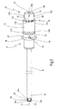
Fig. 1 ist ein mit dem allgemeinen Bezugszeichen 10 versehenes medizinisches Instrument zum Schneiden von Gewebe dargestellt. Weitere Einzelheiten des medizinischen Instruments 10 sind inFig. 2 bis 6 dargestellt. - Das medizinische Instrument 10 wird bspw. in der minimal-invasiven Chirurgie zum Abtragen von Gewebe in einem menschlichen oder tierischen Körper verwendet.
- Das medizinische Instrument 10 weist an seinem proximalen Ende 12 einen abnehmbaren Handgriff 14 auf, an dem distalseitig ein Außenschaft 16 angeordnet ist. Der Außenschaft 16 ist als starres Hohlrohr ausgebildet und weist an seinem distalen Ende 18 ein halbumfänglich ausgebildetes Fenster 20 auf. In dem Außenschaft 16 ist ein ebenfalls als starres Hohlrohr ausgebildeter Innenschaft 22 aufgenommen, der um eine Längsachse 24 des medizinischen Instruments 10 drehbar ausgebildet ist. Der Innenschaft 22 weist im Bereich seines distalen Endes 26 ein Fenster 28 auf, das axial im Bereich des Fensters 20 des Außenschafts 16 angeordnet ist, so dass die Fenster 20, 28 im aufgenommenen Zustand des Innenschafts 22 etwa auf gleicher axialer Höhe liegen (vgl.
Fig. 2 ). Das Fenster 28 des Innenschafts 22 ist mit zumindest einem Schneidelement 30, hier dargestellt mit zwei Schneidelementen 30a, b, versehen, die beidseitig an parallel zur Längsachse 24 angeordneten Kanten 32a, b des Fensters 28 vorgesehen sind. - Der Innenschaft 22 ist zum Abtragen von seitlich des Außenschafts 16 befindlichem Gewebe in Rotation versetzbar, so dass die Schneidelemente 30a, b am Fenster 20 des Außenschafts 16 vorbei laufen und das Gewebe abtrennen.
- Der Außenschaft 16 und der Innenschaft 22 sind aus Edelstahl mit geeigneter Wandstärke ausgebildet, so dass beide Bauteile eine ausreichende Steifigkeit gegen beim Schneidvorgang auftretenden Torsionskräften aufweisen. Ein Durchmesser des Außenschafts liegt im Bereich von wenigen Millimetern und ist folglich derart klein ausgebildet, das der Arzt vor Einführen des distalen Endes 18 des Außenschafts 16 in den Körper nur einen keinen Schnitt in eine äußere Haut eines Patienten ausführen muss.
- Der Außenschaft 16 ist drehfest mit einem Kupplungselement 34 verbunden, über das der Außenschaft 16 mit dem Handgriff 14 verbindbar ist. Bei dem in
Fig. 1 bis 6 gezeigten medizinischen Instrument 10 ist der Außenschaft 16 mit einer inneren Oberfläche 35 einer axial verlaufenden Bohrung 36 des Kupplungselements 34 verklebt. Das Kupplungselement 34 ist über eine Steckverbindung zumindest teilweise in einer distalseitigen Öffnung 37 des Handgriffs 14 aufnehmbar. Hierzu weist das Kupplungselement 34 eine vollumlaufende ringförmige Verbreiterung 38 auf, deren proximalseitig angeordnete Oberfläche 40 in einer entsprechenden ringförmigen Vertiefung 42 des Handgriffs 14 einschiebbar ist. Das Kupplungselement 34 weist ferner eine vollumfängliche Nut 43 auf, in die eine ringförmige Verbreiterung 44 des Handgriffs 14 eingreift. Hierdurch wird eine axiale Lageverschiebung des Handgriffs 14 und des Kupplungselements 34 verhindert. Um eine drehfeste Verbindung des Kupplungselements 34 mit dem Handgriff 14 herzustellen, weist das Kupplungselement 34 ferner zumindest einen Steg 45 auf, der direkt benachbart zur Oberfläche 40 der ringförmigen Verbreiterung 38 angeordnet und in eine entsprechende Aufnahme 46 des Handgriffs 14 formschlüssig einrastbar ist. Das Kupplungselement 34 kann auch mehrere Stege 45 aufweisen, die in jeweilige Aufnahmen 46 des Handgriffs 14 einschiebbar sind. - Ein proximaler Endbereich 48 des Innenschafts 22 ist drehfest mit einem Rotationsübertragungselement 50 verbunden, indem er mit einer inneren Oberfläche 51 des Rotationsübertragungselements 50 verklebt ist. In einem aufgenommenen Zustand ist der Innenschaft 22 entlang eines in
Fig. 2 dargestellten Pfeils 52 in dem Außenschaft 16 eingebracht, so dass eine distale Stirnfläche 54 des Rotationsübertragungselements 50 an einer proximalen Stirnfläche 56 des Kupplungselements 34 anliegt. Das Rotationsübertragungselement 50 weist ferner eine vollumlaufende Nut 58 auf, in die umfänglich angeordnete Steckelemente 60 des Kupplungselements 34, inFig. 1 dargestellt zwei Steckelemente 60a, b, formschlüssig eingreifen, so dass das Rotationsübertragungselement 50 und das Kupplungselement 34 zueinander axial fest, aber frei drehbar angeordnet sind. - Das Kupplungselement 34 und das Rotationsübertragungselement 50 sind aus einem Kunststoffmaterial, bspw. PVC, gefertigt.
- Ferner sind an eine äußere Oberfläche 62 des Rotationsübertragungselements 50 Antriebsmittel (nicht dargestellt), bspw. ein Elektromotor, anbringbar, die eine Rotationsbewegung des Rotationsübertragungselements 50 relativ zum Kupplungselement 34, d. h. des Innenschafts 22 relativ zum Außenschaft 16, bewirken. Hierzu sind an der äußeren Oberfläche 62 des Rotationsübertragungselements 50 ellipsenförmige, im Wesentlichen parallel zur Längsachse 24 angeordnete Angreifelemente 63, in
Fig. 1 dargestellt zwei Angreifelemente 63a, b, vorgesehen, an denen eine Antriebswelle der Antriebsmittel angreifen. - Es ist ferner eine Saugleitung (nicht dargestellt) an einem proximalen Ende 64 des Innenschafts 22 anbringbar, die bspw. über eine Steckverbindung in das proximale Ende 64 des Innenschafts 22 eingreift. Das proximale Ende 64 des Innenschafts 22 schließt mit einer nach proximal weisenden Stirnfläche 66 des Rotationsübertragungselements 50 ab, so dass ein distales Ende der Saugleitung direkt an der Stirnfläche 66 des Rotationsübertragungselements 50 angeordnet werden kann und somit eine flüssigkeitsdichte Verbindung des Innenschafts 22 und der Saugleitung erzeugt wird.
- Das medizinische Instrument 10 weist ferner ein durch eine Rotationsbewegung des Innenschafts 22 irreversibel lösbares Fixierelement 68 auf, das in seinem ungelösten Zustand den Innenschaft 22 relativ zum Außenschaft 16 drehfest in einer vorgegebenen Stellung hält. Der Außenschaft 16 und der Innenschaft 22 können bspw. derart angeordnet sein, dass das Fenster 28 des Innenschafts 22 dem Fenster 20 des Außenschafts 16 entgegengesetzt angeordnet ist, so dass das Fenster 20 des Außenschafts 16 durch das distale Ende 26 des Innenschafts 22 verschlossen ist (vgl.
Fig. 5 ). Diese Anordnung der Fenster 20, 28 ist insbesondere im Rahmen von Eingriffen vorteilhaft, bei denen das distale Ende 18 des Außenschafts 16 in eine Körperöffnung eingeführt wird, während die Saugleitung an das Rotationsübertragungselement 50 angeschlossen und aktiviert ist. Der Innenschaft 22 kann ebenfalls bezüglich des Außenschafts 16 derart angeordnet sein, dass das Fenster 20 des Außenschafts 16 maximal geöffnet ist (vgl.Fig. 3 ). Diese Stellung beider Fenster 20, 28 kann für operative Eingriffe im Bereich der Hals-Nasen-Ohren-Heilkunde bevorzugt sein. Hierbei weisen das Fenster 20 des Außenschafts 16 und das Fenster 28 des Innenschafts 22 in eine gleiche Richtung, so dass auch beim Einführen des distalen Endes 18 des Außenschafts 16 Flüssigkeit oder Gewebe aus dem Operationsgebiet abgesaugt werden kann. Es ist ebenfalls möglich, dass der Innenschaft 22 relativ zum Außenschaft 16 in jeder möglichen Stellung drehfest gehalten wird. - In einem ersten, in
Fig. 3 ,4 dargestellten Ausführungsbeispiel weist das Fixierelement 68 zumindest einen länglichen Steg 72 aus Kunststoff, hier drei längliche Stege 72a-c, auf, die eine äußere Oberfläche 74 des Kupplungselements 34 mit der äußeren Oberfläche 62 des Rotationsübertragungselements 50 verbinden. Die Kunststoffstege 72a-c sind entlang eines Umfangs des Kupplungselements 34 und des Rotationsübertragungselements 50 in regelmäßigen Abständen, bspw. jeweils unter 45° zur Längsachse 24, angeordnet. - Das Kupplungselement 34, die Kunststoffstege 72a-c und das Rotationsübertragungselement 50 sind bei ihrer Fertigung durch Spritzgießen einstückig ausgebildet, so dass der Innenschaft 22 relativ zum Außenschaft 16 in der jeweils fertigungsbedingten vorgegebenen Stellung angeordnet ist. Die drei Bauteile können auch mittels Extrusionstechnik gefertigt sein.
- Um die Relativstellung des Außen- und Innenschafts 16, 22 zueinander auszurichten und nachträglich überprüfen zu können, weist das medizinische Instrument 10 ferner einen Positionsindikator 76 auf, der in Form eines nach proximal weisenden Pfeils 78 auf der Oberfläche 74 des Kupplungselements 34 direkt benachbart zur ringförmigen Verbreiterung 38 angeordnet ist. In den in
Fig. 3-6 dargestelltem Ausführungsbeispiel des Positionsindikators 76 entspricht dieser dem Steg 45. Bei der Herstellung des medizinischen Instruments 10 wird darauf geachtet, dass der Kunststoffsteg 72b in Flucht mit bspw. einer Spitze 79 des Pfeils 78 angeordnet ist, so dass, wie inFig. 3 dargestellt, das Fenster 20 des Außenschafts 16 geöffnet ist. Hierbei kann der Kunststoffsteg 72b zusätzlich farblich besonders gekennzeichnet sein und/oder es kann zusätzlich eine ebenfalls in Flucht mit dem Positionsindikator 76 angeordnete Markierung auf der äußeren Oberfläche 62 des Rotationsübertragungselements 50 vorgesehen sein, so dass die relative Anordnung des Außen- und Innenschafts 16, 22 einfach eingestellt und überprüft werden kann. - Der Positionsindikator 76 kann ebenfalls auf einem Bereich der äußeren Oberfläche 62 des Rotationsübertragungselements 50 aufgebracht sein, der bspw. dann sichtbar ist, wenn das Kupplungselement 34 noch nicht im Handgriff 14 aufgenommen ist. Der Positionsindikator 76 kann anstelle des nach proximal weisenden Pfeils 78 als nach distal weisender Pfeil oder als kleiner, farblich zum Kupplungselement 34 und Rotationsübertragungselement 50 unterscheidbarer Punkt ausgebildet sein.
- Wenn die Schneidelemente 30a, b bspw. nach Einführen des distalen Endes 18 des Außenschafts 16 in die Körperöffnung in Betrieb genommen wird, verursachen die Antriebsmittel eine Rotationsbewegung des Rotationsübertragungselement 50 in Richtung eines in
Fig. 4 und6 dargestellten Pfeils 80, die auf den Innenschaft 22 übertragen wird. Der Außenschaft 16 verleibt in seiner Stellung und rotiert nicht um die Längsachse 24. Es ist ebenfalls möglich, dass der Innenschaft 22 entgegengesetzt zu der durch den Pfeil 80 angedeuteten Rotationsrichtung rotiert. - Die Rotationsbewegung des Innenschafts 22 erzeugt Torsions- und Scherkräfte auf die Kunststoffstege 72a-c, die bei genügend großer Krafteinwirkung an einer Sollbruchstelle zerbrechen, wodurch die drehfeste Anordnung des Außen- und Innenschafts 16, 22 irreversibel gelöst ist. Wie in
Fig. 4 dargestellt, ist der Kunststoffsteg 72b an seinem proximalen Ende 82 von der Oberfläche 62 des Rotationsübertragungselements 50 abgebrochen, so dass er nur noch an der äußeren Oberfläche 74 des Kupplungselements 34 befestigt ist. - Die Stege 72a-c können ferner bspw. in ihrem Mittelbereich eine Perforierung aufweisen, um ihr Brechen in diesem definierten Bereich zu unterstützen. Diese Perforierung wirkt hierbei als Sollbruchstelle des Fixierelements 68.
- Das medizinische Instrument 10 ist aufgrund des irreversibel lösbaren Fixierelements 68 insbesondere als Einweginstrument geeignet.
- In einem in
Fig. 5 dargestellten, weiteren Ausführungsbeispiel ist das Fixierelement 68 als vollumfänglicher Kunststoffring 84 ausgebildet, der über kleine Kunststoffbrücken 86, hier dargestellt sieben Kunststoffbrücken 86a-g, mit einer proximalseitigen Stirnfläche 88 des Kupplungselements 34 verbunden ist. Der Kunststoffring 84, die Kunststoffbrücken 86a-g und das Kupplungselement 34 sind einstückig spritzgegossen. - Der Kunststoffring 84 sitzt reibschlüssig auf der äußeren Oberfläche 62 des Rotationsübertragungselements 50 auf, so dass das Rotationsübertragungselement 50 und das Kupplungselement 34 in einem Ruhezustand drehfest zueinander angeordnet sind. Hierdurch ist der Innenschaft 22 und der Außenschaft 16 in einer solchen Stellung angeordnet, bei der, wie in
Fig. 5 dargestellt, das distale Ende 26 des Innenschafts 22 das Fenster 20 des Außenschafts 16 verschließt. Der Positionsindikator 76 ist in Flucht mit einem durch seine Farbgebung besonders markierten Bereich 90 des Kunststoffrings 84, hier dargestellt mit einem farbigen Punkt 92, angeordnet. - Wie in
Fig. 6 dargestellt, bewirkt die Rotationsbewegung des Innenschafts 22 entlang des Pfeils 80 eine Verdrehung des Rotationsübertragungselements 50 relativ zum Kupplungselement 34, so dass Torsions- und Scherkräfte an den Kunststoffbrücken 86a-g angreifen. Der Ring 84 bricht unter dieser Krafteinwirkung entlang der Kunststoffbrücken 86a-g vom Kupplungselement 34 ab, die eine Sollbruchlinie des Fixierelements 68 definieren. Der vom Kupplungselement 34 abgetrennte Kunststoffring 84 verbleibt während der restlichen Zeit des operativen Eingriffs in dieser Position. - Es ist ebenfalls möglich, dass das Fixierelement 68 aus biegeflexiblen, reißfähigen Material, bspw. Gummi, ausgebildet ist, das zwischen der äußeren Oberfläche 62 des Rotationsübertragungselements 50 und einer inneren Oberfläche 94 des Kupplungselements 34 angeordnet ist. Durch ein bei der Rotationsbewegung auftretendes Drehmoment reißt das Gummi und löst den Innenschaft 22 irreversibel vom Außenschaft 16.
Claims (11)
- Medizinisches Instrument zum Schneiden von Gewebe, mit einem rohrförmigen Außenschaft (16), der im Bereich seines distalen Endes (18) zumindest ein Fenster (20) aufweist, mit einem rohrförmigen, um eine Längsachse (24) rotierbaren, in dem Außenschaft (16) aufgenommenen Innenschaft (22), der an seinem distalen Ende (26) ein im Bereich des zumindest einen Fensters (20) des Außenschafts (16) angeordnetes und mit zumindest einem Schneidelement (30a, b) versehenes Fenster (28) aufweist, gekennzeichnet durch ein Fixierelement (68) zum drehfesten Halten des Innenschafts (22) relativ zum Außenschaft (16) in einer vorgegebenen Stellung, wobei das Fixierelement (68) durch eine Rotationsbewegung des Innenschafts (22) irreversibel lösbar ist.
- Medizinisches Instrument nach Anspruch 1, dadurch gekennzeichnet, dass das Fixierelement (68) ein mit dem Außenschaft (16) drehfest verbundenes Kupplungselement (34) zum Verbinden des Außenschafts (16) mit einem Handgriff (14) mit einem mit dem Innenschaft (22) drehfest verbundenen Rotationsübertragungselement (50) zum Verbinden des Innenschafts (22) mit Antriebsmitteln verbindet.
- Medizinisches Instrument nach Anspruch 2, dadurch gekennzeichnet, dass das Fixierelement (68) an einer äußeren Oberfläche (74, 62) des Kupplungselements (34) und des Rotationsübertragungselements (50) angeordnet ist.
- Medizinisches Instrument nach Anspruch 2 oder 3, dadurch gekennzeichnet, dass das Fixierelement (68) zumindest teilweise umfänglich am Kupplungselement (34) und/oder Rotationsübertragungselement (50) angeordnet ist.
- Medizinisches Instrument nach einem der Ansprüche 2 bis 4, dadurch gekennzeichnet, dass das Kupplungselement (34) und das Fixierelement (68) einstückig ausgebildet sind.
- Medizinisches Instrument nach einem der Ansprüche 2 bis 5, dadurch gekennzeichnet, dass das Rotationsübertragungselement (50) und das Fixierelement (68) einstückig ausgebildet sind.
- Medizinisches Instrument nach einem der Ansprüche 1 bis 6, dadurch gekennzeichnet, dass das Fixierelement (68) zumindest einen länglichen Steg (72a-c) aufweist, der durch die Rotationsbewegung des Innenschafts (22) an zumindest einer Sollbruchstelle bricht.
- Medizinisches Instrument nach Anspruch 7, dadurch gekennzeichnet, dass der zumindest eine Steg (72a-c) entlang der Längsachse (24) angeordnet ist.
- Medizinisches Instrument nach einem der Ansprüche 1 bis 6, dadurch gekennzeichnet, dass das Fixierelement (68) einen Ring (84) aufweist, der durch die Rotationsbewegung des Innenschafts (22) entlang einer Sollbruchlinie bricht.
- Medizinisches Instrument nach einem der Anspruch 1 bis 9, gekennzeichnet durch einen Positionsindikator (76) zum Ausrichten des Innenschafts (22) relativ zum Außenschaft (16) in der vorgegebenen Stellung, wobei der Positionsindikator (76) in einer Flucht mit dem Fixierelement (68) angeordnet ist.
- Medizinisches Instrument nach Anspruch 10, dadurch gekennzeichnet, dass der Positionsindikator (76) an der äußeren Oberfläche (74) des Kupplungselements (34) angeordnet ist.
Applications Claiming Priority (1)
| Application Number | Priority Date | Filing Date | Title |
|---|---|---|---|
| DE102007006276A DE102007006276A1 (de) | 2007-01-31 | 2007-01-31 | Medizinisches Instrument zum Schneiden von Gewebe |
Publications (3)
| Publication Number | Publication Date |
|---|---|
| EP1952773A2 true EP1952773A2 (de) | 2008-08-06 |
| EP1952773A3 EP1952773A3 (de) | 2010-04-28 |
| EP1952773B1 EP1952773B1 (de) | 2011-05-04 |
Family
ID=39420326
Family Applications (1)
| Application Number | Title | Priority Date | Filing Date |
|---|---|---|---|
| EP08001608A Not-in-force EP1952773B1 (de) | 2007-01-31 | 2008-01-29 | Medizinisches Instrument zum Schneiden von Gewebe |
Country Status (4)
| Country | Link |
|---|---|
| US (1) | US8088136B2 (de) |
| EP (1) | EP1952773B1 (de) |
| AT (1) | ATE507782T1 (de) |
| DE (2) | DE102007006276A1 (de) |
Cited By (1)
| Publication number | Priority date | Publication date | Assignee | Title |
|---|---|---|---|---|
| CN108366808A (zh) * | 2015-10-14 | 2018-08-03 | 科林斯医疗科技公司 | 手术装置和使用方法 |
Families Citing this family (15)
| Publication number | Priority date | Publication date | Assignee | Title |
|---|---|---|---|---|
| USD597204S1 (en) * | 2007-05-09 | 2009-07-28 | Karl Storz Gmbh & Co. Kg | Medical instrument |
| USD624653S1 (en) * | 2008-03-20 | 2010-09-28 | Bien-Air Holding Sa | Chirurgical lame shaver |
| TWD134208S1 (zh) * | 2009-07-01 | 2010-04-01 | 賴銘曉 | 採血筆 |
| US20110087254A1 (en) * | 2009-10-09 | 2011-04-14 | Cardiovascular Systems, Inc. | Rotational atherectomy device with keyed exchangeable drive shaft |
| US8574254B2 (en) | 2011-01-25 | 2013-11-05 | Smith & Nephew, Inc. | Arthroscopic cutting blade |
| US9204868B2 (en) | 2011-12-02 | 2015-12-08 | Interscope, Inc. | Methods and apparatus for removing material from within a mammalian cavity using an insertable endoscopic instrument |
| US9808146B2 (en) * | 2011-12-02 | 2017-11-07 | Interscope, Inc. | Endoscopic tool for debriding and removing polyps |
| US11076840B2 (en) | 2011-12-02 | 2021-08-03 | Interscope, Inc. | Surgical console, specimen receiver, and insertable endoscopic instrument for tissue removal |
| US8882680B2 (en) | 2011-12-02 | 2014-11-11 | Interscope, Inc. | Insertable endoscopic instrument for tissue removal |
| USD855802S1 (en) | 2011-12-23 | 2019-08-06 | Interscope, Inc. | Disposable tool |
| EP2904981B1 (de) * | 2012-10-05 | 2017-05-10 | Olympus Corporation | Behandlungsgerät |
| US10286126B2 (en) * | 2012-11-06 | 2019-05-14 | University of Pittsburgh—of the Commonwealth System of Higher Education | Adjustable liposuction cannula |
| EP3038549B1 (de) | 2013-09-27 | 2019-08-07 | Release Medical, Inc. | Vorrichtung für gewebeeinschnitte |
| US20150141809A1 (en) * | 2013-11-20 | 2015-05-21 | Covidien Lp | Devices, systems, and methods for navigating a biopsy tool to a target location and obtaining a tissue sample using the same |
| US11622786B2 (en) * | 2019-03-27 | 2023-04-11 | Gyrus Acmi, Inc. | Planar alignment for asymmetric cutting members |
Citations (1)
| Publication number | Priority date | Publication date | Assignee | Title |
|---|---|---|---|---|
| US5492527A (en) | 1994-09-09 | 1996-02-20 | Linvatec Corporation | Arthroscopic shaver with rotatable collet and slide aspiration control valve |
Family Cites Families (21)
| Publication number | Priority date | Publication date | Assignee | Title |
|---|---|---|---|---|
| DE2637747A1 (de) * | 1976-08-21 | 1978-02-23 | Wolf Gmbh Richard | Resektoskop mit spuelwasserzu- und -ablauf |
| US4508534A (en) * | 1981-12-02 | 1985-04-02 | Baxter Travenol Laboratories, Inc. | Assembly employing a breakable thermal bond which is not substantially effected by prolonged heat exposure |
| US4685472A (en) * | 1984-01-23 | 1987-08-11 | Rudolph Muto | Specimen collector |
| US4667837A (en) * | 1986-06-05 | 1987-05-26 | International Medical Industries, Incorporated | Tamper proof cap |
| US4815462A (en) * | 1987-04-06 | 1989-03-28 | Clark Vickie J | Lipectomy device |
| DE4101472C2 (de) * | 1991-01-19 | 1995-07-13 | Winter & Ibe Olympus | Endoskop zur transurethralen Resektion |
| US5672945A (en) * | 1992-04-13 | 1997-09-30 | Smith & Nephew Endoscopy, Inc. | Motor controlled surgical system and method having self clearing motor control |
| US5282821A (en) * | 1993-01-26 | 1994-02-01 | Donahue John R | Adjustable surgical instrument |
| US5364395A (en) * | 1993-05-14 | 1994-11-15 | West Jr Hugh S | Arthroscopic surgical instrument with cauterizing capability |
| US5665101A (en) * | 1996-04-01 | 1997-09-09 | Linvatec Corporation | Endoscopic or open lipectomy instrument |
| US5741287A (en) * | 1996-11-01 | 1998-04-21 | Femrx, Inc. | Surgical tubular cutter having a tapering cutting chamber |
| US20050011855A1 (en) * | 2002-04-11 | 2005-01-20 | Zapata Felipe Lopez | Tamper-proof cap for bottles |
| US6958071B2 (en) * | 2002-07-13 | 2005-10-25 | Stryker Corporation | Surgical tool system |
| US20040147909A1 (en) * | 2002-12-20 | 2004-07-29 | Gyrus Ent L.L.C. | Surgical instrument |
| US7150747B1 (en) * | 2003-01-22 | 2006-12-19 | Smith & Nephew, Inc. | Electrosurgical cutter |
| US7276074B2 (en) * | 2004-01-21 | 2007-10-02 | Medtronic Xomed, Inc. | Angled tissue cutting instrument having variably positionable cutting window, indexing tool for use therewith and method of variably positioning a cutting window of an angled tissue cutting instrument |
| US7226460B2 (en) * | 2004-08-02 | 2007-06-05 | Karl Storz Endovision, Inc. | Surgical instrument attachment system |
| US20060212060A1 (en) * | 2005-02-11 | 2006-09-21 | Arthrex, Inc. | Arthroscopic shaver and method of manufacturing same |
| US7988670B2 (en) * | 2005-06-30 | 2011-08-02 | Tyco Healthcare Group Lp | Trocar assembly with rotatable obturator housing |
| US8403977B2 (en) * | 2006-05-04 | 2013-03-26 | Cook Medical Technologies Llc | Self-orienting delivery system |
| US7967821B2 (en) * | 2006-11-20 | 2011-06-28 | Depuy Spine, Inc. | Break-off screw extension removal tools |
-
2007
- 2007-01-31 DE DE102007006276A patent/DE102007006276A1/de not_active Withdrawn
-
2008
- 2008-01-29 AT AT08001608T patent/ATE507782T1/de active
- 2008-01-29 EP EP08001608A patent/EP1952773B1/de not_active Not-in-force
- 2008-01-29 DE DE502008003390T patent/DE502008003390D1/de active Active
- 2008-01-31 US US12/023,453 patent/US8088136B2/en not_active Expired - Fee Related
Patent Citations (1)
| Publication number | Priority date | Publication date | Assignee | Title |
|---|---|---|---|---|
| US5492527A (en) | 1994-09-09 | 1996-02-20 | Linvatec Corporation | Arthroscopic shaver with rotatable collet and slide aspiration control valve |
Cited By (1)
| Publication number | Priority date | Publication date | Assignee | Title |
|---|---|---|---|---|
| CN108366808A (zh) * | 2015-10-14 | 2018-08-03 | 科林斯医疗科技公司 | 手术装置和使用方法 |
Also Published As
| Publication number | Publication date |
|---|---|
| DE502008003390D1 (de) | 2011-06-16 |
| US20080183201A1 (en) | 2008-07-31 |
| EP1952773A3 (de) | 2010-04-28 |
| US8088136B2 (en) | 2012-01-03 |
| EP1952773B1 (de) | 2011-05-04 |
| DE102007006276A1 (de) | 2008-08-07 |
| ATE507782T1 (de) | 2011-05-15 |
Similar Documents
| Publication | Publication Date | Title |
|---|---|---|
| EP1952773B1 (de) | Medizinisches Instrument zum Schneiden von Gewebe | |
| EP2305145B1 (de) | Zerlegbares medizinisches Zangensystem | |
| EP1587419B1 (de) | Medizinische baugruppe sowie eine schutzvorrichtung, ein einstichelement und eine handhabungsvorrichtung für diese baugruppe | |
| DE60318543T2 (de) | Handgriffanordnung für eine Biopsievorrichtung | |
| EP1269925B1 (de) | Zugangskanüle für endoskopische Operationen, insbesondere für die Arthroskopie | |
| DD233302A1 (de) | Sicherheitsbiopsiezange | |
| DE102005044364A1 (de) | Abstandhalter für ein medizinisches Instrument | |
| DE3045005A1 (de) | Venenpunktionsvorrichtung | |
| EP1601293B1 (de) | Medizinisches instrumentarium zum schaffen eines operativen arbeitsraumes bei kieferoperationen | |
| CH687501A5 (de) | Chirurgisches Handstueck. | |
| WO2011076364A1 (de) | Chirurgisches instrument zur lösbaren verbindung eines handstückes mit einem chirurgischen werkzeug | |
| EP2575629A1 (de) | Gelenk-biopsienadel zur entnahme von gewebeproben | |
| WO1992012676A2 (de) | Zervix-stanze | |
| DE102007034577A1 (de) | Medizinisches Instrument | |
| WO2007031264A1 (de) | Medizinisches instrument | |
| EP2877098B1 (de) | Halter für ein medizinisches, insbesondere chirurgisches instrument | |
| WO2010118831A1 (de) | Zerlegbares chirurgisches instrument | |
| EP1924313B8 (de) | Medizinisches instrument | |
| EP2395926B1 (de) | Chirurgische klammereinrichtung | |
| EP1587434A1 (de) | Medizinisches instrument zum präparieren von gewebe | |
| DE102007031799B3 (de) | Kanülenvorrichtung zur Entnahme von Rückenmarksflüssigkeiten (Liquor) | |
| DE10032007A1 (de) | Schneidinstrument für die Entnahme von Gewebeproben, insbesondere von Glaskörperchen | |
| DE202007005357U1 (de) | Trokar und Einführhilfe für einen Trokar | |
| DE20110491U1 (de) | Zugangskanüle für endoskopische Operationen, insbesondere für die Arthroskopie | |
| DE102022002849A1 (de) | Proktoskop und Verfahren zum Einsatz eines Proktoskops |
Legal Events
| Date | Code | Title | Description |
|---|---|---|---|
| PUAI | Public reference made under article 153(3) epc to a published international application that has entered the european phase |
Free format text: ORIGINAL CODE: 0009012 |
|
| AK | Designated contracting states |
Kind code of ref document: A2 Designated state(s): AT BE BG CH CY CZ DE DK EE ES FI FR GB GR HR HU IE IS IT LI LT LU LV MC MT NL NO PL PT RO SE SI SK TR |
|
| AX | Request for extension of the european patent |
Extension state: AL BA MK RS |
|
| PUAL | Search report despatched |
Free format text: ORIGINAL CODE: 0009013 |
|
| AK | Designated contracting states |
Kind code of ref document: A3 Designated state(s): AT BE BG CH CY CZ DE DK EE ES FI FR GB GR HR HU IE IS IT LI LT LU LV MC MT NL NO PL PT RO SE SI SK TR |
|
| AX | Request for extension of the european patent |
Extension state: AL BA MK RS |
|
| 17P | Request for examination filed |
Effective date: 20101002 |
|
| GRAP | Despatch of communication of intention to grant a patent |
Free format text: ORIGINAL CODE: EPIDOSNIGR1 |
|
| RIC1 | Information provided on ipc code assigned before grant |
Ipc: A61B 17/32 20060101AFI20101028BHEP Ipc: A61B 17/28 20060101ALI20101028BHEP |
|
| AKX | Designation fees paid |
Designated state(s): AT BE BG CH CY CZ DE DK EE ES FI FR GB GR HR HU IE IS IT LI LT LU LV MC MT NL NO PL PT RO SE SI SK TR |
|
| GRAS | Grant fee paid |
Free format text: ORIGINAL CODE: EPIDOSNIGR3 |
|
| GRAA | (expected) grant |
Free format text: ORIGINAL CODE: 0009210 |
|
| AK | Designated contracting states |
Kind code of ref document: B1 Designated state(s): AT BE BG CH CY CZ DE DK EE ES FI FR GB GR HR HU IE IS IT LI LT LU LV MC MT NL NO PL PT RO SE SI SK TR |
|
| REG | Reference to a national code |
Ref country code: GB Ref legal event code: FG4D Free format text: NOT ENGLISH |
|
| REG | Reference to a national code |
Ref country code: CH Ref legal event code: EP |
|
| REG | Reference to a national code |
Ref country code: IE Ref legal event code: FG4D Free format text: LANGUAGE OF EP DOCUMENT: GERMAN |
|
| REF | Corresponds to: |
Ref document number: 502008003390 Country of ref document: DE Date of ref document: 20110616 Kind code of ref document: P |
|
| REG | Reference to a national code |
Ref country code: DE Ref legal event code: R096 Ref document number: 502008003390 Country of ref document: DE Effective date: 20110616 |
|
| REG | Reference to a national code |
Ref country code: NL Ref legal event code: VDEP Effective date: 20110504 |
|
| PG25 | Lapsed in a contracting state [announced via postgrant information from national office to epo] |
Ref country code: PT Free format text: LAPSE BECAUSE OF FAILURE TO SUBMIT A TRANSLATION OF THE DESCRIPTION OR TO PAY THE FEE WITHIN THE PRESCRIBED TIME-LIMIT Effective date: 20110905 Ref country code: NO Free format text: LAPSE BECAUSE OF FAILURE TO SUBMIT A TRANSLATION OF THE DESCRIPTION OR TO PAY THE FEE WITHIN THE PRESCRIBED TIME-LIMIT Effective date: 20110804 Ref country code: LT Free format text: LAPSE BECAUSE OF FAILURE TO SUBMIT A TRANSLATION OF THE DESCRIPTION OR TO PAY THE FEE WITHIN THE PRESCRIBED TIME-LIMIT Effective date: 20110504 Ref country code: SE Free format text: LAPSE BECAUSE OF FAILURE TO SUBMIT A TRANSLATION OF THE DESCRIPTION OR TO PAY THE FEE WITHIN THE PRESCRIBED TIME-LIMIT Effective date: 20110504 |
|
| PG25 | Lapsed in a contracting state [announced via postgrant information from national office to epo] |
Ref country code: LV Free format text: LAPSE BECAUSE OF FAILURE TO SUBMIT A TRANSLATION OF THE DESCRIPTION OR TO PAY THE FEE WITHIN THE PRESCRIBED TIME-LIMIT Effective date: 20110504 Ref country code: FI Free format text: LAPSE BECAUSE OF FAILURE TO SUBMIT A TRANSLATION OF THE DESCRIPTION OR TO PAY THE FEE WITHIN THE PRESCRIBED TIME-LIMIT Effective date: 20110504 Ref country code: CY Free format text: LAPSE BECAUSE OF FAILURE TO SUBMIT A TRANSLATION OF THE DESCRIPTION OR TO PAY THE FEE WITHIN THE PRESCRIBED TIME-LIMIT Effective date: 20110504 Ref country code: SI Free format text: LAPSE BECAUSE OF FAILURE TO SUBMIT A TRANSLATION OF THE DESCRIPTION OR TO PAY THE FEE WITHIN THE PRESCRIBED TIME-LIMIT Effective date: 20110504 Ref country code: ES Free format text: LAPSE BECAUSE OF FAILURE TO SUBMIT A TRANSLATION OF THE DESCRIPTION OR TO PAY THE FEE WITHIN THE PRESCRIBED TIME-LIMIT Effective date: 20110815 Ref country code: GR Free format text: LAPSE BECAUSE OF FAILURE TO SUBMIT A TRANSLATION OF THE DESCRIPTION OR TO PAY THE FEE WITHIN THE PRESCRIBED TIME-LIMIT Effective date: 20110805 Ref country code: IS Free format text: LAPSE BECAUSE OF FAILURE TO SUBMIT A TRANSLATION OF THE DESCRIPTION OR TO PAY THE FEE WITHIN THE PRESCRIBED TIME-LIMIT Effective date: 20110904 |
|
| REG | Reference to a national code |
Ref country code: IE Ref legal event code: FD4D |
|
| PG25 | Lapsed in a contracting state [announced via postgrant information from national office to epo] |
Ref country code: NL Free format text: LAPSE BECAUSE OF FAILURE TO SUBMIT A TRANSLATION OF THE DESCRIPTION OR TO PAY THE FEE WITHIN THE PRESCRIBED TIME-LIMIT Effective date: 20110504 |
|
| PG25 | Lapsed in a contracting state [announced via postgrant information from national office to epo] |
Ref country code: CZ Free format text: LAPSE BECAUSE OF FAILURE TO SUBMIT A TRANSLATION OF THE DESCRIPTION OR TO PAY THE FEE WITHIN THE PRESCRIBED TIME-LIMIT Effective date: 20110504 Ref country code: IE Free format text: LAPSE BECAUSE OF FAILURE TO SUBMIT A TRANSLATION OF THE DESCRIPTION OR TO PAY THE FEE WITHIN THE PRESCRIBED TIME-LIMIT Effective date: 20110504 Ref country code: EE Free format text: LAPSE BECAUSE OF FAILURE TO SUBMIT A TRANSLATION OF THE DESCRIPTION OR TO PAY THE FEE WITHIN THE PRESCRIBED TIME-LIMIT Effective date: 20110504 |
|
| PG25 | Lapsed in a contracting state [announced via postgrant information from national office to epo] |
Ref country code: SK Free format text: LAPSE BECAUSE OF FAILURE TO SUBMIT A TRANSLATION OF THE DESCRIPTION OR TO PAY THE FEE WITHIN THE PRESCRIBED TIME-LIMIT Effective date: 20110504 Ref country code: DK Free format text: LAPSE BECAUSE OF FAILURE TO SUBMIT A TRANSLATION OF THE DESCRIPTION OR TO PAY THE FEE WITHIN THE PRESCRIBED TIME-LIMIT Effective date: 20110504 Ref country code: RO Free format text: LAPSE BECAUSE OF FAILURE TO SUBMIT A TRANSLATION OF THE DESCRIPTION OR TO PAY THE FEE WITHIN THE PRESCRIBED TIME-LIMIT Effective date: 20110504 Ref country code: PL Free format text: LAPSE BECAUSE OF FAILURE TO SUBMIT A TRANSLATION OF THE DESCRIPTION OR TO PAY THE FEE WITHIN THE PRESCRIBED TIME-LIMIT Effective date: 20110504 |
|
| PLBE | No opposition filed within time limit |
Free format text: ORIGINAL CODE: 0009261 |
|
| STAA | Information on the status of an ep patent application or granted ep patent |
Free format text: STATUS: NO OPPOSITION FILED WITHIN TIME LIMIT |
|
| 26N | No opposition filed |
Effective date: 20120207 |
|
| PG25 | Lapsed in a contracting state [announced via postgrant information from national office to epo] |
Ref country code: HR Free format text: LAPSE BECAUSE OF FAILURE TO SUBMIT A TRANSLATION OF THE DESCRIPTION OR TO PAY THE FEE WITHIN THE PRESCRIBED TIME-LIMIT Effective date: 20111123 |
|
| REG | Reference to a national code |
Ref country code: DE Ref legal event code: R097 Ref document number: 502008003390 Country of ref document: DE Effective date: 20120207 |
|
| BERE | Be: lapsed |
Owner name: KARL STORZ G.M.B.H. & CO. KG Effective date: 20120131 |
|
| PG25 | Lapsed in a contracting state [announced via postgrant information from national office to epo] |
Ref country code: MC Free format text: LAPSE BECAUSE OF NON-PAYMENT OF DUE FEES Effective date: 20120131 |
|
| REG | Reference to a national code |
Ref country code: CH Ref legal event code: PL |
|
| PG25 | Lapsed in a contracting state [announced via postgrant information from national office to epo] |
Ref country code: LI Free format text: LAPSE BECAUSE OF NON-PAYMENT OF DUE FEES Effective date: 20120131 Ref country code: CH Free format text: LAPSE BECAUSE OF NON-PAYMENT OF DUE FEES Effective date: 20120131 |
|
| PG25 | Lapsed in a contracting state [announced via postgrant information from national office to epo] |
Ref country code: BE Free format text: LAPSE BECAUSE OF NON-PAYMENT OF DUE FEES Effective date: 20120131 |
|
| PG25 | Lapsed in a contracting state [announced via postgrant information from national office to epo] |
Ref country code: BG Free format text: LAPSE BECAUSE OF FAILURE TO SUBMIT A TRANSLATION OF THE DESCRIPTION OR TO PAY THE FEE WITHIN THE PRESCRIBED TIME-LIMIT Effective date: 20110804 |
|
| PG25 | Lapsed in a contracting state [announced via postgrant information from national office to epo] |
Ref country code: MT Free format text: LAPSE BECAUSE OF FAILURE TO SUBMIT A TRANSLATION OF THE DESCRIPTION OR TO PAY THE FEE WITHIN THE PRESCRIBED TIME-LIMIT Effective date: 20110504 |
|
| PG25 | Lapsed in a contracting state [announced via postgrant information from national office to epo] |
Ref country code: HR Free format text: LAPSE BECAUSE OF FAILURE TO SUBMIT A TRANSLATION OF THE DESCRIPTION OR TO PAY THE FEE WITHIN THE PRESCRIBED TIME-LIMIT Effective date: 20110504 |
|
| REG | Reference to a national code |
Ref country code: AT Ref legal event code: MM01 Ref document number: 507782 Country of ref document: AT Kind code of ref document: T Effective date: 20130129 |
|
| PG25 | Lapsed in a contracting state [announced via postgrant information from national office to epo] |
Ref country code: TR Free format text: LAPSE BECAUSE OF FAILURE TO SUBMIT A TRANSLATION OF THE DESCRIPTION OR TO PAY THE FEE WITHIN THE PRESCRIBED TIME-LIMIT Effective date: 20110504 |
|
| PG25 | Lapsed in a contracting state [announced via postgrant information from national office to epo] |
Ref country code: LU Free format text: LAPSE BECAUSE OF NON-PAYMENT OF DUE FEES Effective date: 20120129 Ref country code: AT Free format text: LAPSE BECAUSE OF NON-PAYMENT OF DUE FEES Effective date: 20130129 |
|
| PG25 | Lapsed in a contracting state [announced via postgrant information from national office to epo] |
Ref country code: HU Free format text: LAPSE BECAUSE OF FAILURE TO SUBMIT A TRANSLATION OF THE DESCRIPTION OR TO PAY THE FEE WITHIN THE PRESCRIBED TIME-LIMIT Effective date: 20080129 |
|
| REG | Reference to a national code |
Ref country code: FR Ref legal event code: PLFP Year of fee payment: 9 |
|
| PGFP | Annual fee paid to national office [announced via postgrant information from national office to epo] |
Ref country code: IT Payment date: 20160111 Year of fee payment: 9 |
|
| REG | Reference to a national code |
Ref country code: FR Ref legal event code: PLFP Year of fee payment: 10 |
|
| PGFP | Annual fee paid to national office [announced via postgrant information from national office to epo] |
Ref country code: GB Payment date: 20161228 Year of fee payment: 10 |
|
| PGFP | Annual fee paid to national office [announced via postgrant information from national office to epo] |
Ref country code: FR Payment date: 20161221 Year of fee payment: 10 |
|
| REG | Reference to a national code |
Ref country code: DE Ref legal event code: R081 Ref document number: 502008003390 Country of ref document: DE Owner name: KARL STORZ SE & CO. KG INTELLECTUAL PROPERTY, DE Free format text: FORMER OWNER: KARL STORZ GMBH & CO. KG, 78532 TUTTLINGEN, DE Ref country code: DE Ref legal event code: R082 Ref document number: 502008003390 Country of ref document: DE Representative=s name: WITTE, WELLER & PARTNER PATENTANWAELTE MBB, DE Ref country code: DE Ref legal event code: R081 Ref document number: 502008003390 Country of ref document: DE Owner name: KARL STORZ SE & CO. KG, DE Free format text: FORMER OWNER: KARL STORZ GMBH & CO. KG, 78532 TUTTLINGEN, DE |
|
| PG25 | Lapsed in a contracting state [announced via postgrant information from national office to epo] |
Ref country code: IT Free format text: LAPSE BECAUSE OF NON-PAYMENT OF DUE FEES Effective date: 20170129 |
|
| GBPC | Gb: european patent ceased through non-payment of renewal fee |
Effective date: 20180129 |
|
| PG25 | Lapsed in a contracting state [announced via postgrant information from national office to epo] |
Ref country code: FR Free format text: LAPSE BECAUSE OF NON-PAYMENT OF DUE FEES Effective date: 20180131 |
|
| REG | Reference to a national code |
Ref country code: FR Ref legal event code: ST Effective date: 20180928 |
|
| PG25 | Lapsed in a contracting state [announced via postgrant information from national office to epo] |
Ref country code: GB Free format text: LAPSE BECAUSE OF NON-PAYMENT OF DUE FEES Effective date: 20180129 |
|
| P01 | Opt-out of the competence of the unified patent court (upc) registered |
Effective date: 20230527 |
|
| PGFP | Annual fee paid to national office [announced via postgrant information from national office to epo] |
Ref country code: DE Payment date: 20231219 Year of fee payment: 17 |
|
| REG | Reference to a national code |
Ref country code: DE Ref legal event code: R119 Ref document number: 502008003390 Country of ref document: DE |
|
| PG25 | Lapsed in a contracting state [announced via postgrant information from national office to epo] |
Ref country code: DE Free format text: LAPSE BECAUSE OF NON-PAYMENT OF DUE FEES Effective date: 20250801 |