EP1952943A2 - Appareil de traitement de l'objectif à loupe - Google Patents
Appareil de traitement de l'objectif à loupe Download PDFInfo
- Publication number
- EP1952943A2 EP1952943A2 EP08001727A EP08001727A EP1952943A2 EP 1952943 A2 EP1952943 A2 EP 1952943A2 EP 08001727 A EP08001727 A EP 08001727A EP 08001727 A EP08001727 A EP 08001727A EP 1952943 A2 EP1952943 A2 EP 1952943A2
- Authority
- EP
- European Patent Office
- Prior art keywords
- lens
- hole
- front surface
- hole position
- angle
- Prior art date
- Legal status (The legal status is an assumption and is not a legal conclusion. Google has not performed a legal analysis and makes no representation as to the accuracy of the status listed.)
- Withdrawn
Links
- 238000012545 processing Methods 0.000 title claims description 45
- 238000005553 drilling Methods 0.000 claims abstract description 71
- 238000010586 diagram Methods 0.000 claims description 17
- 238000000034 method Methods 0.000 description 12
- 230000002093 peripheral effect Effects 0.000 description 9
- 238000005259 measurement Methods 0.000 description 7
- 238000005498 polishing Methods 0.000 description 3
- 238000010276 construction Methods 0.000 description 2
- 238000012937 correction Methods 0.000 description 2
- 230000000881 depressing effect Effects 0.000 description 2
- 230000000994 depressogenic effect Effects 0.000 description 2
- 238000013461 design Methods 0.000 description 2
- 230000001179 pupillary effect Effects 0.000 description 2
- XLYOFNOQVPJJNP-UHFFFAOYSA-N water Substances O XLYOFNOQVPJJNP-UHFFFAOYSA-N 0.000 description 2
- 239000002131 composite material Substances 0.000 description 1
- 239000000470 constituent Substances 0.000 description 1
- 230000006870 function Effects 0.000 description 1
- 239000011521 glass Substances 0.000 description 1
- 239000000463 material Substances 0.000 description 1
- 239000002184 metal Substances 0.000 description 1
- 230000003287 optical effect Effects 0.000 description 1
- 239000004033 plastic Substances 0.000 description 1
- 239000004417 polycarbonate Substances 0.000 description 1
- 229920000515 polycarbonate Polymers 0.000 description 1
Images


Classifications
-
- B—PERFORMING OPERATIONS; TRANSPORTING
- B24—GRINDING; POLISHING
- B24B—MACHINES, DEVICES, OR PROCESSES FOR GRINDING OR POLISHING; DRESSING OR CONDITIONING OF ABRADING SURFACES; FEEDING OF GRINDING, POLISHING, OR LAPPING AGENTS
- B24B9/00—Machines or devices designed for grinding edges or bevels on work or for removing burrs; Accessories therefor
- B24B9/02—Machines or devices designed for grinding edges or bevels on work or for removing burrs; Accessories therefor characterised by a special design with respect to properties of materials specific to articles to be ground
- B24B9/06—Machines or devices designed for grinding edges or bevels on work or for removing burrs; Accessories therefor characterised by a special design with respect to properties of materials specific to articles to be ground of non-metallic inorganic material, e.g. stone, ceramics, porcelain
- B24B9/08—Machines or devices designed for grinding edges or bevels on work or for removing burrs; Accessories therefor characterised by a special design with respect to properties of materials specific to articles to be ground of non-metallic inorganic material, e.g. stone, ceramics, porcelain of glass
- B24B9/14—Machines or devices designed for grinding edges or bevels on work or for removing burrs; Accessories therefor characterised by a special design with respect to properties of materials specific to articles to be ground of non-metallic inorganic material, e.g. stone, ceramics, porcelain of glass of optical work, e.g. lenses, prisms
- B24B9/148—Machines or devices designed for grinding edges or bevels on work or for removing burrs; Accessories therefor characterised by a special design with respect to properties of materials specific to articles to be ground of non-metallic inorganic material, e.g. stone, ceramics, porcelain of glass of optical work, e.g. lenses, prisms electrically, e.g. numerically, controlled
-
- G—PHYSICS
- G02—OPTICS
- G02C—SPECTACLES; SUNGLASSES OR GOGGLES INSOFAR AS THEY HAVE THE SAME FEATURES AS SPECTACLES; CONTACT LENSES
- G02C13/00—Assembling; Repairing; Cleaning
-
- B—PERFORMING OPERATIONS; TRANSPORTING
- B28—WORKING CEMENT, CLAY, OR STONE
- B28D—WORKING STONE OR STONE-LIKE MATERIALS
- B28D1/00—Working stone or stone-like materials, e.g. brick, concrete or glass, not provided for elsewhere; Machines, devices, tools therefor
- B28D1/14—Working stone or stone-like materials, e.g. brick, concrete or glass, not provided for elsewhere; Machines, devices, tools therefor by boring or drilling
- B28D1/143—Working stone or stone-like materials, e.g. brick, concrete or glass, not provided for elsewhere; Machines, devices, tools therefor by boring or drilling lens-drilling machines
-
- G—PHYSICS
- G02—OPTICS
- G02C—SPECTACLES; SUNGLASSES OR GOGGLES INSOFAR AS THEY HAVE THE SAME FEATURES AS SPECTACLES; CONTACT LENSES
- G02C7/00—Optical parts
- G02C7/02—Lenses; Lens systems ; Methods of designing lenses
Definitions
- the present invention relates to an eyeglass lens processing apparatus for processing a hole for attaching a rimless frame to an eyeglass lens.
- an eyeglass lens processing apparatus having a drilling tool for processing a hole for attaching a rimless frame called a "two points" frame and performs drilling by moving the drilling tool relatively to the front surface of an eyeglass lens held in a lens chuck (for example, see US-2006-0178086-A1 ( JP-A-2006-189659 ) hereinafter referred to as Patent Reference 1).
- hole position data for drilling are inputted.
- the hole position data are inputted with respect to a target lens shape seen from the lens front surface.
- the rimless frame called the "two points" frame is classified under a front fixing type in which an endpiece having a turn stopper is located on the front side of the lens (hereinafter referred to as a front fixing frame) and a rear fixing type in which the endpiece is located on the rear surface of the lens (hereinafter referred to as a rear fixing frame) (see Fig. 7 ).
- a front fixing frame by inputting the hole position data referred to the target lens shape on the lens front surface by means of the apparatus disclosed in Patent Reference 1, the hole can be easily processed.
- the invention is characterized in providing the following arrangements.
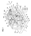
- FIG. 1 is a schematic structural view of an eyeglass lens peripheral edge processing apparatus according to the invention.
- a carriage portion 100 including a carriage 101 and a moving mechanism thereof is mounted on a base 170.
- a processed lens LE is rotated by being held (chucked) by lens chucks 102L and 102R rotatably held by the carriage 101, and is ground by a grindstone 162 constituting a processing piece attached to a grindstone spindle 161 rotated by a grindstone rotating motor 160 fixed onto the base 170.
- the grindstone 162 of the embodiment includes a roughing grindstone 162a, a bevel-finishing and flat-finishing grindstone 162b, a bevel-polishing and flat-polishing grindstone 162c, and a roughing grindstone 162d for a glass lens.
- the grindstones 162a through 162d are coaxially attached to the grindstone spindle 161.
- the lens chucks 102L and 102R are held by the carriage 101 such that center axes thereof (rotational center axis of lens LE) is in parallel with a center axis of the grindstone spindle 161 (rotational axis of grindstone 162).
- the carriage 101 is movable in a direction of the center axis of the grindstone spindle 161 (direction of center axes of lens chucks 102L and 102R) (X axis direction), and movable in a direction orthogonal to the X axis direction (direction of changing distance between center axes of lens chucks 102L and 102R and center axis of grindstone spindle 161) (Y axis direction).
- the lens chuck 102L is held by a left arm 101 L of the carriage 101 and the lens chuck 102R is held by a right arm 101 R of the carriage 101 rotatably and coaxially,
- the right arm 101 R is fixed with a lens holding (chucking) motor 110 and the lens chuck 102R is moved in a direction of the center axis by rotating the motor 110.
- the lens chuck 102R is moved in a direction of being proximate to the lens chuck 102L, and the lens LE is held (chucked) by the lens chucks 102L and 102R.
- the left arm 101 L is fixed with a lens rotating motor 120, the lens chucks 102L and 102R are rotated in synchronism with each other by rotating the motor 120 to rotate the lens LE held (chucked) thereby.
- a moving support base 140 is movably supported by guide shafts 103 and 104 fixed in parallel above the base 170 and extended in the X axis direction. Further, an X axis direction moving motor 145 is fixed above the base 170, the support base 140 is moved in the X axis direction by rotating the motor 145, and the carriage 101 supported by the guide shafts 156 and 157 fixed to the support base 140 is moved in the X axis direction.
- the carriage 101 is movably supported by the guide shafts 156 and 157 fixed in parallel to the support base 140 and extended in the Y axis direction. Further, the support base 140 is fixed with a Y axis direction moving motor 150, and the carriage 101 is moved in the Y axis direction by rotating the motor 150.
- a chamfering mechanism 200 is arranged on this side of the carriage 100.
- the chamfering mechanism 200 which is well known, will not be explained here (see, for example, JP-A-2006-239782 ).
- FIG. 1 lens edge position measuring portions (lens surface position measuring portions) 300F and 300R are arranged on the carriage 101.
- Fig. 2 is a schematic structural view for measuring of the lens measuring portion 300F for measuring the lens edge position on the lens front surface.
- An attached support base 301 F is fixed to a support base block 300a fixed on the base 170 in Fig. 1 .
- a slider 303F is slidably attached on a rail 302F fixed on the attached support base 301 F.
- a slide base 310F is attached to the slider 303F.
- a measuring piece arm 304F is fixed to the slide base 310F.
- An L-shape hand 305F is fixed to the tip of the measuring piece arm 304F, and a measuring piece 306F is fixed to the tip of the hand 305.
- the measuring piece 306F is brought into contact with the front reflecting surface of the lens LE.
- a lower end of the slide base 310F is fixed with a rack 311F.
- the rack 311F is brought in mesh with a pinion 312F of an encoder 313F fixed to the attached support base 301 F.
- Rotation of the motor 316F is transmitted to the rack 311 F by way of a gear 315F, an idle gear 314F and the pinion 312F, and slide base 310F is moved in the X axis direction. While the lens edge position is measured, the motor 316F presses the measuring piece 306F to the lens LE always by a constant force.
- the encoder 313F detects the moving position in the X-axis direction of the slide base 310F
- the edge position (inclusive of the lens front surface position) on the front surface of the lens LE is measured using the information on the moving position, the information on the rotating angle of the axes of the lens chucks 102L and 102R and their moving information in the Y-axis direction.
- the lens measuring portion 300R for measuring the edge position of a rear surface of the lens LE is symmetrical with the lens measuring portion 300F in a left and right direction, and therefore, with "R" substituted for "F” at the ends of the symbols appended to the respective constituent elements of the measuring portion 300F in Fig. 2 , an explanation of the arrangement thereof will be omitted.
- the lens edge position will be measured in such a manner that the measuring piece 306F is brought into contact with the front surface of the lens and the measuring piece 306R is brought into contact with the rear surface of the lens.
- the carriage 101 is moved in the Y axis direction on the basis of a target lens shape data, and the lens LE is rotated to thereby simultaneously measure edge data of the front surface of the lens and the rear surface of the lens for processing the lens peripheral edge.
- the measuring piece 306F and the measuring piece 306R are brought into contact with the front surface and the rear surface of the lens, respectively so that the lens front surface position and lens rear surface position at the hole position are measured.
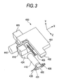
- a drilling and grooving mechanism 400 is arranged on a rear side of the carriage 100.
- Fig. 3 is a schematic structural view of the mechanism 400.
- a fixed plate 401 constituting a base of the mechanism 400 is fixed to a block (not illustrated) provided upright on the base 170 in Fig. 1 .
- the fixed support base 401 is fixed with a rail 402 extended in a Z direction (direction orthogonal to XY axes plane).
- a Z axis moving support base 404 is slidably attached along the rail 402.
- the moving support base 404 is moved in the Z axis direction by rotating a ball screw 406 by a motor 405.
- a rotating support base 410 is rotatably held by the moving support base 404.
- the rotating support base 410 is rotated around an axis thereof by a motor 416 by way of a rotation transmitting mechanism.
- the tip of the rotating support base 410 is attached with a rotating portion 430.
- a rotating shaft 431 orthogonal to an axial direction of the rotating support base 410 is rotatably held in the rotating portion 430.
- the one end of the rotating shaft 431 is coaxially attached with an end mill 435 serving as a drilling tool.
- the other end of the rotating shaft 431 is coaxially attached with a groove cutter 436 serving as a grooving piece.
- the rotating shaft 431 is rotated by a motor 440 attached to the moving support base 404 by way of a rotation transmitting mechanism arranged inside the rotating portion 430 and the rotating support base 410.
- the end mill 435 is directed to the lens front surface so that the drilling is carried out from the lens front surface side.
- the present invention is not limited to the above arrangement, and such an arrangement may be also employed that the drilling is carried out from the lens rear surface side.
- Fig. 4 is a control block diagram of an eyeglass lens peripheral edge processing apparatus.
- a control portion 50 is connected with an eyeglass frame measuring portion 2 (apparatus described in US5333412 ( JP-A-4-93164 ) can be used), a display 5 serving as a display portion and an input portion of a touch panel type, a switch portion 7, a memory 51, the carriage portion 100, the chamfering mechanism 200, the lens edge position measuring portions 300F and 300R, the drilling and grooving mechanism 400, etc.
- An input signal to the apparatus can be inputted by touching the display of the display 5 by a touch pen (or the finger).
- the control portion 50 receives the input signal by a touch panel function provided to the display 5 and controls to display diagrams and information of the display 5. Further, the control portion 50 is connected with a grinding water supply portion 53 for supplying grinding water to the processed surface of the lens when the peripheral edge of the lens LE is processed.
- a target lens shape is provided from a template or a demo lens.
- the target lens shape data provided by the eyeglass frame measuring apparatus 2 is stored in the memory 51 by depressing the switch 7.
- the display 5 is displayed with a target lens shape diagram FT to be brought into a state of capable of inputting a processing condition.
- the target lens shape of the "two points" frame which is stored beforehand in the memory 51 can be taken out from the memory 51.
- An operator is brought into a state of capable of inputting a layout data of a frame pupillary distance (FPD), a pupillary distance (PD) of the wearer, a height of a lens optical center referred to a geometrical center of the target lens shape by operating predetermined button keys 501, 502, 503 and the like (see Fig. 4 ).
- FPD frame pupillary distance
- PD pupillary distance
- a height of a lens optical center referred to a geometrical center of the target lens shape by operating predetermined button keys 501, 502, 503 and the like (see Fig. 4 ).
- the processing condition can be set by operating button keys 510, 511, 512, 513, 514.
- a material of the lens (plastic, polycarbonate or the like) is selected by the button key 510.
- Metal, cell, nylol and two points are selected as kinds of the eyeglass frame by the button key 511.
- Presence/absence of chamfering is selected by the button key 513, and in a case of presence of chamfering, a size of chamfering can be selected.
- Presence/absence of polishing can be selected by the button key 514.
- a flat processing mode is set as a mode of processing a peripheral edge of the lens and a drilling mode is set along therewith.
- data on the drilling can be inputted from a hole editing screen displayed by depressing the button key 512.
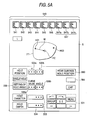
- Fig. 5A shows an example of the hole editing screen.
- the target lens shape diagram FT is displayed at the upper part on the screen of the display 5 on the basis of the inputted target lens shape data.
- holes H01 and H03 are displayed within the target lens shape diagram FT.
- Various inputting keys used for inputting the hole data are displayed at the lower part on the screen.
- a select key 560 is prepared for selecting whether the hole position data are inputted with reference to the lens front surface or the lens rear surface.
- the example of Fig. 5A illustrates the case where the hole position data are inputted with reference to the lens rear surface.
- the target lens shape diagram FT on the display 5 is displayed as the diagram when the target lens shape of a left eye lens is viewed from the lens rear surface on the basis of the select signal by the select key 560.
- a template icon group 540 is prepared at the upper part on the screen.
- the template icon group 540 is prepared in advance with a number of patterned hole types for a rimless frame.
- an icon 541 is a template of one hole (single hole) type.
- An icon 542 is a template combined with a notch and a single hole.
- An icon 543 is a template of two holes aligned in two in a horizontal direction.
- An icon 544 is a template aligned with two holes in a vertical direction.
- Icons 545, 546 are templates of long holes in the horizontal direction, and in the vertical direction, respectively.
- Icons 547a, 547b, 547c are templates of single holes having spot facing.
- data of hole diameters of through holes, hole diameters and hole depths of spot facing holes can be previously set/registered on the side of the operator, respectively.
- the operator can set the data in correspondence with the icons 547a through 547c in accordance with sizes of screws or washers utilized frequently (details thereof will be described later).
- the operator can save time and labor of inputting or changing the data of the hole diameters of the through holes, the hole diameters and the hole depths of the spot facing holes.
- the drilling is carried out by inputting the hole position data with reference to the lens front surface in order to drill the lens attached to an front-fixing frame.
- the method of inputting the hole position data with reference to the lens front surface (the lens front surface reference) is selected by the select key 560, on the basis of this select signal, the target lens shape diagram FT on the display 5 is displayed as the shape when the target lens shape is viewed from the lens front surface. Namely, the target lens shape diagram FT inverted laterally from the example of Fig. 5A is displayed.
- the hole position coordinates can also be inputted as a distance from the edge of the lens by selecting the setting of the coordinate reference by the key 561.
- the x-axis coordinate data and the y-axis coordinate data which are the hole position data of the lens front surface can be acquired from the design data of the rimless frame and the hole position of a demo lens DLE.
- the hole diameter can be inputted by an input column 533.
- the hole depth is inputted.
- the value of the hole depth can be inputted by an input column 534.
- a hole angle setting mode selecting menu 550 as shown in Fig. 5B is popped up to display.
- a front surface auto button 552 When a front surface auto button 552 is selected, it provides a mode of automatically setting the hole angle perpendicular to a lens surface at the hole position of the lens front surface (normal line direction).
- a rear surface auto button 553 When a rear surface auto button 553 is selected, it provides a mode of automatically setting the hole angle orthogonal to a lens surface at the hole position of the lens rear surface (normal line direction).
- a simple inclination button 554 When a simple inclination button 554 is selected, it provides a mode capable of arbitrarily setting the angle in the direction oriented to the chuck axis.
- the angle can be set by directly inputting the angle in an angle display column 536b. 0° is set in parallel to the chuck axis.
- a composite inclination button 555 When a composite inclination button 555 is selected, it provides a mode capable of arbitrarily setting angles of inclination in x-axis (horizontal) direction and y-axis (vertical) direction, respectively so that the display column capable of inputting the x-axis (horizontal) direction and the y-axis (vertical) direction is displayed.
- the lens peripheral edge of the lens LE is roughed by a roughing grindstone 162a on the basis of the target lens shape. Further, it is finished to be flat by a finishing grindstone 162b. Thereafter, the processing is advanced to drilling by the mechanism 400.
- the control portion 50 tilts the rotating axis of the end mill 435 on the basis of the hole angle ⁇ 2 previously acquired. Further, in order to locate the hole position on the plane including the lens chuck axes and rotating axis of the end mill 435, the lens LE is rotated on the basis of the hole position data.
- the lens LE is moved toward the direction of the angle ⁇ 2 by driving the carriage 101 in the XY directions.
- the hole is processed in the direction of the angle ⁇ 2 passing the hole position P1 of the lens surface.
- the hole angle is set in an arbitrary direction, on the basis of this angle, the rotating axis of the end mill 435 is tilted, and the lens LE is moved on the basis of the angle so as to pass the hole position P1, thereby similarly performing the drilling.
- the method of inputting the hole position data with reference to the lens rear surface is selected by the select key 560.
- the target lens shape diagram FT on the display 5, as shown in Fig, 5A is displayed as the shape when the target lens shape is viewed from the lens rear surface.
- the hole position data can be inputted in the same manner as in the case of the lens front surface reference previously explained.
- the hole position data (x-y axes coordinate data in Fig. 5A ) on the lens rear surface can be acquired from the design data of the rimless frame and the hole position of the demo lens DLE.
- the hole position data of the demo lens can be obtained by measuring the hole position of the lens rear surface using a well known measuring device. They can be also obtained by picking up the rear surface of the demo lens placed on a lens table using an image pick-up camera such as a CCD camera and measuring the hole position referred to the center of the target lens shape.
- the target lens shape diagram FT is displayed as the shape when the target lens shape is viewed from the lens rear surface. For this reason, without confusing with the hole position on the lens front surface, the hole position referred to the lens rear surface can be easily known and the hole position data can be appropriately inputted. Further, in setting the hole angle, the desired mode can be selected from the hole angle setting mode selecting menu 550 as shown in Fig. 5B .
- the hole angle is set perpendicularly to the surface at the hole position of the lens front surface (normal line direction) by the front surface auto button 552.
- the front surface auto button 552 is selected, as shown in Fig. 5A , displayed aside the select button key 535 are a column 536a of inputting the curve value of the lens front surface and a display column 536b where the hole angle (angle in the direction toward the lens chuck axes) computed by inputting the curve value of the lens front surface is displayed.
- the curve on the front surface of the processed lens can be measured by a curve meter.
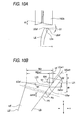
- FIG. 7 is a partial sectional view on the ear side in a state of attaching the demo lens DLE in a rimless frame (rear-fixing frame) of one hole having a turn-stopping contact area extending from the lens rear side to the lens edge surface.
- a rimless frame rear-fixing frame
- an end piece 604 constituting a member of connecting the rear-fixing frame is fixed to a hole opened at the demo lens DLE by using one screw 602.
- a contact area 606 bent from the endpiece 604 forward for a wearer is fixed to be brought into contact with an end surface (edge surface) of the demo lens DLE.
- a temple 610 is extended from the contact portion 606.
- a bridge (not shown) of the nose side portion is similarly provided with a connecting member in correspondence with the endpiece 604 and a contact area, which are fixed to the hole formed at the demo lens DLE by the screw.
- the demo lens DLE is drilled to form the hole in a direction of the normal line L1 perpendicular to the front surface of the demo lens DLE at a position P1 at a distance W from the target lens shape center FC. Further, it is assumed that the demo lens DLE is fixed by the screw 602. It is assumed that the demo lens DLE having the surface curve, for example, of a curve value C of 4 curve is attached. Normally, when the hole is opened perpendicularly to the surface of the lens front surface (normal line direction), a state of bringing the screw 602 into contact with the lens front surface is easy to be stabilized.
- the curve value expressing the lens curve customarily is indicated by a numerical value constituted by dividing 523 by a radius (mm) of the curve.
- Fig. 8 is a view for explaining the method of setting the hole angle in the direction perpendicular to the lens front surface in designating the hole position with reference to the lens rear surface.
- the x-axis and ⁇ -axis on Fig. 8 are axes for convenience for explanation, which are different from the X-axis and Y-axis in the apparatus construction in Fig. 1 and the x-axis and ⁇ -axis in Fig. 5A .
- the center of the curvature of a lens front surface curve LEf is located at a center point O and the center FC of the target lens shape is located on the x-axis. It is assumed that the x-axis coincides with the chuck axes 102L and 102R.
- the point A on the lens rear surface side indicates the hole position designated with reference to the lens rear surface.
- the point B indicates the position on the lens front surface LEf side in the direction passing the point A and also in parallel to the x-axis.
- the radius r of the front surface curve (numerical value obtained by dividing 523 by the curve value) is acquired by the control portion 50. Since the front surface position on the x-axis constituting the chuck axes is known, the position of the target lens shape center FCf on the lens front surface side is also known. Since the distance from the target lens shape center FCf on the lens front surface side is the radius r, the position of the point O on the x-axis is thereby acquired.
- the points A and B in the x-axis direction are detected by contact of the measuring piece 306R of the measuring portion 300R and the measuring piece 306F of the measuring portion 300F, respectively.
- the measuring portions 300R and 300F are driven by the control portion 50 on the basis of the hole position data inputted.
- Fig. 8 assuming that the distance from the point A to the point B is W1, the distance between the point B and the target lens shape center FCf on the front surface side in the x-axis direction is Mf, and the distance between the point O and the point A (or point B) in the ⁇ -axis direction (which is acquired from the hole position data) is H, the coordinates of the point A is (r-W1-Mf, H) in the order of the positions on the x-axis and the y-axis.
- the coordinates of the point B is (r-Mf, H).
- Equation 3 H r - Mf - W ⁇ 1 ⁇ x
- the position of the point D constitutes the standard of the hole depth d652 which is set on the input column 534. Since the hole position on the lens front surface in the x-axis direction is acquired precisely, the hole depth designated by spot facing (hole depth in the direction perpendicular to the lens front surface) can be assured precisely.
- the moving speed of an end mill 435 for the lens LE during the drilling is set to be slower than its moving speed until the tip of the end mill 435 reaches the lens front surface. This intends to operate the end mill 435 so that it repeats the advance and retreat for the lens LE during the drilling to exhaust cutting lees. On the contrary, if the moving speed of the end mill 435 toward the hole is set to be equal to that during the drilling, disadvantageously, the time taken from the start of processing to the end thereof is greatly lengthened.
- the hole angle perpendicular to the lens front surface may be acquired in the following manner without inputting the curve value of the front surface.
- a plurality of positions Bn B2, B3, B4, ...) in the outside vicinity of the position of the point B1 nearly opposite to the point A of the hole position inputted with reference to the lens rear surface are measured by the measuring portion 300F.
- the angles of inclination Sfn Sf1, Sf2, ...) of the lens front surface LEf are acquired. The measurement is carried out at small intervals of e.g. 0.5 mm.
- the corresponding perpendicular lines Tfn (Tf1, Tf2, ...) are acquired, respectively.
- the straight line T650 passing the point A of the hole position on the lens rear surface is acquired.
- the hole angle ⁇ 3 in the direction nearly perpendicular to the lens front surface is set.
- the hole position on the lens front surface can be acquired by computing the intersection point D between the straight line T650 and the linear segment connecting the two points on the lens front surface where the straight line T650 passes.
- the hole angle ⁇ 3 perpendicular to the lens front surface can be set more precisely.
- the hole position D passing the lens front surface can be acquired more precisely.
- the measuring portions 300F and 300R are driven by the control portion 50.
- the point A on the lens rear surface and the point B on the lens front surface are measured, thereby setting the angle ⁇ 3 in the direction passing the hole position A on the lens rear surface and being perpendicular to the lens front surface.
- the peripheral edge of the lens LE is roughed and thereafter finished to be flat.
- the rotating axis of the end mill 435 is inclined at the hole angle ⁇ 3 set as described above so as to pass the hole position (point A in Figs. 8 and 9 ) inputted with reference to the lens rear surface.
- the lens LE is moved toward the end mill 435 in the direction of the angle ⁇ 3.
- the drilling is carried out in the direction of the angle ⁇ 3 passing the hole position on the lens rear surface (point A in Figs. 8 and 9 ).
- the drilling may be carried out prior to the processing of the lens peripheral edge.
- the lens LE is moved at a relatively high speed until the tip of the end mill 435 reaches the point D which is the position on the lens front surface. After the tip of the end mill 435 has reached the position on the lens front surface, the moving speed of the lens LE is reduced so that the end mill 435 moves while repeating the advance and retreat for the lens LE in order to exhaust cutting lees.
- the processing time is shortened while assuring the precision of the drilling.
- the edge LEe of the lens LE after the flat finishing is finished to have the inclination of the angle ⁇ 1.
- the angle ⁇ 1 is set so that the edge position LEer on the lens rear surface is located more inside than the edge position LEef of the lens front surface.
- the angle ⁇ 1 is for example 2.5°.
- Fig. 10B is a sectional view of the lens LE after the flat-finishing.
- the distance from the lens edge position on the lens rear surface of the demo lens to the hole position P3 on the lens rear surface is xh.
- the distance from the target lens shape center is inputted, by subtracting the inputted distance from the target lens shape data, the distance xh is acquired. It is assumed that the lens edge of the demo lens does not have the angle ⁇ 1 but in parallel to the x-axis.
- the target lens shape data represents the lens front surface shape
- a gap ⁇ xcor will be generated between the endpiece 604 of the rear-fixing frame and the edge position LEer on the lens rear surface after the finishing.
- the contact state of the lens endpiece 604 with the lens rear surface LEr and lens edge LEer becomes unstable so that the turn of the frame cannot be stopped.
- the drilling is carried out at the hole position P5 obtained by correcting the hole position P3 on the lens rear surface inwardly by the gap ⁇ xcor.
- the edge position LEef on the lens front surface and the first edge position LEer1 on the lens rear surface are acquired. Further, as regards the lens rear surface, its outside or inside from the target lens shape by the distance ⁇ (0.5 mm) is measured thereby to acquire the second edge position LEer2. It is assumed that the angle ⁇ 2 formed by the linear segment connecting these two points with the x-axis approximately constitutes the angle of inclination of the lens rear surface LEr. The angle of inclination ⁇ 2 can be acquired from the first edge position LEer1 and second edge position LEer2.
- ⁇ ⁇ xcor tan ⁇ ⁇ 1 ⁇ tan ⁇ ⁇ 2 tan ⁇ ⁇ 1 + tan ⁇ ⁇ 2 ⁇ W ⁇ 2 Since the distance W2 can be acquired by measuring the edge positions on the lens front surface and lens rear surface, from Equation 6, ⁇ xcor can be acquired. Namely, the edge position LEer on the lens rear surface expected after the finishing is acquired. Thus, the position P5 shifted from the inputted hole position P3 by ⁇ xcor can be acquired.
- the rotating axis of the end mill 435 is inclined according to the angle ⁇ 4 and the lens LE is moved in the direction of the angle ⁇ 4 by driving the carriage 101 in the XY directions so that the tip of the end mill 435 passes the point A of the hole position on the lens rear surface.
- the drilling is carried out in the direction perpendicular to the lens rear surface by inputting the hole position with reference to the lens rear surface.
- the hole position is inputted with reference to the lens rear surface.
- whether the direction of the hole angle should be set perpendicular to the lens front surface or perpendicular to the lens rear surface may be selected according to whether the lens LE is a minus lens or a plus lens.
- the lens thickness degree is constant and the endpiece of the rear-fixing frame is attached along the lens rear surface.
- the curve of the lens rear surface is changed according the lens degree and the curve of the lens front surface changes less than that of the lens front surface of the demo lens.
- the opening angle of the temple of the rear-fixing frame with the demo lens attached may be adjusted by a small degree.
- the curve of the lens front surface is changed according the lens thickness degree and the curve of the lens rear surface changes less than that of the lens rear surface of the demo lens.
- the opening angle of the temple of the rear-fixing frame with the demo lens attached may be adjusted by a small degree.
- Fig. 12 schematically, the curvature center of the lens rear surface LEr is located at point O and the target lens shape center FC is located on the y-axis.
- the x-axis and y-axis in Fig. 12 are axes for convenience for explanation and different from the x-axis and y-axis in Fig. 8 . It is assumed that y-axis coincide with the chuck axes 102L and 102R.
- the position of point J1 in the ⁇ -axis direction on the lens rear surface LEr is detected by measuring portion 300R.
- Equation 7 denotes the distance of the point J1 in the x-axis direction which is given by inputting the hole position I1.
- the radius rp3 may be inputted by the measurement of the lens rear surface by a curve meter. As regards the locus on the lens rear surface LEr, the relationship expressed by the following Equation 8 holds.
- the edge position expected after the finishing of the lens rear surface LEr is point L1.
- the end surface of the lens LE has been finished in parallel to the lens chuck axis (y-axis).
- the value of the point L1 in the y-axis direction is acquired from the measurement by the measuring portion 300R on the basis of the target lens shape data.
- Equation 9 Assuming that the radius of the lens rear surface curve of the demo lens is rd3, the distance from the y-axis to the point L1 is W3, the center of the radius rd3 of the demo lens rear surface DLEr passing the point L1 is point A3 and its value on the y-axis is a3, as regards the locus of the demo lens rear surface DLEr, the following Equation 9 holds.
- rd3 is inputted by measuring the lens rear surface of the demo lens.
- the value of a3 is acquired by substituting the value of point L1 on the x-axis, i.e. W3 for Equation 8 and substituting the y-coordinate of the point L1 thus acquired for Equation 9.
- the equation thus acquired is expressed as follows.
- the straight line 702 that is the locus of drilling passes the point 11 which is the center of the screw hole H604 of the end piece 604, and its hole angle is oriented in the direction of angle ⁇ 4 from the lens chuck axis.
- the angle ⁇ 4 is the value previously inputted as an optional angle or the value as the angle of the normal line direction to the lens front surface.
- the straight line 702 can be expressed as the following relational equation, Equation 11.
- Equation 12 tan ( ⁇ 2 - ⁇ ⁇ 4 ) x + ⁇ ⁇ 3 + rd ⁇ 3 2 - H ⁇ 3 2 - H ⁇ 3 ⁇ tan ⁇ 2 - ⁇ ⁇ 4
- This point M is set as the hole position of the lens rear surface and the quantity of deviation ⁇ H between the point J1 and the point M is acquired as a difference therebetween.
- the drilling is carried out in the direction passing the point M at the angle ⁇ 4.
- the control portion 50 performs correction operation for the inputted hole position data for the position of the point M.
- the deviation between the screw hole H604 of the endpiece 604 and the hole position on the lens rear surface is corrected so that in assembling the rear-fixing frame, the opening angle of the temple 610 can be adjusted by a small degree, thereby facilitating the adjustment.
- the edge end surface of the lens LE after the flat finishing is processed at an inclination of the angle ⁇ 1, as described above, it is preferred to correct the hole position on the basis of the gap ⁇ xcor.
- the radius rp3 of the lens rear surface LEr curve as in Fig. 9 , the inclination of the lens rear surface can be acquired on the basis of the measurement results of the plurality of positions on the lens rear surface by the measuring portion 300R.
- the measuring and detecting methods is not limited to the above embodiment. Of course, various methods which are known in the art and various simple methods may be employed.
Landscapes
- Engineering & Computer Science (AREA)
- Mechanical Engineering (AREA)
- Physics & Mathematics (AREA)
- Ophthalmology & Optometry (AREA)
- Health & Medical Sciences (AREA)
- General Physics & Mathematics (AREA)
- Optics & Photonics (AREA)
- Mining & Mineral Resources (AREA)
- Chemical & Material Sciences (AREA)
- Ceramic Engineering (AREA)
- Inorganic Chemistry (AREA)
- General Health & Medical Sciences (AREA)
- Drilling And Boring (AREA)
- Grinding And Polishing Of Tertiary Curved Surfaces And Surfaces With Complex Shapes (AREA)
- Perforating, Stamping-Out Or Severing By Means Other Than Cutting (AREA)
- Eyeglasses (AREA)
Applications Claiming Priority (1)
| Application Number | Priority Date | Filing Date | Title |
|---|---|---|---|
| JP2007024897A JP4975469B2 (ja) | 2007-02-02 | 2007-02-02 | 眼鏡レンズ加工装置 |
Publications (2)
| Publication Number | Publication Date |
|---|---|
| EP1952943A2 true EP1952943A2 (fr) | 2008-08-06 |
| EP1952943A3 EP1952943A3 (fr) | 2008-12-31 |
Family
ID=39362270
Family Applications (1)
| Application Number | Title | Priority Date | Filing Date |
|---|---|---|---|
| EP08001727A Withdrawn EP1952943A3 (fr) | 2007-02-02 | 2008-01-30 | Appareil de traitement de l'objectif à loupe |
Country Status (5)
| Country | Link |
|---|---|
| US (1) | US20080186446A1 (fr) |
| EP (1) | EP1952943A3 (fr) |
| JP (1) | JP4975469B2 (fr) |
| KR (1) | KR101415475B1 (fr) |
| CN (1) | CN101234514B (fr) |
Cited By (1)
| Publication number | Priority date | Publication date | Assignee | Title |
|---|---|---|---|---|
| CN106002535A (zh) * | 2015-03-31 | 2016-10-12 | 尼德克株式会社 | 眼镜镜片加工装置 |
Families Citing this family (7)
| Publication number | Priority date | Publication date | Assignee | Title |
|---|---|---|---|---|
| EP2199021A1 (fr) | 2008-12-22 | 2010-06-23 | Essilor International (Compagnie Générale D'Optique) | Procédé et appareil pour la fabrication d'une lentille optique |
| JP5372628B2 (ja) * | 2009-07-08 | 2013-12-18 | 株式会社ニデック | 眼鏡レンズ加工装置及び該装置に使用されるヤゲン加工具 |
| JP6015021B2 (ja) * | 2011-02-16 | 2016-10-26 | 株式会社ニデック | 眼鏡レンズ加工形状取得方法及び眼鏡レンズ加工形状取得装置 |
| KR101828420B1 (ko) * | 2013-09-18 | 2018-02-12 | 유엣-찬 렁 | 모듈화 안경 및 그것의 제조방법 |
| KR102344250B1 (ko) * | 2016-07-01 | 2021-12-27 | 가부시키가이샤 니데크 | 안경 렌즈 가공 장치 및 가공 제어 데이터 작성 프로그램 |
| CN107234515A (zh) * | 2017-06-06 | 2017-10-10 | 宁波法里奥光学科技发展有限公司 | 一种镜片磨边机及镜片切边方法 |
| CN110883709A (zh) * | 2018-09-10 | 2020-03-17 | 合肥江丰电子材料有限公司 | 靶材抛光装置 |
Citations (5)
| Publication number | Priority date | Publication date | Assignee | Title |
|---|---|---|---|---|
| JPH0493164A (ja) | 1990-08-09 | 1992-03-25 | Nidek Co Ltd | 眼鏡レンズ研削加工機 |
| US5333412A (en) | 1990-08-09 | 1994-08-02 | Nidek Co., Ltd. | Apparatus for and method of obtaining processing information for fitting lenses in eyeglasses frame and eyeglasses grinding machine |
| JP2003145328A (ja) | 2001-11-08 | 2003-05-20 | Nidek Co Ltd | 眼鏡レンズ加工装置 |
| JP2006189659A (ja) | 2005-01-06 | 2006-07-20 | Nidek Co Ltd | 眼鏡レンズ加工装置 |
| JP2006239782A (ja) | 2005-02-28 | 2006-09-14 | Nidek Co Ltd | 眼鏡レンズ加工装置 |
Family Cites Families (22)
| Publication number | Priority date | Publication date | Assignee | Title |
|---|---|---|---|---|
| DE3590087T1 (de) * | 1984-03-02 | 1986-06-05 | Hoya Corp., Tokio/Tokyo | Brillengestellform-Datenvorrichtung |
| US4607459A (en) | 1984-08-10 | 1986-08-26 | Wen Products, Inc. | Combined hollow grinder, sharpener and honer |
| US4979311A (en) * | 1990-03-14 | 1990-12-25 | Bizer Jerry L | Instrument for determining the setting of a lens edger device to produce a properly sized lens |
| JP3029054B2 (ja) * | 1991-02-28 | 2000-04-04 | 株式会社ニデック | レンズメータ |
| JP3602175B2 (ja) * | 1994-12-09 | 2004-12-15 | 株式会社トプコン | リムレスレンズ用穴開け装置とこれを用いた玉摺機とこの玉摺機に使用されるメガネ用形状測定装置 |
| JP4034848B2 (ja) * | 1997-04-30 | 2008-01-16 | 株式会社ニデック | 眼鏡レンズ研削加工装置 |
| DE19804428A1 (de) * | 1998-02-05 | 1999-08-19 | Wernicke & Co Gmbh | Verfahren zum Markieren oder Bohren von Löchern in Brillengläsern und Vorrichtung zur Durchführung des Verfahrens |
| JP3730406B2 (ja) * | 1998-04-30 | 2006-01-05 | 株式会社ニデック | 眼鏡レンズ加工装置 |
| JP2000015549A (ja) * | 1998-06-30 | 2000-01-18 | Nidek Co Ltd | 眼鏡レンズ加工装置 |
| DE19834748A1 (de) * | 1998-08-01 | 2000-02-10 | Wernicke & Co Gmbh | Brillenglasrandschleifmaschine |
| DE19914174A1 (de) * | 1999-03-29 | 2000-10-12 | Wernicke & Co Gmbh | Verfahren und Vorrichtung zum Formbearbeiten des Umfangsrandes von Brillengläsern |
| JP3828686B2 (ja) * | 1999-08-31 | 2006-10-04 | 株式会社ニデック | カップ取付装置 |
| GB0011769D0 (en) * | 2000-05-17 | 2000-07-05 | Ball Burnishing Mach Tools | A surface conditioning tool employing compressed non-woven fibres |
| JP4288012B2 (ja) * | 2001-01-05 | 2009-07-01 | 株式会社ニデック | 眼鏡レンズ加工装置 |
| JP2003145400A (ja) * | 2001-11-08 | 2003-05-20 | Nidek Co Ltd | 眼鏡レンズ加工装置 |
| JP4098046B2 (ja) * | 2002-09-20 | 2008-06-11 | 株式会社トプコン | レンズ研削加工装置 |
| EP1445065A1 (fr) * | 2003-02-05 | 2004-08-11 | Nidek Co., Ltd. | Appareil pour le traitement de lentilles ophtalmiques |
| FR2863189B1 (fr) * | 2003-12-03 | 2006-03-10 | Jean-Louis Negroni | Procede de percage de verres optiques a l'aide d'une perceuse a commande numerique, et dispositif de mise en oeuvre dudit procede |
| JP4774203B2 (ja) * | 2004-10-01 | 2011-09-14 | 株式会社ニデック | 眼鏡レンズ加工装置 |
| JP4873878B2 (ja) * | 2005-03-31 | 2012-02-08 | 株式会社ニデック | 眼鏡レンズ周縁加工装置 |
| JP2007007788A (ja) * | 2005-06-30 | 2007-01-18 | Nidek Co Ltd | 眼鏡レンズ加工装置 |
| JP4749892B2 (ja) * | 2006-02-28 | 2011-08-17 | 株式会社ニデック | 穴データ入力装置及びこれを備える眼鏡レンズ加工装置 |
-
2007
- 2007-02-02 JP JP2007024897A patent/JP4975469B2/ja active Active
-
2008
- 2008-01-30 EP EP08001727A patent/EP1952943A3/fr not_active Withdrawn
- 2008-02-01 KR KR1020080010788A patent/KR101415475B1/ko not_active Expired - Fee Related
- 2008-02-01 US US12/024,497 patent/US20080186446A1/en not_active Abandoned
- 2008-02-02 CN CN2008100094535A patent/CN101234514B/zh not_active Expired - Fee Related
Patent Citations (7)
| Publication number | Priority date | Publication date | Assignee | Title |
|---|---|---|---|---|
| JPH0493164A (ja) | 1990-08-09 | 1992-03-25 | Nidek Co Ltd | 眼鏡レンズ研削加工機 |
| US5333412A (en) | 1990-08-09 | 1994-08-02 | Nidek Co., Ltd. | Apparatus for and method of obtaining processing information for fitting lenses in eyeglasses frame and eyeglasses grinding machine |
| JP2003145328A (ja) | 2001-11-08 | 2003-05-20 | Nidek Co Ltd | 眼鏡レンズ加工装置 |
| US6790124B2 (en) | 2001-11-08 | 2004-09-14 | Nidek Co., Ltd. | Eyeglass lens processing apparatus |
| JP2006189659A (ja) | 2005-01-06 | 2006-07-20 | Nidek Co Ltd | 眼鏡レンズ加工装置 |
| US20060178086A1 (en) | 2005-01-06 | 2006-08-10 | Nidek Co., Ltd. | Eyeglass lens processing apparatus |
| JP2006239782A (ja) | 2005-02-28 | 2006-09-14 | Nidek Co Ltd | 眼鏡レンズ加工装置 |
Cited By (2)
| Publication number | Priority date | Publication date | Assignee | Title |
|---|---|---|---|---|
| CN106002535A (zh) * | 2015-03-31 | 2016-10-12 | 尼德克株式会社 | 眼镜镜片加工装置 |
| EP3075508A3 (fr) * | 2015-03-31 | 2016-12-07 | Nidek co., Ltd. | Appareil et procédé de traitement de lentille de lunettes et appareil d'acquisition de données de commande de traitement de verres de lunettes |
Also Published As
| Publication number | Publication date |
|---|---|
| JP4975469B2 (ja) | 2012-07-11 |
| US20080186446A1 (en) | 2008-08-07 |
| EP1952943A3 (fr) | 2008-12-31 |
| JP2008188702A (ja) | 2008-08-21 |
| KR20080072583A (ko) | 2008-08-06 |
| CN101234514B (zh) | 2013-07-03 |
| CN101234514A (zh) | 2008-08-06 |
| KR101415475B1 (ko) | 2014-07-04 |
Similar Documents
| Publication | Publication Date | Title |
|---|---|---|
| KR101403181B1 (ko) | 구멍 데이터 입력 장치 및 이를 갖는 안경 렌즈 가공 장치 | |
| JP5134346B2 (ja) | 眼鏡レンズ周縁加工装置 | |
| US6942542B2 (en) | Eyeglass lens processing apparatus | |
| EP1952943A2 (fr) | Appareil de traitement de l'objectif à loupe | |
| EP1884333B1 (fr) | Procédé de traitement de verres à lunettes | |
| JP2003145328A (ja) | 眼鏡レンズ加工装置 | |
| US8366512B2 (en) | Eyeglass lens processing apparatus for processing periphery of eyeglass lens and eyeglass lens processing method | |
| EP1815941A1 (fr) | Dispositif d'usinage de verres de lunettes | |
| JP4708035B2 (ja) | 眼鏡レンズ加工装置 | |
| US7617579B2 (en) | Eyeglass lens processing apparatus | |
| JP2005074560A (ja) | 眼鏡レンズ加工装置 | |
| US8671532B2 (en) | Eyeglass lens processing apparatus | |
| KR101437160B1 (ko) | 안경 렌즈 가공 장치 | |
| US8260450B2 (en) | Eyeglass lens processing apparatus | |
| KR101415449B1 (ko) | 파셋 가공 영역 설정 장치 및 이것을 갖는 안경 렌즈 가공장치 | |
| JP2007319984A (ja) | 眼鏡レンズ周縁加工装置 | |
| JP2011016191A (ja) | 眼鏡レンズ加工装置及び該装置に使用されるヤゲン加工具 | |
| JP4781973B2 (ja) | 眼鏡レンズ加工装置 |
Legal Events
| Date | Code | Title | Description |
|---|---|---|---|
| PUAI | Public reference made under article 153(3) epc to a published international application that has entered the european phase |
Free format text: ORIGINAL CODE: 0009012 |
|
| AK | Designated contracting states |
Kind code of ref document: A2 Designated state(s): AT BE BG CH CY CZ DE DK EE ES FI FR GB GR HR HU IE IS IT LI LT LU LV MC MT NL NO PL PT RO SE SI SK TR |
|
| AX | Request for extension of the european patent |
Extension state: AL BA MK RS |
|
| PUAL | Search report despatched |
Free format text: ORIGINAL CODE: 0009013 |
|
| AK | Designated contracting states |
Kind code of ref document: A3 Designated state(s): AT BE BG CH CY CZ DE DK EE ES FI FR GB GR HR HU IE IS IT LI LT LU LV MC MT NL NO PL PT RO SE SI SK TR |
|
| AX | Request for extension of the european patent |
Extension state: AL BA MK RS |
|
| 17P | Request for examination filed |
Effective date: 20090626 |
|
| AKX | Designation fees paid |
Designated state(s): DE ES FR GB |
|
| GRAP | Despatch of communication of intention to grant a patent |
Free format text: ORIGINAL CODE: EPIDOSNIGR1 |
|
| STAA | Information on the status of an ep patent application or granted ep patent |
Free format text: STATUS: THE APPLICATION IS DEEMED TO BE WITHDRAWN |
|
| 18D | Application deemed to be withdrawn |
Effective date: 20100727 |