EP1953341A2 - Aube d'une turbomachine et procédé d'agencement - Google Patents
Aube d'une turbomachine et procédé d'agencement Download PDFInfo
- Publication number
- EP1953341A2 EP1953341A2 EP08250021A EP08250021A EP1953341A2 EP 1953341 A2 EP1953341 A2 EP 1953341A2 EP 08250021 A EP08250021 A EP 08250021A EP 08250021 A EP08250021 A EP 08250021A EP 1953341 A2 EP1953341 A2 EP 1953341A2
- Authority
- EP
- European Patent Office
- Prior art keywords
- blade
- turbomachine
- leading edge
- operating condition
- radial
- Prior art date
- Legal status (The legal status is an assumption and is not a legal conclusion. Google has not performed a legal analysis and makes no representation as to the accuracy of the status listed.)
- Withdrawn
Links
- 238000000034 method Methods 0.000 title claims description 59
- 238000013461 design Methods 0.000 title description 16
- 239000012530 fluid Substances 0.000 claims abstract description 52
- 230000035939 shock Effects 0.000 claims description 88
- 238000011144 upstream manufacturing Methods 0.000 claims description 55
- 230000002238 attenuated effect Effects 0.000 claims description 30
- 238000004590 computer program Methods 0.000 claims description 4
- 230000000644 propagated effect Effects 0.000 claims description 4
- 238000004364 calculation method Methods 0.000 description 11
- 238000012938 design process Methods 0.000 description 11
- 230000003068 static effect Effects 0.000 description 9
- 238000004458 analytical method Methods 0.000 description 8
- 230000009467 reduction Effects 0.000 description 8
- 230000008569 process Effects 0.000 description 7
- 230000004048 modification Effects 0.000 description 6
- 238000012986 modification Methods 0.000 description 6
- 230000000694 effects Effects 0.000 description 5
- 239000013598 vector Substances 0.000 description 5
- 238000009826 distribution Methods 0.000 description 4
- 239000007787 solid Substances 0.000 description 4
- 238000013459 approach Methods 0.000 description 3
- 230000005855 radiation Effects 0.000 description 3
- 230000007704 transition Effects 0.000 description 3
- 241000243251 Hydra Species 0.000 description 2
- 230000008859 change Effects 0.000 description 2
- 239000000470 constituent Substances 0.000 description 2
- 238000000354 decomposition reaction Methods 0.000 description 2
- 230000007423 decrease Effects 0.000 description 2
- 238000013400 design of experiment Methods 0.000 description 2
- 238000002474 experimental method Methods 0.000 description 2
- 238000000605 extraction Methods 0.000 description 2
- QRXWMOHMRWLFEY-UHFFFAOYSA-N isoniazide Chemical compound NNC(=O)C1=CC=NC=C1 QRXWMOHMRWLFEY-UHFFFAOYSA-N 0.000 description 2
- 239000000203 mixture Substances 0.000 description 2
- 230000001902 propagating effect Effects 0.000 description 2
- 238000009825 accumulation Methods 0.000 description 1
- 230000001154 acute effect Effects 0.000 description 1
- 230000007613 environmental effect Effects 0.000 description 1
- 238000004519 manufacturing process Methods 0.000 description 1
- 238000005259 measurement Methods 0.000 description 1
- 230000000737 periodic effect Effects 0.000 description 1
- 238000011946 reduction process Methods 0.000 description 1
- 230000001105 regulatory effect Effects 0.000 description 1
- 238000009987 spinning Methods 0.000 description 1
- 238000006467 substitution reaction Methods 0.000 description 1
- 238000012360 testing method Methods 0.000 description 1
- 238000011179 visual inspection Methods 0.000 description 1
Images




Classifications
-
- F—MECHANICAL ENGINEERING; LIGHTING; HEATING; WEAPONS; BLASTING
- F01—MACHINES OR ENGINES IN GENERAL; ENGINE PLANTS IN GENERAL; STEAM ENGINES
- F01D—NON-POSITIVE DISPLACEMENT MACHINES OR ENGINES, e.g. STEAM TURBINES
- F01D5/00—Blades; Blade-carrying members; Heating, heat-insulating, cooling or antivibration means on the blades or the members
- F01D5/12—Blades
- F01D5/14—Form or construction
- F01D5/141—Shape, i.e. outer, aerodynamic form
-
- F—MECHANICAL ENGINEERING; LIGHTING; HEATING; WEAPONS; BLASTING
- F02—COMBUSTION ENGINES; HOT-GAS OR COMBUSTION-PRODUCT ENGINE PLANTS
- F02K—JET-PROPULSION PLANTS
- F02K3/00—Plants including a gas turbine driving a compressor or a ducted fan
- F02K3/02—Plants including a gas turbine driving a compressor or a ducted fan in which part of the working fluid by-passes the turbine and combustion chamber
- F02K3/04—Plants including a gas turbine driving a compressor or a ducted fan in which part of the working fluid by-passes the turbine and combustion chamber the plant including ducted fans, i.e. fans with high volume, low pressure outputs, for augmenting the jet thrust, e.g. of double-flow type
- F02K3/06—Plants including a gas turbine driving a compressor or a ducted fan in which part of the working fluid by-passes the turbine and combustion chamber the plant including ducted fans, i.e. fans with high volume, low pressure outputs, for augmenting the jet thrust, e.g. of double-flow type with front fan
-
- F—MECHANICAL ENGINEERING; LIGHTING; HEATING; WEAPONS; BLASTING
- F04—POSITIVE - DISPLACEMENT MACHINES FOR LIQUIDS; PUMPS FOR LIQUIDS OR ELASTIC FLUIDS
- F04D—NON-POSITIVE-DISPLACEMENT PUMPS
- F04D21/00—Pump involving supersonic speed of pumped fluids
-
- F—MECHANICAL ENGINEERING; LIGHTING; HEATING; WEAPONS; BLASTING
- F04—POSITIVE - DISPLACEMENT MACHINES FOR LIQUIDS; PUMPS FOR LIQUIDS OR ELASTIC FLUIDS
- F04D—NON-POSITIVE-DISPLACEMENT PUMPS
- F04D29/00—Details, component parts, or accessories
- F04D29/26—Rotors specially for elastic fluids
- F04D29/32—Rotors specially for elastic fluids for axial flow pumps
- F04D29/321—Rotors specially for elastic fluids for axial flow pumps for axial flow compressors
- F04D29/324—Blades
-
- F—MECHANICAL ENGINEERING; LIGHTING; HEATING; WEAPONS; BLASTING
- F05—INDEXING SCHEMES RELATING TO ENGINES OR PUMPS IN VARIOUS SUBCLASSES OF CLASSES F01-F04
- F05D—INDEXING SCHEME FOR ASPECTS RELATING TO NON-POSITIVE-DISPLACEMENT MACHINES OR ENGINES, GAS-TURBINES OR JET-PROPULSION PLANTS
- F05D2240/00—Components
- F05D2240/10—Stators
- F05D2240/12—Fluid guiding means, e.g. vanes
- F05D2240/121—Fluid guiding means, e.g. vanes related to the leading edge of a stator vane
-
- F—MECHANICAL ENGINEERING; LIGHTING; HEATING; WEAPONS; BLASTING
- F05—INDEXING SCHEMES RELATING TO ENGINES OR PUMPS IN VARIOUS SUBCLASSES OF CLASSES F01-F04
- F05D—INDEXING SCHEME FOR ASPECTS RELATING TO NON-POSITIVE-DISPLACEMENT MACHINES OR ENGINES, GAS-TURBINES OR JET-PROPULSION PLANTS
- F05D2240/00—Components
- F05D2240/20—Rotors
- F05D2240/30—Characteristics of rotor blades, i.e. of any element transforming dynamic fluid energy to or from rotational energy and being attached to a rotor
- F05D2240/303—Characteristics of rotor blades, i.e. of any element transforming dynamic fluid energy to or from rotational energy and being attached to a rotor related to the leading edge of a rotor blade
-
- F—MECHANICAL ENGINEERING; LIGHTING; HEATING; WEAPONS; BLASTING
- F05—INDEXING SCHEMES RELATING TO ENGINES OR PUMPS IN VARIOUS SUBCLASSES OF CLASSES F01-F04
- F05D—INDEXING SCHEME FOR ASPECTS RELATING TO NON-POSITIVE-DISPLACEMENT MACHINES OR ENGINES, GAS-TURBINES OR JET-PROPULSION PLANTS
- F05D2250/00—Geometry
- F05D2250/10—Two-dimensional
- F05D2250/18—Two-dimensional patterned
- F05D2250/184—Two-dimensional patterned sinusoidal
-
- F—MECHANICAL ENGINEERING; LIGHTING; HEATING; WEAPONS; BLASTING
- F05—INDEXING SCHEMES RELATING TO ENGINES OR PUMPS IN VARIOUS SUBCLASSES OF CLASSES F01-F04
- F05D—INDEXING SCHEME FOR ASPECTS RELATING TO NON-POSITIVE-DISPLACEMENT MACHINES OR ENGINES, GAS-TURBINES OR JET-PROPULSION PLANTS
- F05D2260/00—Function
- F05D2260/96—Preventing, counteracting or reducing vibration or noise
-
- Y—GENERAL TAGGING OF NEW TECHNOLOGICAL DEVELOPMENTS; GENERAL TAGGING OF CROSS-SECTIONAL TECHNOLOGIES SPANNING OVER SEVERAL SECTIONS OF THE IPC; TECHNICAL SUBJECTS COVERED BY FORMER USPC CROSS-REFERENCE ART COLLECTIONS [XRACs] AND DIGESTS
- Y02—TECHNOLOGIES OR APPLICATIONS FOR MITIGATION OR ADAPTATION AGAINST CLIMATE CHANGE
- Y02T—CLIMATE CHANGE MITIGATION TECHNOLOGIES RELATED TO TRANSPORTATION
- Y02T50/00—Aeronautics or air transport
- Y02T50/60—Efficient propulsion technologies, e.g. for aircraft
Definitions
- the present invention relates to blades for a turbomachine, turbomachines including a casing and a cascade of circumferentially spaced blades, and methods of designing and producing blades.
- the blades may be fan blades and the turbomachines may be aero gas turbine engines.
- the noise produced by an aero gas turbine engine is the accumulation of many individual noise sources.
- Sources related to the turbomachinery contain both broadband and tonal components, while the jet noise source is broadband in nature.
- the fan is typically a major source of tone noise emanating from the inlet, particularly when the engine is at an operating condition which generates supersonic fluid flow at the fan blades.
- tone noise is produced by shock waves emanating from the fan blades and propagating upstream through the engine intake.
- Such tone noise typically has components at the fan blade passing frequency (BPF) and at frequency multiples thereof.
- the noise can also include "buzz" caused by variations in the shock waves produced by adjacent fan blades. The variations themselves can be caused, for example, by small differences in manufactured fan blade shapes. Buzz occurs at harmonics of shaft rotation frequency. Although buzz can be the predominant part of the tone noise produced by a fan, it is effectively a distortion of the BPF tone and its harmonics. Therefore, if the BPF tone and its harmonics are attenuated close to the source, buzz should also be attenuated.
- an “operating condition” we mean a combination of the turbomachine rotational speed and working fluid mass flow rate at a specified inlet stagnation pressure and stagnation temperature that provides a given pressure ratio across a set of blades, which are typically the blades of a fan.
- sweep angle we mean the acute angle at any arbitrary radial position on the leading edge of a blade between a line tangent to the leading edge at that position and a plane perpendicular to the working fluid relative velocity vector at that position.
- sweep angle we mean the acute angle at any arbitrary radial position on the leading edge of a blade between a line tangent to the leading edge at that position and a plane perpendicular to the working fluid relative velocity vector at that position.
- forward sweep angle we mean a sweep angle where the radially outward extension of the line tangent to the leading edge lies on the upstream side of the plane perpendicular to the working fluid relative velocity vector.
- rearward sweep angle we mean a sweep angle where the radially outward extension of the line tangent to the leading edge lies on the downstream side of the plane perpendicular to the working fluid relative velocity vector.
- a turning point we mean a local maximum or minimum in a quantity.
- the gradient of the quantity is zero. From a position at the turning point, the quantity either increases in both directions (for a local minimum) or decreases in both directions (for a local maximum).
- tone noise we mean noise at the blade passing frequency (BPF) and/or at one or more frequency multiples thereof.
- BPF blade passing frequency
- buzz may come to dominate the tone noise.
- the turbomachine is considered to produce tone noise. That is, it is irrelevant if a far field observer is not be able to hear the tone noise as long as that tone noise does in fact exist and could be measured, for example, by a microphone positioned in the turbomachine adjacent the blades.
- the present invention is at least partly based on the inventors' insight that tone noise emanating from a turbomachine can be reduced by directing acoustic power into those acoustic modes which are better attenuated by the machine itself. A further insight of the inventors was that this can be achieved by careful control of the blade leading edge position with spanwise distance.
- the present invention provides a blade for a turbomachine which is shaped to direct acoustic power into well-attenuated acoustic modes, and a corresponding blade design methodology.
- Figure 1a is a schematic cross-sectional view through adjacent fan blades 1 of an aero gas turbine engine, and shows a type of shock structure that can be produced by the blades at a supersonic operating condition.
- Oblique shocks 2 are formed near the leading edges.
- the oblique shock on the suction side of each blade propagates away from the blade row and spirals towards the engine inlet, while the oblique shock on the pressure side of the blade lies inside the inter-blade passage and merges with a normal shock 3 formed on the suction surface of the adjacent blade.
- different shock structures are possible. For instance, at some conditions there will be a single shock positioned upstream of the leading edge of each blade. At other conditions two distinct shocks will be present, one upstream of the leading edge of each blade and another in each blade passage.
- Figure 1b shows schematically the static pressure along the dashed line A-A in Figure 1a .
- the static pressure varies in time at a frequency which matches the BPF, giving rise to tone noise at the BPF and harmonics thereof.
- the inlet air passageway is bounded on the outside by a casing and on the inside by a hub or spinner. This arrangement approximates to an annular passageway bounded by two concentric cylinders.
- an input periodic pressure distribution p(s,t) (where s is circumferential distance around the annulus, and t is time), which fluctuates at a driving frequency f (i.e. the BPF), can be resolved into a linear sum of simple fourier modes p m (s,t).
- a m ⁇ are complex coefficients and p m ⁇ (r) are linear combinations of Y and J-type Bessel functions of circumferential order m and radial order ⁇ such that the gradient at inner and outer annulus walls is zero.
- each circumferential order m represents a particular frequency (m times shaft frequency), and for a given m the noise heard at that frequency by an observer is the sum of the contributions from each of the radial modes ⁇ .
- each Bessel-fourier harmonic (or "mode) can only propagate along the duct if the angular velocity at which the disturbance sweeps around the annulus exceeds a certain value (the "cut-on” point).
- the cut-on point is different for each radial and circumferential mode, and also varies with the amplitude of the mean flow. It can, however, be calculated using a well-known formula, as was recognised (for instance) by Tyler and Sofrin in the paper referenced above.
- the rate at which the disturbance sweeps around the annulus is identically the rotor speed.
- the cut-on point can be less than or greater than unity depending on the mean flow and the circumferential and radial order.
- Figure 3 is a schematic longitudinal cross-section of a typical aero engine intake, and shows a fan blade 5, hub 6, spinner 7, inlet cowl 8, acoustic liner 9, air intake passage 10 and engine axis O-O.
- acoustic propagation in terms of modes. These modes are still fourier harmonics circumferentially, but (at least in the case of radially non-uniform flow) their radial form is no longer a combination of Bessel functions and sometimes has to be determined numerically.
- Figure 4 shows the radial pressure distribution for a particular mode in an annular hardwall duct with uniform axial mean flow, compared with an equivalent mode in a duct with the same mean flow but with the wall impedance set to match the effect of an acoustic liner.
- each mode can still be associated with an axial wavenumber that represents its attenuation rate along the duct.
- cut-on waves propagate without attenuation.
- the attenuation rate varies continuously with the rate at which the signal sweeps around the annulus, but shows a similar trend in that attenuation rates tend to decrease as signal speed increases.
- Real ducts are not necessarily axisymmetric. Mean flow is not necessarily uniform in the circumferential direction. More significantly the shocks forming the noise generally decay non-linearly through the inlet.
- a modal description can still characterise the noise content at a particular axial plane, particularly if upstream and downstream travelling modes are distinguished, as shown in the case of a hardwall duct by A.G. Wilson, 2001, A Method for Deriving Tone Noise Information from CFD Calculations on the Aeroengine Fan Stage, Paper MP-79-P-03-Wilson, presented at the RTO/AVT Meeting, Manchester UK, 8-11 Oct.
- the radial modes for upstream propagation are independent in the sense that each can be associated with a given power level, and the total acoustic power is the sum of its constituents.
- radial modes are not independent in this fashion, the total acoustic power at any axial plane including cross-products between different modal coefficients.
- the total pressure field can still be defined as a linear sum of the individual modes, and tracking the mode coefficients allows the whole field to be recalculated and thence the total acoustic power.
- a general aspect of the present invention involves changing the blade shape (and particularly the leading edge position) to reduce or minimise the acoustic content or power at the BPF or harmonic frequency thereof in the upstream-travelling radial (lined) mode with axial wavenumber showing it to be the least attenuated mode with upstream axial distance.
- the least attenuated lined mode is the one with the least radial variation, and is thus equivalent to the lowest radial order Bessel-fourier mode in the hardwall uniform axial flow case.
- first, second etc. radial modes Strictly speaking, however, these refer to the lined modes in order of attenuation rate, as defined by the axial wavenumber, starting with the least attenuated.
- Figure 5 shows schematically rates of attenuation for different radial modes produced by a lined engine intake at the BPF.
- a first aspect of the invention provides a blade for a turbomachine, the blade extending, in use, in a radial direction relative to the axis of the turbomachine, and the turbomachine having at least one operating condition which generates supersonic fluid flow at the blade, wherein the blade is adapted to provide, at the supersonic operating condition, a leading edge sweep angle which varies such that successive radial positions (i) to (iii) along the leading edge are at respective sweep angle turning points, position (i) being the radially inner and position (iii) the radially outer of the positions, and position (i) being at or radially outward of the 30% span position, where 0% span is the radially innermost point of the leading edge and 100% span is the radially outermost point of the leading edge.
- a blade having a leading edge shaped to provide such sweep angle variation can reduce or minimise the acoustic content or power at the BPF or harmonic frequency thereof in the upstream-travelling radial (lined) mode with axial wavenumber showing it to be the least attenuated mode with upstream axial distance.
- position (i) is at or radially outward of the 40% or 50% span position.
- the turning points at positions (i) and (iii) are at rearward swept portions of leading edge.
- the turning point at position (ii) is at a forward swept portion of leading edge.
- the sweep angle at position (iii) may be at least 20° and is preferably at least 30°, 40° or 50°.
- position (iii) is radially inward of the 100% span position.
- position (iii) is on a portion of the leading edge which extends from 65% to 100% of the leading edge span, more preferably from 80% to 98% of the leading edge span, and yet more preferably from 90% to 98% or from 93% to 98%.
- the blade may have a radially outermost portion of leading edge which is forward swept.
- the blade may have one or more further sweep angle turning points at other positions on the leading edge.
- the leading edge sweep angle may vary so as to provide at successive radially outward positions consecutive forward swept, rearward swept, forward swept, rearward swept, and forward swept portions.
- the radially innermost forward swept portion can commence at 0% span. Such an arrangement may improve the mechanical stability of the blade.
- the radially outermost forward swept portion can end at 100% span.
- the leading edge sweep angle varies smoothly (i.e. is continuous) over the entire span of the blade.
- a second aspect of the invention provides a blade for a turbomachine, the blade extending, in use, in a radial direction relative to the axis of the turbomachine, and the turbomachine having at least one operating condition which generates supersonic fluid flow at the blade, wherein the blade is shaped such that, at the supersonic operating condition, it produces first and second pressure shocks in the working fluid, the shocks extending out to a plane which is normal to the axis of the turbomachine and which is upstream of the radially outermost point of the blade leading edge relative to the overall direction of fluid flow through the turbomachine, and the shocks being radially spaced at said plane.
- a blade shaped to produces such pressure shocks can direct acoustic power into better attenuated acoustic modes.
- the first and second shocks are circumferentially spaced.
- the circumferential angle between the first and second shocks may be at least a quarter of the angle in the circumferential direction between the blade and a neighbouring blade in the turbomachine.
- the first and second shocks do not connect to each other, but they may be connected at said plane by a region of static pressure gradient which is less than that required to form a shock.
- the first shock is formed by a portion of the leading edge which extends from 85% to 100% of the leading edge span, 0% span being the radially innermost point of the leading edge and 100% span being the radially outermost point of the leading edge.
- the second shock is formed by a portion of the leading edge which extends from 50% to 70% of the leading edge span.
- the blade may be shaped such that, at the supersonic operating condition, it produces one or more further shocks which extend out to said plane and which are radially spaced thereat.
- a third aspect of the invention provides a blade for a turbomachine, the blade extending, in use, in a radial direction relative to the axis of the turbomachine, and the turbomachine having at least one operating condition which generates supersonic fluid flow at the blade, wherein the blade is shaped such that, at the supersonic operating condition, it produces a pressure shock in the working fluid, the shock extending out to a plane which is normal to the axis of the turbomachine and which is upstream of the radially outermost point of the blade leading edge relative to the overall direction of fluid flow through the turbomachine, and the shock having first and second portions at said plane, which portions are radially spaced and circumferentially spaced such that, taking the axis of the turbomachine as the origin, the circumferential angle between the portions is at least a quarter of the angle in the circumferential direction between the blade and a neighbouring blade in the turbomachine.
- the blade of the third aspect is related to the blade of the second aspect. However, instead of producing unconnected radially spaced first and second shocks at said plane, the blade of the third aspect produces a pressure shock at said plane having radially spaced first and second portions. That is, the first and second portions are connected at said plane by a further shock portion. But preferably the shock is weaker at the further shock portion than at the first and second shock portions.
- the first shock portion is formed by a portion of the leading edge which extends from 85% to 100% of the leading edge span, 0% span being the radially innermost point of the leading edge and 100% span being the radially outermost point of the leading edge.
- the second shock portion is formed by a portion of the leading edge which extends from 50% to 70% of the leading edge span.
- said plane may be spaced, in the axial direction of the turbomachine, from the radially outermost point of the leading edge by a distance which is at least 20% (but preferably less than 400%, 200%, 100% or 40%) of the axial chord of the blade at its tip.
- said plane may be spaced, in the axial direction of the turbomachine, from the radially outermost point of the leading edge by a distance which is at least 40% (but preferably less than 400%, 200% or 100%) of the axial chord of the blade at its tip, or by a distance which is at least 100% (but preferably less than 400% or 200%) of the axial chord of the blade at its tip.
- the blade of the first, second or third aspect may be a blade which, in use, rotates about the axis of the turbomachine such as a fan blade, e.g. for an aero gas turbine engine.
- a fourth aspect of the invention provides a turbomachine having a blade (which will typically be one of a cascade of circumferentially spaced blades) according to the first, second or third aspect.
- a fifth aspect of the invention provides a turbomachine including:
- the acoustic power of the tone noise at said frequency in the least attenuated radial mode is more than 10dB lower, and desirably more than 15dB lower, than the total acoustic power of the tone noise at said frequency in the set of radial modes.
- a sixth aspect of the invention provides a turbomachine including:
- the first and second shocks are circumferentially spaced.
- the circumferential angle between the first and second shocks is at least a quarter of the angle in the circumferential direction between neighbouring blades.
- the first and second shocks do not connect to each other, but they may be connected at said plane by a region of static pressure gradient which is less than that required to form a shock.
- the first shock is formed by a portion of the leading edge which extends from 85% to 100% of the leading edge span, 0% span being the radially innermost point of the leading edge and 100% span being the radially outermost point of the leading edge.
- the second shock is formed by a portion of the leading edge which extends from 50% to 70% of the leading edge span.
- Each blade may be shaped such that, at the supersonic operating condition, it produces one or more further shocks which extend out to said plane and which are radially spaced thereat.
- a seventh aspect of the invention provides a turbomachine including:
- the first and second shock portions may be connected at said plane by a further shock portion, the shock being weaker at the further shock portion than at the first and second shock portions.
- the first shock portion is formed by a portion of the leading edge which extends from 85% to 100% of the leading edge span, 0% span being the radially innermost point of the leading edge and 100% span being the radially outermost point of the leading edge.
- the second shock portion is formed by a portion of the leading edge which extends from 50% to 70% of the leading edge span.
- said frequency is the blade passing frequency.
- Said plane may be spaced, in the axial direction of the turbomachine, from the radially outermost point of the leading edge by a distance which is at least 20% (but preferably less than 400%, 200%, 100% or 40%) of the axial chord of the blade at its tip.
- said plane may be spaced, in the axial direction of the turbomachine, from the radially outermost point of the leading edge by a distance which is at least 40% (but preferably less than 400%, 200% or 100%) of the axial chord of the blade at its tip, or by a distance which is at least 100% (but preferably less than 400% or 200%) of the axial chord of the blade at its tip.
- the casing may have an acoustic liner which covers an inner surface thereof and which extends upstream of the blades. Preferably the downstream end of the liner is at said plane. Typically the acoustic liner covers the inner surface of an inlet cowl of the casing.
- the blades may be fan blades.
- the turbomachine may be an aero gas turbine engine.
- An eighth aspect of the invention provides a method of designing a blade which, in use, is one of a cascade of circumferentially spaced blades located in the casing of a turbomachine, the blades being rotatable about the axis of the turbomachine, the casing having an acoustic liner which covers an inner surface thereof and which extends upstream of the blades, and the turbomachine having at least one operating condition which generates supersonic fluid flow at the blades; the method comprising the steps of:
- step (c) is performed repeatedly.
- step (b) the calculation can be performed by direct numerical calculation of propagated noise, for example by computational fluid dynamics, computational aeroacoustics, or an approximate method.
- step (b) includes the sub-steps of:
- step (c) the shape of the leading edge is adjusted to direct, at the operating condition, more of the acoustic power of the tone noise at said frequency into better attenuated radial modes.
- the adjusted shape of the leading edge can be such that, at said operating condition and at a plane which is normal to the axis of the turbomachine and which is upstream of the radially outermost point of the leading edge relative to the overall direction of fluid flow through the turbomachine, the acoustic power of the tone noise at said frequency in the least attenuated radial mode of said set is more than 5dB lower than the total acoustic power of the tone noise at said frequency in said set of radial modes.
- the acoustic power of the tone noise at said frequency in the least attenuated radial mode is more than 10dB lower, and desirably more than 15dB lower, than the total acoustic power of the tone noise at said frequency in the set of radial modes.
- Said plane may be spaced, in the axial direction of the turbomachine, from the radially outermost point of the leading edge by a distance which is at least 20% (but preferably less than 400%, 200%, 100% or 40%) of the axial chord of the blade at its tip.
- said plane may be spaced, in the axial direction of the turbomachine, from the radially outermost point of the leading edge by a distance which is at least 40% (but preferably less than 400%, 200% or 100%) of the axial chord of the blade at its tip, or by a distance which is at least 100% (but preferably less than 400% or 200%) of the axial chord of the blade at its tip.
- the pressure field may be decomposed into a plurality of sets of radial modes for the upstream propagation of tone noise at the blade passing frequency of the operating condition and one or more harmonic frequencies thereof. Then, in sub-step (b-ii) the total level of tone noise across the blade passing frequency and the harmonic frequency or frequencies can be calculated; and in step (c) the total level of tone noise can be reduced.
- the radial modes may contribute to a cost function which represents the level of tone noise; and in step (c) the blade shape may be adjusted to reduce the value of the cost function.
- each radial mode has a weighting which determines the relative contribution of that radial mode to the cost function.
- a ninth aspect of the invention provides a method of producing a blade comprising the steps of:
- a further aspect of the invention provides a computer-based system for performing the method of any one of the eighth aspect.
- a further aspect of the invention provides a computer program product carrying a program for performing the method of the eighth aspect.
- a further aspect of the invention provides a computer program for performing the method of the eighth aspect.
- Figure 6 is a high level flow chart showing stages in a fan blade design process which has the aim of reducing fan tone noise at an operating condition which generates supersonic fluid flow at the blades.
- a first stage 11 is the determination of the pressure field produced at the operating condition in the engine intake upstream of the blade relative to the overall direction of fluid flow through the turbomachine.
- An initial task in this stage is, typically, to parametrise the blade geometry so that later it is possible to introduce variations to that geometry.
- shape of the fan blade leading edge is expected to be a dominant factor, so one approach is to vary the shape of the leading edge of the fan blade, while maintaining the trailing edge shape and the general aerodynamic design of the fan blade.
- the pressure and velocity field resulting from the flow of air over the fan blade at an operating condition representative of a noise critical part of the aircraft operation, such as take-off.
- the calculation of the flow field can then be performed using computational Fluid Dynamics (CFD) techniques well known to the skilled person.
- the pressure field could be calculated, e.g. by CFD, for all or most of the intake (i.e. from inlet plane to fan), but this would consume large amounts of computing capacity.
- a preferred approach is merely to calculate the pressure field up to a selected transverse plane forward (i.e. upstream) of the fan.
- the pressure field is decomposed into a set of acoustic radial modes for the upstream propagation through the intake of tone noise.
- the radial modes are typically determined for the BPF or the first or second harmonic of the BPF, depending on which component the noise reduction process is focused.
- sets of acoustic modes can be determined for more than one frequency.
- a cost function which quantifies the environmental impact of the tone noise when it exits the mouth of the intake is calculated.
- the cost function uses, for example, known or estimated rates of attenuation of each acoustic mode as it propagates through the intake. The attenuation rates will typically account for the effect of an acoustic liner.
- the cost function can also account for transitions between hardwall and softwall conditions at the liner ends, e.g. by matching hardwall modes to softwall modes and vice versa at these transitions.
- the cost function may then be used, at stage 14, to drive an optimisation procedure which modifies the blade geometry.
- the modified geometry is then used to repeat stages 11, 12 and 13.
- a parametric blade and mesh generation tool, together with high fidelity CFD codes and tone noise extraction routines facilitated the design process.
- Such a complete system can convert a design vector into a fan blade geometry, calculate the tone noise generated and then produce a cost function to optimise.
- the tools, codes and routines for such a system are available to the skilled person.
- PADRAM for blade and mesh generation and HYDRA CFD codes for pressure and velocity field calculation and tone noise extraction.
- PADRAM and HYDRA are discussed in S. Shahpar, and B.L. Lapworth, "PADRAM: Parametric Design and Rapid Meshing System for Turbomachinery Optimisation," ASME Paper GT-2003-38398, 2003 .
- the datum blade (designated CHK 000) is shown in Figure 7 and is representative of a modern model fan rig blade. Earlier studies had shown that blades with reasonably smooth trailing edges would be required to achieve satisfactory aerodynamic performance.
- the leading edge shape of the datum geometry was perturbed using (i) a cubic polynomial perturbation defining the leading edge between approximately 54% span and the radius of maximum deflection (RADM), and (ii) a quadratic polynomial defining the leading edge between the RADM and the tip at 100% span.
- the extent of the perturbation was specified by RADM and the linear slope (termed SWPM) between the 54% span blend point and RADM.
- SWPM linear slope between the 54% span blend point and RADM.
- the tip section was then specified by SWPT, defined as the linear slope between the RADM and the tip.
- blade lean and sweep was defined by three parameters: RADM, SWPM and SWPT.
- the parametrisation is shown in Figure 8 .
- Figure 9 shows schematically the design process employed. Starting from the datum blade design, parameterised changes to the blade leading edge shape were made as described above. A computational mesh was generated for the updated geometry. A high fidelity CFD calculation was then performed at an operating condition representative of the noise-critical take-off fly over point. The CFD solution was analysed to extract the fan tone noise at an axial plane representative of the location of the downstream end of the acoustic liner. The noise analysis involved decomposition of the CFD solution into the circumferential (fourier) and radial (Bessel-like) modes calculated for the real intake geometry. Both upstream travelling and downstream travelling modes were determined for an acoustically hardwalled intake.
- the upstream travelling hardwalled mode amplitudes were then matched to softwalled radial modes travelling upstream and hardwalled radial modes travelling downstream to simulate the junction between hardwalled and softwalled sections of the intake at the downstream end of an acoustic intake liner, such as liner 9 shown in Figure 3 .
- Each of the resulting upstream travelling softwalled modes was attenuated using an analytic model of the intake liner.
- the attenuated upstream travelling softwall mode amplitudes were then matched to upstream travelling hardwalled modes and downstream travelling softwalled modes to simulate the junction between lined and unlined duct at upstream end of the liner.
- the acoustic power in the upstream travelling hardwalled modes at the inlet was summed to give a cost function representing the total acoustic power radiated from the duct at the frequency of interest.
- the cost functions resulting from this procedure were calculated for a number of different parametrisations (i.e. leading edge shapes) and these cost functions were then used in design of experiment techniques to identify promising leading edge geometries.
- the blade resulting from these modifications is shown in front and side views as the solid blade in Figures 11a and b.
- the G578D4 blade gave a noise cost function reduction of 17 dB relative to the datum blade of Figure 7 at the noise-critical take-off operating condition.
- the parametrised perturbation to the leading edge shape consisted of a (i) cubic polynomial perturbation defining the leading edge between approximately 54% span and the radius of maximum deflection (RADM), and (ii) a quadratic polynomial defining the leading edge between the RADM and RADT and (iii) a linear section between RADT and the tip at 100% span.
- the extent of the perturbation was specified by RADM and the linear slope (termed SWPM) between the 54% span blend point and RADM.
- the tip section was then specified by SWPT, defined as the linear slope between the RADM and RADT.
- SWPT defined as the linear slope between the RADM and RADT.
- blade sweep was along the chord and was defined by four parameters: RADM, RADT, SWPM and SWPT.
- the parametrisation is shown in Figure 12 .
- the parameters representing the difference between G578D4 and the first datum blade CHK000 were applied to the new datum to produce a blade designated GEOM2008.
- the GEOM2008 blade, overlaid on the G578D4 blade, is shown in front and side views as the mesh blade in Figures 11a and b.
- Figure 13 shows schematically a longitudinal cross-section through a portion of the engine intake for the GE02000 and GEO2008 blades.
- the fan case liner 16 and intake liner 17 are upstream of the tips of the GEO2000 datum blade 18 and the GEO2008 redesigned blade 19.
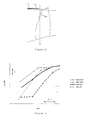
- Figure 14 is a graph showing the value of the noise cost function employed in the design process against non-dimensional mass flow (mrtp) for the datum blades CHK 000 and GEO2000 and their respective redesigned blades G578D4 and GEO2008.
- the redesigned blades clearly provide substantial noise reduction benefits (as quantified by the noise cost function) over their respective datum blades.
- FIG. 15a is a perspective view of the suction side of the GEOM2028 blade with the leading edge at the right
- Figure 15b is a perspective view of the pressure side of the blade with the leading edge at the left
- Figure 15c is a top view of the blade.
- Figure 16 is a graph showing the value of the noise cost function against non-dimensional mass flow (mrtp) for the GEO2000, GEO2008 and GEOM2028 blades, highlighting that the noise reduction persists over a range of operating conditions.
- Figure 17 is a sector of a transverse plane through the engine intake at the plane representative of the downstream end of the acoustic liner, and shows modelled contours of static pressure obtained from the CFD analysis of the GEO2000 datum blade.
- Figure 18 is a corresponding sector on the same plane from the CFD analysis of the GEOM2028 blade.
- feature A is an oblique shock extending from the leading edge of the GEO2000 blade
- Figure 18 shows two oblique shocks, B' and B ", extending from the leading edge of the GEOM2028 blade.
- the redesign of the blade has produced a different shock structure in which, upstream of the fan, the single oblique shock generated by the GEO2000 blade is replaced by two radially and circumferentially spaced shocks generated by the GEOM2028 blade. These two shocks are distinct and are separated by a region of static pressure gradient, C, which is less than that required to form a shock. In other blade designs, region C might take the form of a relatively weak shock connecting stronger shocks B' and B".
- the GEO2000 shock being radially relatively uniform, couples well to the first acoustic radial mode at the BPF of the intake duct.
- this mode is relatively poorly attenuated by the intake liner, and so leads to relatively high tone noise.
- the GEOM2028 shocks are out of phase with the first (that is, the least attenuated) lined radial mode at the BPF, and direct more acoustic power into higher, better attenuated, radial modes. The result is an overall reduction in radiated tone noise.
- Figure 19a is the same sector of transverse plane as Figure 18 and shows contours of constant pressure at the BPF (that is, when m is set to the number of fan blades) at a specific time t.
- Figures 19b-d then show contours of constant value for the three least attenuated radial modes p m ⁇ (r) under softwall conditions at the BPF. Maxima and minima are indicated in Figures 19a-d . What is clear is that Figure 19a is significantly more mismatched with Figure 19b , than with Figure 19c and d. As a consequence, more acoustic power at the BPF is directed into the more attenuated mode shown in Figure 19c than into the least attenuated mode shown in Figure 19b .
- Figure 20 is a graph of leading edge sweep angle plotted against radial distance from 0% span to 100% span for the GEOM2028 blade at the noise-critical take-off operating condition.
- the sweep angle variation which along with the blade stagger produces the double shock structure of Figure 18 and the pressure distribution of Figure 19a , is characterised by three turning points at about 52%, 82% and 94% span.
- the overall shape of the leading edge is more complicated than the shapes of the leading edges of conventional blades. For example, from the radially innermost to the radially outermost position, the leading edge has successive forward-rearward-forward-rearward-forward swept portions.
- the leading edge also has a high rearward sweep angle of about 56° at the 95% span position, before becoming forwardly swept at the blade tip. In reality the leading edge sweep angle for GEOM2028 blade would vary smoothly over the entire span.
- the apparent discontinuities in Figure 20 are modelling artefacts.
- Figure 21 is a graph of the acoustic powers at the BPF predicted ahead of the GEOM2028 and the datum GE02000 blades at the same operating point and with the same acoustic liner plotted against axial distance from the fan.
- the acoustic energies were calculated from a CFD analysis, including a soft-wall boundary condition to simulate the acoustic liner, to test the validity of the analytic liner model used in the blade design and optimise process. Close to the fan (at the right hand end of the graph) the acoustic power is similar for each blade. However, the modal content for the GEOM2028 blade is biased away from the first radial mode, which leads to a more effective attenuation of acoustic power by the liner and therefore less power remaining to be transmitted into the farfield.
- Figure 22 is a graph of the predicted upstream radiated rotor alone tone noise (in terms of sound power level PWL(dB)) at the BPF over a range of operating conditions (represented by differing back pressures) for the GEOM2028 and the GEO2000 blades.
- the greatest noise reduction is seen at the optimisation operating condition, but significant reductions are also obtained over a range of operating conditions.
Landscapes
- Engineering & Computer Science (AREA)
- Mechanical Engineering (AREA)
- General Engineering & Computer Science (AREA)
- Physics & Mathematics (AREA)
- Fluid Mechanics (AREA)
- Chemical & Material Sciences (AREA)
- Combustion & Propulsion (AREA)
- Structures Of Non-Positive Displacement Pumps (AREA)
Applications Claiming Priority (1)
| Application Number | Priority Date | Filing Date | Title |
|---|---|---|---|
| GBGB0701866.6A GB0701866D0 (en) | 2007-01-31 | 2007-01-31 | Tone noise reduction in turbomachines |
Publications (2)
| Publication Number | Publication Date |
|---|---|
| EP1953341A2 true EP1953341A2 (fr) | 2008-08-06 |
| EP1953341A3 EP1953341A3 (fr) | 2017-07-05 |
Family
ID=37891060
Family Applications (1)
| Application Number | Title | Priority Date | Filing Date |
|---|---|---|---|
| EP08250021.6A Withdrawn EP1953341A3 (fr) | 2007-01-31 | 2008-01-03 | Aube d'une turbomachine et procédé d'agencement |
Country Status (3)
| Country | Link |
|---|---|
| US (1) | US8177496B2 (fr) |
| EP (1) | EP1953341A3 (fr) |
| GB (1) | GB0701866D0 (fr) |
Cited By (5)
| Publication number | Priority date | Publication date | Assignee | Title |
|---|---|---|---|---|
| WO2012025359A1 (fr) | 2010-08-23 | 2012-03-01 | Rolls-Royce Plc | Procédé d'atténuation des vibrations d'une structure de profil aérodynamique et structure de profil aérodynamique correspondante |
| WO2012080669A1 (fr) | 2010-12-15 | 2012-06-21 | Snecma | Aube de turbomachine a loi d'empilage améliorée |
| FR2986285A1 (fr) * | 2012-01-30 | 2013-08-02 | Snecma | Aube pour soufflante de turboreacteur |
| EP2669475A1 (fr) * | 2012-06-01 | 2013-12-04 | Techspace Aero S.A. | Aube a profil en S de compresseur de turbomachine axiale, compresseur et turbomachine associée |
| EP3715586A1 (fr) * | 2019-03-27 | 2020-09-30 | Rolls-Royce Deutschland Ltd & Co KG | Pale d'aube de rotor d'une turbomachine |
Families Citing this family (53)
| Publication number | Priority date | Publication date | Assignee | Title |
|---|---|---|---|---|
| JP4923073B2 (ja) * | 2009-02-25 | 2012-04-25 | 株式会社日立製作所 | 遷音速翼 |
| GB0908128D0 (en) * | 2009-05-12 | 2009-06-24 | Rolls Royce Plc | An intake duct liner for a turbofan gas turbine engine |
| EP2476862B1 (fr) * | 2011-01-13 | 2013-11-20 | Alstom Technology Ltd | Aube statorique pour turbomachine à flux axial et turbomachine associée |
| US8684698B2 (en) | 2011-03-25 | 2014-04-01 | General Electric Company | Compressor airfoil with tip dihedral |
| US8702398B2 (en) | 2011-03-25 | 2014-04-22 | General Electric Company | High camber compressor rotor blade |
| US9115649B2 (en) | 2011-07-05 | 2015-08-25 | United Technologies Corporation | Fan stagger angle for dirt rejection |
| US9790797B2 (en) * | 2011-07-05 | 2017-10-17 | United Technologies Corporation | Subsonic swept fan blade |
| FR2993323B1 (fr) * | 2012-07-12 | 2014-08-15 | Snecma | Aube de turbomachine ayant un profil configure de maniere a obtenir des proprietes aerodynamiques et mecaniques ameliorees |
| US10233758B2 (en) | 2013-10-08 | 2019-03-19 | United Technologies Corporation | Detuning trailing edge compound lean contour |
| US9908170B2 (en) * | 2014-02-03 | 2018-03-06 | Indian Institute Of Technology, Bombay | Blade for axial compressor rotor |
| WO2015175052A2 (fr) | 2014-02-19 | 2015-11-19 | United Technologies Corporation | Profil aérodynamique de turbine à gaz |
| EP3108105B1 (fr) * | 2014-02-19 | 2021-05-12 | Raytheon Technologies Corporation | Surface portante pour turbine à gaz |
| US10570916B2 (en) | 2014-02-19 | 2020-02-25 | United Technologies Corporation | Gas turbine engine airfoil |
| WO2015175073A2 (fr) | 2014-02-19 | 2015-11-19 | United Technologies Corporation | Surface portante de moteur à turbine à gaz |
| EP3575551B1 (fr) | 2014-02-19 | 2021-10-27 | Raytheon Technologies Corporation | Surface portante de moteur à turbine à gaz |
| EP3108101B1 (fr) | 2014-02-19 | 2022-04-20 | Raytheon Technologies Corporation | Profil aérodynamique de moteur à turbine à gaz |
| WO2015175043A2 (fr) | 2014-02-19 | 2015-11-19 | United Technologies Corporation | Profil aérodynamique de moteur à turbine à gaz |
| EP3108103B1 (fr) | 2014-02-19 | 2023-09-27 | Raytheon Technologies Corporation | Aube de soufflante pour moteur à turbine à gaz |
| WO2015126454A1 (fr) | 2014-02-19 | 2015-08-27 | United Technologies Corporation | Surface portante de moteur à turbine à gaz |
| US10495106B2 (en) | 2014-02-19 | 2019-12-03 | United Technologies Corporation | Gas turbine engine airfoil |
| EP3108120B1 (fr) | 2014-02-19 | 2021-03-31 | Raytheon Technologies Corporation | Moteur à turbine à gaz ayant une architecture à engrenages et une structure à aube fixe spécifique |
| EP3108123B1 (fr) | 2014-02-19 | 2023-10-04 | Raytheon Technologies Corporation | Moteur à double flux à engrenage avec aubes de compresseur basse pression |
| EP3108100B1 (fr) * | 2014-02-19 | 2021-04-14 | Raytheon Technologies Corporation | Pale de soufflante de moteur à turbine à gaz |
| US10570915B2 (en) | 2014-02-19 | 2020-02-25 | United Technologies Corporation | Gas turbine engine airfoil |
| WO2015175044A2 (fr) | 2014-02-19 | 2015-11-19 | United Technologies Corporation | Profil aérodynamique de moteur à turbine à gaz |
| US10465702B2 (en) | 2014-02-19 | 2019-11-05 | United Technologies Corporation | Gas turbine engine airfoil |
| WO2015126941A1 (fr) | 2014-02-19 | 2015-08-27 | United Technologies Corporation | Profil aérodynamique de moteur à turbine à gaz |
| EP3985226B1 (fr) | 2014-02-19 | 2024-12-25 | RTX Corporation | Profil d'aube pour moteur à turbine à gaz |
| US9140127B2 (en) | 2014-02-19 | 2015-09-22 | United Technologies Corporation | Gas turbine engine airfoil |
| US10584715B2 (en) | 2014-02-19 | 2020-03-10 | United Technologies Corporation | Gas turbine engine airfoil |
| EP3108106B1 (fr) | 2014-02-19 | 2022-05-04 | Raytheon Technologies Corporation | Pale de moteur à turbine à gaz |
| US10208770B2 (en) * | 2014-02-24 | 2019-02-19 | Mitsubishi Electric Corporation | Axial flow fan |
| GB201404938D0 (en) * | 2014-03-19 | 2014-04-30 | Rolls Royce Plc | Fluidfoil fence |
| US10093152B2 (en) | 2014-06-09 | 2018-10-09 | Dometic Sweden Ab | Shrouded roof vent for a vehicle |
| EP3078448B1 (fr) * | 2015-04-10 | 2018-07-11 | Rolls-Royce Deutschland Ltd & Co KG | Procédé d'usinage d'un carter pour une turbomachine. |
| US9488129B1 (en) | 2015-05-13 | 2016-11-08 | King Fahd University Of Petroleum And Minerals | Passive edge-tone suppression method |
| US10400783B1 (en) * | 2015-07-01 | 2019-09-03 | Dometic Sweden Ab | Compact fan for a recreational vehicle |
| USD787037S1 (en) | 2015-07-01 | 2017-05-16 | Dometic Sweden Ab | Fan |
| GB2544735B (en) * | 2015-11-23 | 2018-02-07 | Rolls Royce Plc | Vanes of a gas turbine engine |
| GB2544554B (en) * | 2015-11-23 | 2018-07-04 | Rolls Royce Plc | Gas turbine engine |
| US11027595B2 (en) | 2016-10-13 | 2021-06-08 | Dometic Sweden Ab | Roof fan assembly |
| USD832987S1 (en) | 2016-10-13 | 2018-11-06 | Dometic Sweden Ab | Roof fan shroud |
| GB201702383D0 (en) * | 2017-02-14 | 2017-03-29 | Rolls Royce Plc | Gas turbine engine fan blade with axial lean |
| US10718214B2 (en) * | 2017-03-09 | 2020-07-21 | Honeywell International Inc. | High-pressure compressor rotor with leading edge having indent segment |
| CN107066761B (zh) * | 2017-05-16 | 2020-10-09 | 沈阳航空航天大学 | 一种电动飞机螺旋桨噪声计算方法 |
| US10808535B2 (en) * | 2018-09-27 | 2020-10-20 | General Electric Company | Blade structure for turbomachine |
| WO2020214470A1 (fr) * | 2019-04-19 | 2020-10-22 | Purdue Research Foundation | Utilisation de mesures de pression à réponse rapide pour surveiller de manière non intrusive des vibrations d'ailette dans des compresseurs axiaux |
| CN111859556B (zh) * | 2020-06-17 | 2022-08-09 | 中国航发湖南动力机械研究所 | 基于双四次Bezier曲面的离心叶轮设计方法及系统 |
| US11747236B2 (en) * | 2020-09-10 | 2023-09-05 | Virginia Tech Intellectual Properties, Inc. | Flow measurement for a gas turbine engine |
| GB202014210D0 (en) | 2020-09-10 | 2020-10-28 | Rolls Royce Plc | Gas turbine engine with airflow measurement system |
| US11821771B2 (en) | 2020-09-10 | 2023-11-21 | Virginia Tech Intellectual Properties, Inc. | Flow measurement for a gas turbine engine |
| US11796358B2 (en) | 2020-09-10 | 2023-10-24 | Virginia Tech Intellectual Properties, Inc. | Flow measurement for a gas turbine engine |
| CN113312706B (zh) * | 2021-06-15 | 2024-07-02 | 西北工业大学 | 一种涡轮叶片排干涉单音噪声准三维线化计算方法 |
Citations (3)
| Publication number | Priority date | Publication date | Assignee | Title |
|---|---|---|---|---|
| US5169288A (en) | 1991-09-06 | 1992-12-08 | General Electric Company | Low noise fan assembly |
| US6071077A (en) | 1996-04-09 | 2000-06-06 | Rolls-Royce Plc | Swept fan blade |
| US6358003B2 (en) | 1998-03-23 | 2002-03-19 | Rolls-Royce Deutschland Ltd & Co. Kg | Rotor blade an axial-flow engine |
Family Cites Families (10)
| Publication number | Priority date | Publication date | Assignee | Title |
|---|---|---|---|---|
| US3821999A (en) * | 1972-09-05 | 1974-07-02 | Mc Donnell Douglas Corp | Acoustic liner |
| US4012172A (en) | 1975-09-10 | 1977-03-15 | Avco Corporation | Low noise blades for axial flow compressors |
| GB2054058B (en) * | 1979-06-16 | 1983-04-20 | Rolls Royce | Reducing rotor noise |
| JP2000087898A (ja) | 1998-09-08 | 2000-03-28 | Matsushita Refrig Co Ltd | 軸流送風機 |
| JP2000161296A (ja) | 1998-11-20 | 2000-06-13 | Fujitsu I-Network Systems Ltd | 冷却用軸流ファン |
| US6328533B1 (en) * | 1999-12-21 | 2001-12-11 | General Electric Company | Swept barrel airfoil |
| JP3978083B2 (ja) * | 2001-06-12 | 2007-09-19 | 漢拏空調株式会社 | 軸流ファン |
| DE102004011607B4 (de) | 2004-03-10 | 2016-11-24 | MTU Aero Engines AG | Verdichter einer Gasturbine sowie Gasturbine |
| DE502004009528D1 (de) * | 2004-06-02 | 2009-07-09 | Rolls Royce Deutschland | Verdichterschaufel mit verminderter aerodynamischer Schaufelanregung |
| US7547186B2 (en) | 2004-09-28 | 2009-06-16 | Honeywell International Inc. | Nonlinearly stacked low noise turbofan stator |
-
2007
- 2007-01-31 GB GBGB0701866.6A patent/GB0701866D0/en not_active Ceased
-
2008
- 2008-01-03 EP EP08250021.6A patent/EP1953341A3/fr not_active Withdrawn
- 2008-01-16 US US12/007,828 patent/US8177496B2/en active Active
Patent Citations (3)
| Publication number | Priority date | Publication date | Assignee | Title |
|---|---|---|---|---|
| US5169288A (en) | 1991-09-06 | 1992-12-08 | General Electric Company | Low noise fan assembly |
| US6071077A (en) | 1996-04-09 | 2000-06-06 | Rolls-Royce Plc | Swept fan blade |
| US6358003B2 (en) | 1998-03-23 | 2002-03-19 | Rolls-Royce Deutschland Ltd & Co. Kg | Rotor blade an axial-flow engine |
Non-Patent Citations (3)
| Title |
|---|
| D. PRASAD; J. FENG: "Propagation and Decay of Shock Waves in Turbofan Engine Inlets", PROCEEDINGS OF ASME TURBO EXPO 2004, 14 June 2004 (2004-06-14) |
| J.M. TYLER; T.G. SOFRIN: "Axial Flow Compressor Noise Studies", SAE TRANSACTIONS, vol. 70, 1962, pages 309 - 332 |
| S. SHAHPAR; B.L. LAPWORTH: "PADRAM: Parametric Design and Rapid Meshing System for Turbomachinery Optimisation", ASME, 2003 |
Cited By (15)
| Publication number | Priority date | Publication date | Assignee | Title |
|---|---|---|---|---|
| WO2012025359A1 (fr) | 2010-08-23 | 2012-03-01 | Rolls-Royce Plc | Procédé d'atténuation des vibrations d'une structure de profil aérodynamique et structure de profil aérodynamique correspondante |
| CN103261700B (zh) * | 2010-12-15 | 2016-06-15 | 斯奈克玛 | 具有优化的积叠规律的涡轮发动机叶片 |
| WO2012080669A1 (fr) | 2010-12-15 | 2012-06-21 | Snecma | Aube de turbomachine a loi d'empilage améliorée |
| FR2969230A1 (fr) * | 2010-12-15 | 2012-06-22 | Snecma | Aube de compresseur a loi d'empilage amelioree |
| CN103261700A (zh) * | 2010-12-15 | 2013-08-21 | 斯奈克玛 | 具有优化的积叠规律的涡轮发动机叶片 |
| FR2986285A1 (fr) * | 2012-01-30 | 2013-08-02 | Snecma | Aube pour soufflante de turboreacteur |
| WO2013114030A1 (fr) * | 2012-01-30 | 2013-08-08 | Snecma | Aube pour soufflante de turboreacteur |
| US9695695B2 (en) | 2012-01-30 | 2017-07-04 | Snecma | Turbojet fan blade |
| CN104081005A (zh) * | 2012-01-30 | 2014-10-01 | 斯奈克玛 | 一种涡轮喷气发动机的风扇叶片 |
| EP2669475A1 (fr) * | 2012-06-01 | 2013-12-04 | Techspace Aero S.A. | Aube a profil en S de compresseur de turbomachine axiale, compresseur et turbomachine associée |
| RU2556481C2 (ru) * | 2012-06-01 | 2015-07-10 | Текспейс Аеро С.А. | Дозвуковая лопасть осевой турбомашины, компрессор осевой турбомашины и осевая турбомашина |
| CN103452904A (zh) * | 2012-06-01 | 2013-12-18 | 航空技术空间股份有限公司 | 用于轴向涡轮机压缩机的具有s形轮廓的叶片 |
| US9957973B2 (en) | 2012-06-01 | 2018-05-01 | Safran Aero Boosters Sa | Blade with an S-shaped profile for an axial turbomachine compressor |
| EP3715586A1 (fr) * | 2019-03-27 | 2020-09-30 | Rolls-Royce Deutschland Ltd & Co KG | Pale d'aube de rotor d'une turbomachine |
| US11499429B2 (en) | 2019-03-27 | 2022-11-15 | Rolls-Royce Deutschland Ltd & Co Kg | Rotor blade of a turbomachine |
Also Published As
| Publication number | Publication date |
|---|---|
| US8177496B2 (en) | 2012-05-15 |
| EP1953341A3 (fr) | 2017-07-05 |
| GB0701866D0 (en) | 2007-03-14 |
| US20080181769A1 (en) | 2008-07-31 |
Similar Documents
| Publication | Publication Date | Title |
|---|---|---|
| US8177496B2 (en) | Tone noise reduction in turbomachines | |
| Envia | Fan noise reduction: an overview | |
| Doherty et al. | Impact of turbofan intake distortion on fan noise propagation and generation | |
| Lee et al. | Numerical study on aeroelastic instability for a low speed fan | |
| Mehdi | Effect of swirl distortion on gas turbine operability | |
| Lu et al. | Simulation and experimental research on aerodynamic noise of gas turbine 1.5-stage axial compressor | |
| CN113868900B (zh) | 基于流场尾迹的低噪声设计和评估方法 | |
| Xiong et al. | Effects of turbofan engine intake droop and length on fan tone noise | |
| Huff | Fan noise prediction-status and needs | |
| Svetgoff et al. | Inlet Radiated Noise Predictions for the NASA Source Diagnostic Test Fan Using Physics-Based Simulations | |
| Moreau et al. | A fast prediction method for rotor buzz-saw noise based on an analytical approach | |
| Milidonis et al. | The effect of steady intake distortion on Fan MPT Noise under sideline flight conditions | |
| Wu et al. | Fan Buzz-Saw Noise under Intake Flow Distortion: a Computational Study | |
| Stephens et al. | Acoustic Simulations of Two-stage Fans Behind a Supersonic Inlet | |
| CN118378371A (zh) | 一种燃气轮机排气系统降噪装置的设计方法 | |
| Salze et al. | Noise reduction of aero-engines using innovative stators with leading edge features | |
| Stapelfeldt et al. | On the importance of engine-representative models for fan flutter predictions | |
| Dai | Modelling Considerations for a Transonic Fan | |
| Xue et al. | Study of noise reduction based on optimal fan outer pressure ratio and thermodynamic performance for turbofan engines at conceptual design stage | |
| Lewy | Prediction of turbofan rotor or stator broadband noise radiation | |
| Binns et al. | Part-Span Approximation of Tone Noise Propagation in an Aeroengine Intake. Part 2: Non-Linear Propagation | |
| Tang et al. | Prediction of “buzz-saw” noise propagation under nonuniform axial and radial flows | |
| Druzhinin et al. | Numerical and experimental investigation of aerodynamic characteristics of model ultra high bypass ratio counter rotating fan | |
| Druzhinin et al. | Computational investigation of aerodynamic and acoustic characteristics of counter rotating fan with ultra high bypass ratio | |
| Moreau et al. | Development and application of a new procedure for fan noise prediction |
Legal Events
| Date | Code | Title | Description |
|---|---|---|---|
| PUAI | Public reference made under article 153(3) epc to a published international application that has entered the european phase |
Free format text: ORIGINAL CODE: 0009012 |
|
| AK | Designated contracting states |
Kind code of ref document: A2 Designated state(s): AT BE BG CH CY CZ DE DK EE ES FI FR GB GR HR HU IE IS IT LI LT LU LV MC MT NL NO PL PT RO SE SI SK TR |
|
| AX | Request for extension of the european patent |
Extension state: AL BA MK RS |
|
| RAP1 | Party data changed (applicant data changed or rights of an application transferred) |
Owner name: ROLLS-ROYCE PLC |
|
| RIC1 | Information provided on ipc code assigned before grant |
Ipc: F04D 29/32 20060101ALI20170419BHEP Ipc: F02K 3/06 20060101ALI20170419BHEP Ipc: F01D 5/16 20060101ALI20170419BHEP Ipc: F04D 21/00 20060101ALI20170419BHEP Ipc: F01D 5/14 20060101AFI20170419BHEP |
|
| PUAL | Search report despatched |
Free format text: ORIGINAL CODE: 0009013 |
|
| RIC1 | Information provided on ipc code assigned before grant |
Ipc: F01D 5/16 20060101ALI20170524BHEP Ipc: F01D 5/14 20060101AFI20170524BHEP Ipc: F04D 29/32 20060101ALI20170524BHEP Ipc: F02K 3/06 20060101ALI20170524BHEP Ipc: F04D 21/00 20060101ALI20170524BHEP |
|
| AK | Designated contracting states |
Kind code of ref document: A3 Designated state(s): AT BE BG CH CY CZ DE DK EE ES FI FR GB GR HR HU IE IS IT LI LT LU LV MC MT NL NO PL PT RO SE SI SK TR |
|
| AX | Request for extension of the european patent |
Extension state: AL BA MK RS |
|
| 17P | Request for examination filed |
Effective date: 20171222 |
|
| RBV | Designated contracting states (corrected) |
Designated state(s): AT BE BG CH CY CZ DE DK EE ES FI FR GB GR HR HU IE IS IT LI LT LU LV MC MT NL NO PL PT RO SE SI SK TR |
|
| AKX | Designation fees paid |
Designated state(s): AT BE BG CH CY CZ DE DK EE ES FI FR GB GR HR HU IE IS IT LI LT LU LV MC MT NL NO PL PT RO SE SI SK TR |
|
| AXX | Extension fees paid |
Extension state: MK Extension state: BA Extension state: AL Extension state: RS |
|
| 17Q | First examination report despatched |
Effective date: 20180709 |
|
| STAA | Information on the status of an ep patent application or granted ep patent |
Free format text: STATUS: THE APPLICATION IS DEEMED TO BE WITHDRAWN |
|
| 18D | Application deemed to be withdrawn |
Effective date: 20190608 |