EP1953343A2 - Système de refroidissement d'une aube de turbine à gaz et aube de turbine à gaz associée - Google Patents
Système de refroidissement d'une aube de turbine à gaz et aube de turbine à gaz associée Download PDFInfo
- Publication number
- EP1953343A2 EP1953343A2 EP08250187A EP08250187A EP1953343A2 EP 1953343 A2 EP1953343 A2 EP 1953343A2 EP 08250187 A EP08250187 A EP 08250187A EP 08250187 A EP08250187 A EP 08250187A EP 1953343 A2 EP1953343 A2 EP 1953343A2
- Authority
- EP
- European Patent Office
- Prior art keywords
- cavity
- cooling
- cooling system
- side wall
- airfoil portion
- Prior art date
- Legal status (The legal status is an assumption and is not a legal conclusion. Google has not performed a legal analysis and makes no representation as to the accuracy of the status listed.)
- Granted
Links
Images

Classifications
-
- F—MECHANICAL ENGINEERING; LIGHTING; HEATING; WEAPONS; BLASTING
- F01—MACHINES OR ENGINES IN GENERAL; ENGINE PLANTS IN GENERAL; STEAM ENGINES
- F01D—NON-POSITIVE DISPLACEMENT MACHINES OR ENGINES, e.g. STEAM TURBINES
- F01D5/00—Blades; Blade-carrying members; Heating, heat-insulating, cooling or antivibration means on the blades or the members
- F01D5/12—Blades
- F01D5/14—Form or construction
- F01D5/18—Hollow blades, i.e. blades with cooling or heating channels or cavities; Heating, heat-insulating or cooling means on blades
- F01D5/186—Film cooling
-
- F—MECHANICAL ENGINEERING; LIGHTING; HEATING; WEAPONS; BLASTING
- F01—MACHINES OR ENGINES IN GENERAL; ENGINE PLANTS IN GENERAL; STEAM ENGINES
- F01D—NON-POSITIVE DISPLACEMENT MACHINES OR ENGINES, e.g. STEAM TURBINES
- F01D5/00—Blades; Blade-carrying members; Heating, heat-insulating, cooling or antivibration means on the blades or the members
- F01D5/12—Blades
- F01D5/14—Form or construction
- F01D5/18—Hollow blades, i.e. blades with cooling or heating channels or cavities; Heating, heat-insulating or cooling means on blades
- F01D5/187—Convection cooling
-
- F—MECHANICAL ENGINEERING; LIGHTING; HEATING; WEAPONS; BLASTING
- F05—INDEXING SCHEMES RELATING TO ENGINES OR PUMPS IN VARIOUS SUBCLASSES OF CLASSES F01-F04
- F05D—INDEXING SCHEME FOR ASPECTS RELATING TO NON-POSITIVE-DISPLACEMENT MACHINES OR ENGINES, GAS-TURBINES OR JET-PROPULSION PLANTS
- F05D2240/00—Components
- F05D2240/10—Stators
- F05D2240/12—Fluid guiding means, e.g. vanes
- F05D2240/122—Fluid guiding means, e.g. vanes related to the trailing edge of a stator vane
-
- F—MECHANICAL ENGINEERING; LIGHTING; HEATING; WEAPONS; BLASTING
- F05—INDEXING SCHEMES RELATING TO ENGINES OR PUMPS IN VARIOUS SUBCLASSES OF CLASSES F01-F04
- F05D—INDEXING SCHEME FOR ASPECTS RELATING TO NON-POSITIVE-DISPLACEMENT MACHINES OR ENGINES, GAS-TURBINES OR JET-PROPULSION PLANTS
- F05D2240/00—Components
- F05D2240/20—Rotors
- F05D2240/30—Characteristics of rotor blades, i.e. of any element transforming dynamic fluid energy to or from rotational energy and being attached to a rotor
- F05D2240/304—Characteristics of rotor blades, i.e. of any element transforming dynamic fluid energy to or from rotational energy and being attached to a rotor related to the trailing edge of a rotor blade
-
- F—MECHANICAL ENGINEERING; LIGHTING; HEATING; WEAPONS; BLASTING
- F05—INDEXING SCHEMES RELATING TO ENGINES OR PUMPS IN VARIOUS SUBCLASSES OF CLASSES F01-F04
- F05D—INDEXING SCHEME FOR ASPECTS RELATING TO NON-POSITIVE-DISPLACEMENT MACHINES OR ENGINES, GAS-TURBINES OR JET-PROPULSION PLANTS
- F05D2260/00—Function
- F05D2260/20—Heat transfer, e.g. cooling
- F05D2260/202—Heat transfer, e.g. cooling by film cooling
Definitions
- the present invention relates to a trailing edge cooling design for an airfoil portion of a turbine engine component.
- FIG. 1 illustrates a conventional turbine blade 10 having a single cutback trailing edge.
- the airfoil portion 12 of the blade 10 has a cooling scheme which attempts to cool the very trailing edge 14 as well as the aft pressure side of the airfoil portion 12 with the same set of cast features. That is, the cooling air passes through a first row of cross-over holes 18 and a second row of cross-over holes 20 and finally into the cut back slot 23.
- the cavity 22 between the rows 18 and 20 of cross-over holes is also a source of cooling air for the pressure side of the airfoil portion 12 via one or more rows of cooling film holes 24. The cooling air flowing from the film holes 24 is used to cool the pressure side slot lip 16.
- the cavity 22 is a difficult area in which to predict internal pressures. It is sensitive to cross-over geometry and the drilling tolerances of the holes 24. Balancing the flow between cooling the very trailing edge 14 of the airfoil portion 12 and the pressure side lip 16 can be very difficult, given the existence of small aerodynamic wedge angles, and the casting tolerances on the cross-over holes 18 and 20.
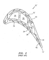
- FIG. 2 illustrates another airfoil portion 12' of a turbine engine blade 10' having a single cutback trailing edge.
- this type of turbine engine blade there are cooling air supply cavities 30 and 32.
- a plurality of supply cavities 34 are formed in the walls of the airfoil portion 12'.
- Each supply cavity 34 receives cooling fluid from the root of the.airfoil and/or from one of the supply cavities 30 and 32.
- At least some of the supply cavities 34 cooperate with a series of film cooling holes 36 to create a film of cooling fluid over one of the pressure side 38 and the suction side 40 of the airfoil portion 12'.
- a trailing edge cutback slot 42 is formed in the airfoil portion 12'.
- the cutback slot 42 receives cooling fluid from a cavity 44.
- a cooling system for an airfoil portion of a turbine engine component which cooling system includes a first cavity dedicated to cooling a trailing edge portion of an airfoil portion and a second cavity dedicated to cooling an aft portion of a pressure side wall of the airfoil portion.
- a turbine engine component broadly comprising an airfoil portion having a trailing edge, a first cavity adjacent a suction side wall for cooling said trailing edge, and a second cavity adjacent a pressure side wall for cooling an aft portion of the pressure side wall.
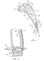
- FIG. 3 illustrates an airfoil portion 112 of a turbine engine component, such as a turbine blade or vane.
- the turbine engine component may have a platform 100 and a root portion 102.
- the airfoil portion 112 has a pressure side wall 114, a suction side wall 116 and a trailing edge 118.
- the airfoil portion 112 has a plurality of cooling fluid supply cavities 120, 122, 124, 126, 128, 130, and 132.
- the supply cavity 120 feeds a plurality of cooling holes 134 for cooling the leading edge 136 of the airfoil portion 112.
- the supply cavities 122, 124, and 126 feed a plurality of film cooling holes 138 for flowing a film of cooling fluid over the suction side of the airfoil portion 112.
- the supply cavities 124, 126, 128, 130, and 132 supply cooling fluid to a plurality of film cooling holes 140 for flowing a film of cooling fluid over the pressure side of the airfoil portion 112. While only one row of film cooling holes 134, 138, and 140 have been depicted in FIG. 3 , it should be understood that there are actually rows of film cooling holes 134, 138, 140 along the span of the airfoil portion 112.
- a first dedicated trailing edge cavity or passageway 142 is fabricated in the airfoil portion 112.
- the trailing edge cavity 142 is fed with cooling fluid from the supply cavity 132.
- the trailing edge cavity 142 has a plurality of slots 143 through which the cooling fluid exits and flows over the trailing edge.
- a second dedicated trailing edge cavity or passageway 146 is fabricated in the airfoil portion 112.
- the second dedicated trailing edge cavity 146 is separated from the first dedicated trailing edge cavity 142 by a cast wall structure 148.
- the trailing edge cavity 146 is supplied with cooling fluid from the supply cavity 132.
- the trailing edge cavity 146 has a plurality of slots 150 through which the cooling fluid exits and flows over the aft portion 144 of the pressure side wall 114.
- the slots 150 may be offset with respect to the slots 143. Further, the row of slots 143 and/or the row of slots 150 may be fanned to conform to the streamlines of the fluid flowing over the airfoil portion 112.
- first dedicated trailing edge cavity 142 may be in communication with the second dedicated trailing edge cavity 146 via one or more crossover holes 145.
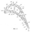
- FIG. 5 illustrates another blade configuration having an airfoil portion 212 with a pressure side wall 214, a suction side wall 216, and a trailing edge 218.
- the airfoil portion has a supply cavity 220, a supply cavity 222, and a main supply cavity 224.
- the supply cavity 220 may be used to supply cooling fluid to one or more leading edge cooling holes 234 for causing cooling fluid to flow over the leading edge 236 of the airfoil portion 212.
- a plurality of cooling circuits 260 are fabricated into the pressure side wall 214 and the suction side wall 216.
- the cooling circuits 260 may have any desired configuration and may be fabricated using any suitable technology known in the art.
- One or more of the cooling circuits 260 embedded within the suction side wall 216 may communicate with one or more film cooling holes 262.
- a plurality of the cooling circuits 260 embedded within the pressure side wall 214 may communicate with one or more film cooling holes 266.
- the cooling circuits 260 may be supplied with cooling fluid from the root of the airfoil portion and/or from one of the supply cavities 222 and 224 via passageways.
- a feed cavity 270 may be fabricated into the pressure side wall 214 and may be supplied with cooling fluid via one or more cross over holes 272.
- a first trailing edge cavity or passageway 242 may be formed in the airfoil portion 212.
- the trailing edge cavity 242 receives cooling fluid from a supply cavity 274 which is in communication with supply cavity 224.
- the trailing edge cavity 242 may terminate in a plurality of slots 243 which may be arranged in a row.
- a second trailing edge cavity or passageway 246 may be formed in the airfoil portion 212.
- the second trailing edge cavity receives cooling fluid from the feed cavity 270.
- the trailing edge cavity 246 may terminate in a plurality of slots 250 which may be configured in a row. As before, the slots 250 and 243 may be offset so as to promote cooling film coverage. Additionally, one or more of rows of slots 243 and 250 may be fanned to conform to the streamlines of the fluid flowing over the airfoil portion 212.
- the trailing edge cavities 142, 146, 242, and 246 may be formed using a ceramic core or a refractory metal core or any other suitable manufacturing technology known in the art.
- cooler trailing edge temperatures may be achieved. Additionally, one may be able to use lower trailing edge wedge angles for better aerodynamic efficiency. Still further, backflow margin issues normally associated with film rows may be minimized. Using the slot arrangement described herein will improve film/cooling effectiveness by increasing coverage.
Landscapes
- Engineering & Computer Science (AREA)
- Mechanical Engineering (AREA)
- General Engineering & Computer Science (AREA)
- Turbine Rotor Nozzle Sealing (AREA)
Applications Claiming Priority (1)
| Application Number | Priority Date | Filing Date | Title |
|---|---|---|---|
| US11/657,322 US7845906B2 (en) | 2007-01-24 | 2007-01-24 | Dual cut-back trailing edge for airfoils |
Publications (3)
| Publication Number | Publication Date |
|---|---|
| EP1953343A2 true EP1953343A2 (fr) | 2008-08-06 |
| EP1953343A3 EP1953343A3 (fr) | 2011-02-02 |
| EP1953343B1 EP1953343B1 (fr) | 2013-02-27 |
Family
ID=39154149
Family Applications (1)
| Application Number | Title | Priority Date | Filing Date |
|---|---|---|---|
| EP08250187A Revoked EP1953343B1 (fr) | 2007-01-24 | 2008-01-15 | Système de refroidissement d'une aube de turbine à gaz et aube de turbine à gaz associée |
Country Status (2)
| Country | Link |
|---|---|
| US (1) | US7845906B2 (fr) |
| EP (1) | EP1953343B1 (fr) |
Cited By (7)
| Publication number | Priority date | Publication date | Assignee | Title |
|---|---|---|---|---|
| EP1959097A3 (fr) * | 2007-02-16 | 2014-04-16 | United Technologies Corporation | Refroidissement peau-noyau par contact pour une pale de moteur à turbine à gaz |
| EP2733309A1 (fr) * | 2012-11-16 | 2014-05-21 | Siemens Aktiengesellschaft | Aube de turbine avec dispositif de refroidissement |
| EP2754856A1 (fr) * | 2013-01-09 | 2014-07-16 | Siemens Aktiengesellschaft | Pale pour turbomachine |
| EP3106616B1 (fr) | 2015-05-08 | 2018-04-18 | United Technologies Corporation | Passage de refroidissement du noyau de peau axial d'un composant de moteur à turbine |
| EP3399148A1 (fr) * | 2017-05-02 | 2018-11-07 | United Technologies Corporation | Aube refroidie pour un moteur à turbine à gaz |
| US10502066B2 (en) | 2015-05-08 | 2019-12-10 | United Technologies Corporation | Turbine engine component including an axially aligned skin core passage interrupted by a pedestal |
| FR3102794A1 (fr) * | 2019-10-31 | 2021-05-07 | Safran Aircraft Engines | Composant de turbomachine comportant des orifices de refroidissement ameliores |
Families Citing this family (50)
| Publication number | Priority date | Publication date | Assignee | Title |
|---|---|---|---|---|
| US8105033B2 (en) * | 2008-06-05 | 2012-01-31 | United Technologies Corporation | Particle resistant in-wall cooling passage inlet |
| US8398370B1 (en) * | 2009-09-18 | 2013-03-19 | Florida Turbine Technologies, Inc. | Turbine blade with multi-impingement cooling |
| US8511994B2 (en) * | 2009-11-23 | 2013-08-20 | United Technologies Corporation | Serpentine cored airfoil with body microcircuits |
| JP2012189026A (ja) * | 2011-03-11 | 2012-10-04 | Ihi Corp | タービン翼 |
| US8714927B1 (en) * | 2011-07-12 | 2014-05-06 | United Technologies Corporation | Microcircuit skin core cut back to reduce microcircuit trailing edge stresses |
| US20130052037A1 (en) * | 2011-08-31 | 2013-02-28 | William Abdel-Messeh | Airfoil with nonlinear cooling passage |
| US8992179B2 (en) | 2011-10-28 | 2015-03-31 | General Electric Company | Turbine of a turbomachine |
| US9255480B2 (en) | 2011-10-28 | 2016-02-09 | General Electric Company | Turbine of a turbomachine |
| US8967959B2 (en) | 2011-10-28 | 2015-03-03 | General Electric Company | Turbine of a turbomachine |
| US9051843B2 (en) * | 2011-10-28 | 2015-06-09 | General Electric Company | Turbomachine blade including a squeeler pocket |
| US9273566B2 (en) | 2012-06-22 | 2016-03-01 | United Technologies Corporation | Turbine engine variable area vane |
| US9103222B2 (en) | 2012-06-22 | 2015-08-11 | United Technologies Corporation | Turbine engine variable area vane with feather seal |
| US9115590B2 (en) * | 2012-09-26 | 2015-08-25 | United Technologies Corporation | Gas turbine engine airfoil cooling circuit |
| JP6038620B2 (ja) * | 2012-12-05 | 2016-12-07 | 三菱日立パワーシステムズ株式会社 | ガスタービン冷却翼およびガスタービン冷却翼の補修方法 |
| US9790801B2 (en) | 2012-12-27 | 2017-10-17 | United Technologies Corporation | Gas turbine engine component having suction side cutback opening |
| US10215048B2 (en) | 2013-01-21 | 2019-02-26 | United Technologies Corporation | Variable area vane arrangement for a turbine engine |
| US9464528B2 (en) | 2013-06-14 | 2016-10-11 | Solar Turbines Incorporated | Cooled turbine blade with double compound angled holes and slots |
| WO2015009448A1 (fr) * | 2013-07-19 | 2015-01-22 | United Technologies Corporation | Noyau réalisé par fabrication additive |
| US20150184538A1 (en) * | 2013-12-30 | 2015-07-02 | General Electric Company | Interior cooling circuits in turbine blades |
| US10119405B2 (en) * | 2015-12-21 | 2018-11-06 | General Electric Company | Cooling circuit for a multi-wall blade |
| US10060269B2 (en) | 2015-12-21 | 2018-08-28 | General Electric Company | Cooling circuits for a multi-wall blade |
| US10053989B2 (en) | 2015-12-21 | 2018-08-21 | General Electric Company | Cooling circuit for a multi-wall blade |
| US10030526B2 (en) | 2015-12-21 | 2018-07-24 | General Electric Company | Platform core feed for a multi-wall blade |
| US9909427B2 (en) | 2015-12-22 | 2018-03-06 | General Electric Company | Turbine airfoil with trailing edge cooling circuit |
| US9938836B2 (en) | 2015-12-22 | 2018-04-10 | General Electric Company | Turbine airfoil with trailing edge cooling circuit |
| EP3192970A1 (fr) | 2016-01-15 | 2017-07-19 | General Electric Technology GmbH | Aube de turbine à gaz et procédé de fabrication |
| FR3048718B1 (fr) * | 2016-03-10 | 2020-01-24 | Safran | Aube de turbomachine a refroidissement optimise |
| US10221696B2 (en) | 2016-08-18 | 2019-03-05 | General Electric Company | Cooling circuit for a multi-wall blade |
| US10208607B2 (en) | 2016-08-18 | 2019-02-19 | General Electric Company | Cooling circuit for a multi-wall blade |
| US10208608B2 (en) | 2016-08-18 | 2019-02-19 | General Electric Company | Cooling circuit for a multi-wall blade |
| US10267162B2 (en) | 2016-08-18 | 2019-04-23 | General Electric Company | Platform core feed for a multi-wall blade |
| US10227877B2 (en) | 2016-08-18 | 2019-03-12 | General Electric Company | Cooling circuit for a multi-wall blade |
| US10450950B2 (en) | 2016-10-26 | 2019-10-22 | General Electric Company | Turbomachine blade with trailing edge cooling circuit |
| US10301946B2 (en) * | 2016-10-26 | 2019-05-28 | General Electric Company | Partially wrapped trailing edge cooling circuits with pressure side impingements |
| US10309227B2 (en) | 2016-10-26 | 2019-06-04 | General Electric Company | Multi-turn cooling circuits for turbine blades |
| US10598028B2 (en) | 2016-10-26 | 2020-03-24 | General Electric Company | Edge coupon including cooling circuit for airfoil |
| US10352176B2 (en) | 2016-10-26 | 2019-07-16 | General Electric Company | Cooling circuits for a multi-wall blade |
| US10240465B2 (en) | 2016-10-26 | 2019-03-26 | General Electric Company | Cooling circuits for a multi-wall blade |
| US10465521B2 (en) | 2016-10-26 | 2019-11-05 | General Electric Company | Turbine airfoil coolant passage created in cover |
| US10450875B2 (en) | 2016-10-26 | 2019-10-22 | General Electric Company | Varying geometries for cooling circuits of turbine blades |
| US10273810B2 (en) | 2016-10-26 | 2019-04-30 | General Electric Company | Partially wrapped trailing edge cooling circuit with pressure side serpentine cavities |
| US10233761B2 (en) | 2016-10-26 | 2019-03-19 | General Electric Company | Turbine airfoil trailing edge coolant passage created by cover |
| US10753210B2 (en) * | 2018-05-02 | 2020-08-25 | Raytheon Technologies Corporation | Airfoil having improved cooling scheme |
| CN209324436U (zh) * | 2019-02-14 | 2019-08-30 | 高晟钧 | 一种航空发动机涡轮叶片 |
| CN109973154B (zh) * | 2019-04-02 | 2019-12-06 | 高晟钧 | 一种带有冷却结构的航空发动机涡轮叶片 |
| US11814965B2 (en) | 2021-11-10 | 2023-11-14 | General Electric Company | Turbomachine blade trailing edge cooling circuit with turn passage having set of obstructions |
| CN116792161B (zh) * | 2022-03-14 | 2026-04-10 | 中国航发商用航空发动机有限责任公司 | 翼型件 |
| CN114673687B (zh) * | 2022-05-30 | 2022-08-19 | 长城汽车股份有限公司 | 扇叶总成、风扇及车辆 |
| US12065944B1 (en) * | 2023-03-07 | 2024-08-20 | Rtx Corporation | Airfoils with mixed skin passageway cooling |
| US12540552B2 (en) | 2023-03-07 | 2026-02-03 | Rtx Corporation | Airfoils with axial leading edge impingement slots |
Citations (5)
| Publication number | Priority date | Publication date | Assignee | Title |
|---|---|---|---|---|
| US5215431A (en) | 1991-06-25 | 1993-06-01 | Societe Nationale D'etude Et De Construction De Moteurs D'aviation "S.N.E.C.M.A." | Cooled turbine guide vane |
| US6126397A (en) | 1998-12-22 | 2000-10-03 | United Technologies Corporation | Trailing edge cooling apparatus for a gas turbine airfoil |
| US20030059305A1 (en) | 2001-06-14 | 2003-03-27 | Rolls-Royce Plc | Air cooled aerofoil |
| US20050106022A1 (en) | 2003-11-13 | 2005-05-19 | Macmanus David G. | Vorticity control in a gas turbine engine |
| US6981840B2 (en) | 2003-10-24 | 2006-01-03 | General Electric Company | Converging pin cooled airfoil |
Family Cites Families (6)
| Publication number | Priority date | Publication date | Assignee | Title |
|---|---|---|---|---|
| US5503529A (en) * | 1994-12-08 | 1996-04-02 | General Electric Company | Turbine blade having angled ejection slot |
| US5458461A (en) * | 1994-12-12 | 1995-10-17 | General Electric Company | Film cooled slotted wall |
| US6164913A (en) * | 1999-07-26 | 2000-12-26 | General Electric Company | Dust resistant airfoil cooling |
| US7374401B2 (en) * | 2005-03-01 | 2008-05-20 | General Electric Company | Bell-shaped fan cooling holes for turbine airfoil |
| US7549844B2 (en) * | 2006-08-24 | 2009-06-23 | Siemens Energy, Inc. | Turbine airfoil cooling system with bifurcated and recessed trailing edge exhaust channels |
| US7871246B2 (en) | 2007-02-15 | 2011-01-18 | Siemens Energy, Inc. | Airfoil for a gas turbine |
-
2007
- 2007-01-24 US US11/657,322 patent/US7845906B2/en active Active
-
2008
- 2008-01-15 EP EP08250187A patent/EP1953343B1/fr not_active Revoked
Patent Citations (5)
| Publication number | Priority date | Publication date | Assignee | Title |
|---|---|---|---|---|
| US5215431A (en) | 1991-06-25 | 1993-06-01 | Societe Nationale D'etude Et De Construction De Moteurs D'aviation "S.N.E.C.M.A." | Cooled turbine guide vane |
| US6126397A (en) | 1998-12-22 | 2000-10-03 | United Technologies Corporation | Trailing edge cooling apparatus for a gas turbine airfoil |
| US20030059305A1 (en) | 2001-06-14 | 2003-03-27 | Rolls-Royce Plc | Air cooled aerofoil |
| US6981840B2 (en) | 2003-10-24 | 2006-01-03 | General Electric Company | Converging pin cooled airfoil |
| US20050106022A1 (en) | 2003-11-13 | 2005-05-19 | Macmanus David G. | Vorticity control in a gas turbine engine |
Cited By (15)
| Publication number | Priority date | Publication date | Assignee | Title |
|---|---|---|---|---|
| EP1959097A3 (fr) * | 2007-02-16 | 2014-04-16 | United Technologies Corporation | Refroidissement peau-noyau par contact pour une pale de moteur à turbine à gaz |
| US9702256B2 (en) | 2012-11-16 | 2017-07-11 | Siemens Aktiengesellschaft | Turbine blade with cooling arrangement |
| EP2733309A1 (fr) * | 2012-11-16 | 2014-05-21 | Siemens Aktiengesellschaft | Aube de turbine avec dispositif de refroidissement |
| WO2014075895A1 (fr) | 2012-11-16 | 2014-05-22 | Siemens Aktiengesellschaft | Aube de turbine à système de refroidissement |
| US9909426B2 (en) | 2013-01-09 | 2018-03-06 | Siemens Aktiengesellschaft | Blade for a turbomachine |
| WO2014108318A1 (fr) * | 2013-01-09 | 2014-07-17 | Siemens Aktiengesellschaft | Pale pour une turbomachine |
| EP2754856A1 (fr) * | 2013-01-09 | 2014-07-16 | Siemens Aktiengesellschaft | Pale pour turbomachine |
| RU2659597C2 (ru) * | 2013-01-09 | 2018-07-03 | Сименс Акциенгезелльшафт | Лопатка для турбомашины |
| EP3106616B1 (fr) | 2015-05-08 | 2018-04-18 | United Technologies Corporation | Passage de refroidissement du noyau de peau axial d'un composant de moteur à turbine |
| US10323524B2 (en) | 2015-05-08 | 2019-06-18 | United Technologies Corporation | Axial skin core cooling passage for a turbine engine component |
| US10502066B2 (en) | 2015-05-08 | 2019-12-10 | United Technologies Corporation | Turbine engine component including an axially aligned skin core passage interrupted by a pedestal |
| US11143039B2 (en) | 2015-05-08 | 2021-10-12 | Raytheon Technologies Corporation | Turbine engine component including an axially aligned skin core passage interrupted by a pedestal |
| EP3399148A1 (fr) * | 2017-05-02 | 2018-11-07 | United Technologies Corporation | Aube refroidie pour un moteur à turbine à gaz |
| US11098595B2 (en) | 2017-05-02 | 2021-08-24 | Raytheon Technologies Corporation | Airfoil for gas turbine engine |
| FR3102794A1 (fr) * | 2019-10-31 | 2021-05-07 | Safran Aircraft Engines | Composant de turbomachine comportant des orifices de refroidissement ameliores |
Also Published As
| Publication number | Publication date |
|---|---|
| US7845906B2 (en) | 2010-12-07 |
| EP1953343B1 (fr) | 2013-02-27 |
| EP1953343A3 (fr) | 2011-02-02 |
| US20080175714A1 (en) | 2008-07-24 |
Similar Documents
| Publication | Publication Date | Title |
|---|---|---|
| EP1953343B1 (fr) | Système de refroidissement d'une aube de turbine à gaz et aube de turbine à gaz associée | |
| US6283708B1 (en) | Coolable vane or blade for a turbomachine | |
| US7980821B1 (en) | Turbine blade with trailing edge cooling | |
| US7997866B2 (en) | Gas turbine airfoil with leading edge cooling | |
| US7641444B1 (en) | Serpentine flow circuit with tip section cooling channels | |
| US7845907B2 (en) | Blade cooling passage for a turbine engine | |
| EP1882816B1 (fr) | Microcircuit de refroidissement serpentin divisé radialement | |
| US8197211B1 (en) | Composite air cooled turbine rotor blade | |
| US8011888B1 (en) | Turbine blade with serpentine cooling | |
| EP0971095B1 (fr) | Aube refroidissable pour turbines à gaz | |
| US7527475B1 (en) | Turbine blade with a near-wall cooling circuit | |
| US20160097286A1 (en) | Internal cooling of engine components | |
| US8616845B1 (en) | Turbine blade with tip cooling circuit | |
| US8398370B1 (en) | Turbine blade with multi-impingement cooling | |
| US9279331B2 (en) | Gas turbine engine airfoil with dirt purge feature and core for making same | |
| US7704045B1 (en) | Turbine blade with blade tip cooling notches | |
| EP2912274B1 (fr) | Agencement de refroidissement pour élément de turbine à gaz | |
| JP4801513B2 (ja) | ターボ機械の可動な翼のための冷却回路 | |
| EP1801351A2 (fr) | Refroidissement de pointe d'aube de turbine | |
| EP2911815B1 (fr) | Noyau de coulée pour un arrangement de refroidissement pour un élément de turbine à gaz | |
| US8052390B1 (en) | Turbine airfoil with showerhead cooling | |
| EP2267276B1 (fr) | Aube avec un bord de fuite hybride foré et coupé et procédé de refroidissement d'une telle aube | |
| EP1676981A3 (fr) | Refroidissement d'une virole de turbine | |
| WO2018182816A1 (fr) | Profil de turbine à circuit de refroidissement de bord de fuite mince | |
| US7661930B2 (en) | Central cooling circuit for a moving blade of a turbomachine |
Legal Events
| Date | Code | Title | Description |
|---|---|---|---|
| PUAI | Public reference made under article 153(3) epc to a published international application that has entered the european phase |
Free format text: ORIGINAL CODE: 0009012 |
|
| AK | Designated contracting states |
Kind code of ref document: A2 Designated state(s): AT BE BG CH CY CZ DE DK EE ES FI FR GB GR HR HU IE IS IT LI LT LU LV MC MT NL NO PL PT RO SE SI SK TR |
|
| AX | Request for extension of the european patent |
Extension state: AL BA MK RS |
|
| PUAL | Search report despatched |
Free format text: ORIGINAL CODE: 0009013 |
|
| AK | Designated contracting states |
Kind code of ref document: A3 Designated state(s): AT BE BG CH CY CZ DE DK EE ES FI FR GB GR HR HU IE IS IT LI LT LU LV MC MT NL NO PL PT RO SE SI SK TR |
|
| AX | Request for extension of the european patent |
Extension state: AL BA MK RS |
|
| 17P | Request for examination filed |
Effective date: 20110720 |
|
| AKX | Designation fees paid |
Designated state(s): DE GB |
|
| GRAP | Despatch of communication of intention to grant a patent |
Free format text: ORIGINAL CODE: EPIDOSNIGR1 |
|
| GRAC | Information related to communication of intention to grant a patent modified |
Free format text: ORIGINAL CODE: EPIDOSCIGR1 |
|
| GRAC | Information related to communication of intention to grant a patent modified |
Free format text: ORIGINAL CODE: EPIDOSCIGR1 |
|
| GRAC | Information related to communication of intention to grant a patent modified |
Free format text: ORIGINAL CODE: EPIDOSCIGR1 |
|
| GRAJ | Information related to disapproval of communication of intention to grant by the applicant or resumption of examination proceedings by the epo deleted |
Free format text: ORIGINAL CODE: EPIDOSDIGR1 |
|
| GRAP | Despatch of communication of intention to grant a patent |
Free format text: ORIGINAL CODE: EPIDOSNIGR1 |
|
| GRAS | Grant fee paid |
Free format text: ORIGINAL CODE: EPIDOSNIGR3 |
|
| GRAA | (expected) grant |
Free format text: ORIGINAL CODE: 0009210 |
|
| AK | Designated contracting states |
Kind code of ref document: B1 Designated state(s): DE GB |
|
| REG | Reference to a national code |
Ref country code: GB Ref legal event code: FG4D |
|
| REG | Reference to a national code |
Ref country code: DE Ref legal event code: R096 Ref document number: 602008022460 Country of ref document: DE Effective date: 20130425 |
|
| PLBI | Opposition filed |
Free format text: ORIGINAL CODE: 0009260 |
|
| 26 | Opposition filed |
Opponent name: SIEMENS AKTIENGESELLSCHAFT Effective date: 20131126 |
|
| PLAX | Notice of opposition and request to file observation + time limit sent |
Free format text: ORIGINAL CODE: EPIDOSNOBS2 |
|
| REG | Reference to a national code |
Ref country code: DE Ref legal event code: R026 Ref document number: 602008022460 Country of ref document: DE Effective date: 20131126 |
|
| PLAF | Information modified related to communication of a notice of opposition and request to file observations + time limit |
Free format text: ORIGINAL CODE: EPIDOSCOBS2 |
|
| PLBB | Reply of patent proprietor to notice(s) of opposition received |
Free format text: ORIGINAL CODE: EPIDOSNOBS3 |
|
| REG | Reference to a national code |
Ref country code: DE Ref legal event code: R064 Ref document number: 602008022460 Country of ref document: DE Ref country code: DE Ref legal event code: R103 Ref document number: 602008022460 Country of ref document: DE |
|
| RAP2 | Party data changed (patent owner data changed or rights of a patent transferred) |
Owner name: UNITED TECHNOLOGIES CORPORATION |
|
| RDAF | Communication despatched that patent is revoked |
Free format text: ORIGINAL CODE: EPIDOSNREV1 |
|
| STAA | Information on the status of an ep patent application or granted ep patent |
Free format text: STATUS: THE PATENT HAS BEEN GRANTED |
|
| PGFP | Annual fee paid to national office [announced via postgrant information from national office to epo] |
Ref country code: GB Payment date: 20161228 Year of fee payment: 10 |
|
| RDAG | Patent revoked |
Free format text: ORIGINAL CODE: 0009271 |
|
| 27W | Patent revoked |
Effective date: 20160503 |
|
| GBPR | Gb: patent revoked under art. 102 of the ep convention designating the uk as contracting state |
Effective date: 20160503 |
|
| PGFP | Annual fee paid to national office [announced via postgrant information from national office to epo] |
Ref country code: DE Payment date: 20161219 Year of fee payment: 10 |
|
| REG | Reference to a national code |
Ref country code: DE Ref legal event code: R082 Ref document number: 602008022460 Country of ref document: DE Representative=s name: SCHMITT-NILSON SCHRAUD WAIBEL WOHLFROM PATENTA, DE |
|
| STAA | Information on the status of an ep patent application or granted ep patent |
Free format text: STATUS: PATENT REVOKED |