EP1953890A2 - Dispositif et procédé destinés à l'injection d'un signal auxiliaire dans le système homopolaire d'un réseau de distribution électrique - Google Patents
Dispositif et procédé destinés à l'injection d'un signal auxiliaire dans le système homopolaire d'un réseau de distribution électrique Download PDFInfo
- Publication number
- EP1953890A2 EP1953890A2 EP20080150082 EP08150082A EP1953890A2 EP 1953890 A2 EP1953890 A2 EP 1953890A2 EP 20080150082 EP20080150082 EP 20080150082 EP 08150082 A EP08150082 A EP 08150082A EP 1953890 A2 EP1953890 A2 EP 1953890A2
- Authority
- EP
- European Patent Office
- Prior art keywords
- injection
- phase
- electrical
- zero
- injection device
- Prior art date
- Legal status (The legal status is an assumption and is not a legal conclusion. Google has not performed a legal analysis and makes no representation as to the accuracy of the status listed.)
- Withdrawn
Links
Images

Classifications
-
- H—ELECTRICITY
- H02—GENERATION; CONVERSION OR DISTRIBUTION OF ELECTRIC POWER
- H02H—EMERGENCY PROTECTIVE CIRCUIT ARRANGEMENTS
- H02H9/00—Emergency protective circuit arrangements for limiting excess current or voltage without disconnection
- H02H9/08—Limitation or suppression of earth fault currents, e.g. Petersen coil
-
- G—PHYSICS
- G01—MEASURING; TESTING
- G01R—MEASURING ELECTRIC VARIABLES; MEASURING MAGNETIC VARIABLES
- G01R31/00—Arrangements for testing electric properties; Arrangements for locating electric faults; Arrangements for electrical testing characterised by what is being tested not provided for elsewhere
- G01R31/50—Testing of electric apparatus, lines, cables or components for short-circuits, continuity, leakage current or incorrect line connections
- G01R31/52—Testing for short-circuits, leakage current or ground faults
-
- H—ELECTRICITY
- H02—GENERATION; CONVERSION OR DISTRIBUTION OF ELECTRIC POWER
- H02H—EMERGENCY PROTECTIVE CIRCUIT ARRANGEMENTS
- H02H3/00—Emergency protective circuit arrangements for automatic disconnection directly responsive to an undesired change from normal electric working condition with or without subsequent reconnection ; integrated protection
- H02H3/006—Calibration or setting of parameters
Definitions
- the subject invention relates to an apparatus and a method for injecting an auxiliary signal into the zero system of an electrical distribution network having a number of electrical phase conductors.
- the star point of the feed transformer or a neutral point is preferably grounded inductively, so the network operated Sternddlingkompensiert.
- the inductance of this, arranged between the neutral point of the feed transformer and the ground potential, Erd gleichlöschspule is known to re-adapt the different network configurations each after a change in the network topology (vote).
- Methods for determining network parameters of the zero system of an electrical network or a branch thereof, for determining a faulty line section or branch or for tuning ground fault quenching coils often use auxiliary signals which are injected into the zero system of the electrical network.
- zero system the behavior of electrical networks against ground (or against a reference potential) is described with zero system variables, such as zero current or zero voltage.
- the purpose of injecting signals into the grid's zero system is a change in at least one of the zero system quantities, such as zero voltage and / or zero current, caused by the signal injection.
- a method for measuring tuning and detuning the compensation of an electrical supply network in which one injects a signal into the zero system of the network (auxiliary measuring signal), which determines the zero voltage change caused by the injection signal and the zero impedance of the network from the zero voltage change and the measured Injection current determined in magnitude and phase.
- the introduction of this injection signal into the system's zero system is effected either by a voltage source which is connected in series with the ground-fault extinguishing coil or by a device which can be represented by a current source parallel to the ground-fault extinguishing coil. In both cases, an active voltage source is used to generate the injection signal.
- a consisting of a power-frequency and at least one non-frequency component, auxiliary signal so fed into the system zero that its power-frequency component compensates the zero voltage of the network for the purpose of locating high impedance ground fault and a superimposed not mains frequency Part can be used on the one hand for the determination of zero system parameters of line branches and / or from the overall network as well as for tuning the Erd gleichlöschspule.
- an auxiliary signal consisting of at least one non-mains-frequency component is fed into the system's zero system for the purpose of determining zero system parameters of line branches and / or of the entire network.
- the determined parameters can then in turn be used on the one hand in connection with fault location algorithms and also for the tuning of the ground-fault extinguishing coil.
- a pulse-like signal for determining zero system parameters of line branches and / or of the entire network is fed into the zero system of the network.
- the determined parameters can then in turn be used on the one hand in connection with fault location algorithms and also for the tuning of the ground-fault extinguishing coil.
- An object of the present invention is therefore to eliminate the disadvantages caused by a plant-side auxiliary power supply for injection signal generation.
- an injection device is provided in the zero system of the electrical distribution network having at least one excellent first and second electrical connection, wherein the first excellent connection with one of the electrical phase conductors of the network and the second excellent connection is connected to the earth.
- an auxiliary power supply for injection signal generation can be dispensed with entirely, since the necessary energy is taken directly from the electrical distribution network. Since one of the two excellent electrical connections of the injection device is connected to one of the phase conductors of the network and the other to ground, thus stands as the difference voltage between the two excellent terminals one of the phase ground voltages of the network.
- the injection device can be designed according to the invention as any two-pole or Mehrpolscensnetztechnik with at least two excellent connections, whereby the specific implementation is very flexible.
- the impedance or admittance of the two-pole or multi-pole circuit network with respect to these two excellent terminals via a control device is continuously or in stages variable, the injected auxiliary signal (in form, power content or frequency spectrum) can be changed very easily.
- the injection device can be realized by means of an electrical dipole represented by its impedance or admittance, which is switched on or off via a control device, preferably a switching device, between one of the phase conductors of the network and ground.
- a control device preferably a switching device
- Such a dipole can be constructed by elemental electrical components, such as ohmic resistors R, inductors L or capacitors C or any combination of these components, and is therefore simple and inexpensive.
- the injection device can be formed by means of a transformer or a voltage converter which is already very often available in the plant, whose primary side is connected to the excellent terminals and where it is advantageous to connect the secondary side of the transformer with that of a control device, preferably a switching device to connect in series with a two-pole series connection.
- a control device preferably a switching device to connect in series with a two-pole series connection.
- the injection signal can be switched on and off.
- an electrical dipole represented by its impedance or admittance is advantageously connected in series with the control device on the secondary side of the transformer, as a result of which the admittance or impedance of the dipole can be set flexibly and simply.
- This two-terminal pole can likewise consist of a component or of a network of electrical components such as ohmic resistors R, inductors L and / or capacitors C connected in series or in parallel.
- the injection signal can also be easily switched on and off by a control device, preferably a switching device, is provided in the injection device, which is connected as a series circuit with the electrical two-pole or Mehrpolscensnetztechnik between the selected electrical phase conductor and ground.
- a control device preferably a switching device
- More complex auxiliary signals in terms of shape, power content or frequency spectrum
- injection devices according to the invention are provided in the electrical distribution network, each of which is connected to one of the electrical phases and to ground and which are operated simultaneously or sequentially.
- the timing and duration of the injection, as well as the shape and power of the auxiliary signal to be injected can be easily controlled.
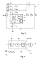
- the Fig. 1 shows an equivalent circuit diagram of a simplified model of a three-phase star point-compensated electrical distribution network 1 with three phase conductors 2, which consists of a line section 3 here.
- three phase conductors 2 which consists of a line section 3 here.
- several line sections 3 or line branches may be present or the distribution network 1 is not Sternretekompensiert.
- the distribution network 1 is shown here without consumers. Since, however, only the zero system is important in the invention, the exact topology of the electrical distribution network 1 has no significance.
- the supply transformer supplies the phase voltages U 1 , U 2 , U 3 and between the phases and earth form the phase ground voltages U 1E , U 2E , U 3E .
- the neutral earth admittance Y n Between star point 4 and earth is the neutral earth admittance Y n , or the neutral earth impedance X n , which, as is known, the reciprocal of the neutral earth admittance Y n , at which the zero voltage (neutral earth voltage) U ne is applied ,
- the sum of the zero currents of the individual line sections or line branches of the network flows back as zero current I o via the star point 4 to the feed transformer.
- the so-called zero voltage results from the sum of the individual phase ground voltages U 1E , U 2E , U 3E and is provided that the sum of the individual phase voltages U 1 , U 2 and U 3 of the network is zero, identical to the Neutral point ground voltage U ne .
- the so-called zero current I 0 corresponds to the current flowing in the ground and is calculated from the individual phase currents by summation.
- phase earth admittances of individual line sections 3 of the overall network 1 in the frequency range up to about 150 Hz can be described to a good approximation by the parallel connection of a section capacitance with a section leakage resistance.
- the three phase ground admittances Y 1 , Y 2 , Y 3 of the overall network 1 arise due to the non-consideration of the line length impedances by parallel connection of the phase earth admittances of the individual line sections 3 and thus by phase-related summation ofönsabitessadmittanzen on all line branches or sections 3 of the overall network. 1 ,
- an injection device 5 which has a first excellent terminal 6 and a second excellent terminal 7, as in FIGS Figs. 2 and 3 shown.
- the first terminal 6 is connected here, for example, to the second phase of the electrical network 1 and the second terminal 7 to ground.
- the injection device 5 is directly connected to the phase 2 with the phase ground voltage U 2E and the injection device 5 thus over the second phase with electrical energy supplied, an additional auxiliary supply in the form of an external power or voltage source can therefore be omitted.
- the phase ground voltages U 1E , U 2E , U 3E are usually available at the busbars or in the network 1 and can thus be easily tapped.
- an electrical dipole 8 represented by the admittance Y c or impedance X c is directly connected to the phase earth voltage U 2E and earth by means of a switching device 9 connected in series with this two-pole 8 between the second phase (selected here by way of example) ,
- the switching device 9 is switched, so depending on the version opened or closed.
- an injection current I inj the switching device 9 can also be omitted.
- This direct connection of the two-pole 8 of the injection device 5 requires that the switching device 9 can be exposed to very high voltage stresses. This can prevent the use of electronic circuit elements and the use of mechanical switching elements, such as e.g. make medium-voltage switches necessary, which ultimately increases the cost.
- a two-terminal 11 is connected via a single-phase transformer 10 to a freely selectable phase with the associated phase ground voltage U 1E , U 2E or U 3E .
- a transformer coupling or connection variant embodiment is accordingly Fig. 3 the high-voltage winding (primary side) 12 of a suitable single-phase transformer 10 or voltage converter via the first terminal 6 on the one hand to the phase ground voltage U 2E of the second phase (selected here by way of example) and connected via the terminal 7 on the other hand to ground.
- the injection device 5 is again supplied with electrical energy via a phase.
- a two-pole 11 represented by its admittance Y sec or impedance X sec is connected in series with a switching device 9.
- the switching device 9 may be carried out electronically or electromechanically due to the lower voltage level on the secondary side 13 of the single-phase transformer 10.
- this switching device 9 can now connect the two-pole 11 to the secondary side 13 of the transformer 10.
- an injection current l inj for a permanent injection of an auxiliary signal, for example, an injection current l inj , the switching device 9 can also be omitted.
- unipolar electronic switches e.g. Bipolar transistors, IGBTs, thyristors or FET's
- a suitable rectifier circuit or, for example, two unipolar electronic switches, each with a longitudinal diode connected in parallel with an array.
- Be bipolar electronic switching elements such. TRIAC's or electromechanical switches, so of course omitted the above-mentioned diodes.
- the impedances X sec and X c , and the admittances Y sec and Y c , the two poles 8, 11 can be formed by any circuit arrangement of electrical components, such as any serial or parallel combination of one or more ohmic resistors R, one or more Inductors L and / or one or more capacitors C, depending on the application. If, for example, a dirac-like injection current impulse is sought, then said two-pole 8, 11 is realized, for example, by a resistor R or by the series connection of a resistor R with a capacitor C. If an injection of predominantly power-frequency signals is desired, the use of a bipolar capacitor C or a choke coil with inductance L in relation to an ohmic resistance R for implementing the two-pole 8, 11 is advantageous for power loss reasons.
- the individual components of the dipole 8, 11 can also be automatically adjustable, for example via corresponding control commands of the higher-level control device 15, so that the impedances X sec and X c , or the admittances Y sec and Y c , and thus also the auxiliary signal to be injected , can also be adjusted as needed.
- the injection device 5 is not necessarily designed as a series connection of a two-pole 8, 11 with a switching device 9, but as an arbitrary Zweipol- or Mehrpolscensnetztechnik with two excellent electrical connections, the first excellent connection in the above analogous manner on the one hand with a the phase conductor of the network (with its associated phase ground voltage) and its second excellent terminal is connected to ground.
- the impedance or admittance of the two-pole or multi-pole circuit with respect to the two excellent connections (two-pole impedance) can additionally be changed continuously or in stages by means of a control device (ie also switched on or off).
- this control device is realized by an electrical or electronic switching device which allows the Laplace or Fourier transform of the impedance (admittance) of this two- or multi-pole circuit to assume two different states with respect to these two connections depending on the switch position.
- a control device which allows the impedance (admittance) of the two- or Mehrpolnetzwerkes with respect to the two excellent connections to change continuously, as is possible, for example, with clocked electronic control devices.
- the principle according to the invention for connecting injection devices 5 for injecting auxiliary signals into the zero system of the electrical distribution network 1, for example for generating zero voltage changes is not limited with regard to the number of injection devices 5 used.
- a plurality of injection devices 5 in any desired embodiment, for example with two-pole 8, 11 connected directly or transformer-connected, can be connected to the different phase ground voltages U 1E , U 2E , U 3E simultaneously or sequentially.
- the use of a plurality of injection devices 5, for example also at the same phase could, for example, be provided for the generation of special auxiliary signals, such as special pulse patterns.
- a higher-level control device 15 the timing and duration of the injection, and possibly also shape and power of the auxiliary signal to be injected, such as a pulse-shaped injection signal or a specific pulse pattern or an injection signal of certain voltage and phase, for example the control device 9 is driven accordingly.
- the injection device 5 may also have its own external control input 14, to which the control device 15 can be turned on.
- corresponding devices such as a microprocessor or a logic circuit for processing the control signals may be provided in the injection device 5.
- Such a synchronization device 25 could, for example, as in Fig. 4 shown, a band-pass filter 23, a PLL (phase locked loop) circuit 20 and a drive logic 21 have.
- a band-pass filtered measurement signal from the phase earth voltage U 1E , U 2E or U 3E used for injection is supplied to the PLL circuit 20, which passes on a phase-synchronized control signal to the drive logic 21.
- the switching device 9 can now be phase-synchronized via the drive logic 21, which is activated for example by an injection request 22, are controlled.
- this phase synchronization of the injection signal can naturally also be produced without any restriction of the principle with any other periodic power-frequency signal whose harmonic components may be filtered out with a band-pass filter tuned to the mains frequency.
- the synchronization device 25 can also be integrated in the injection device 5.
- the injection request 22 could for example also be supplied via an external control input 14 of the injection device 5 by the higher-level controller 15.
- an auxiliary signal is injected in the stationary state, for example by the two-pole 8, 11 is connected via the switching device 9 in the stationary initial state, and the injection, eg for the purpose of zero voltage change, by interrupting the injection, for example by switching off the two-pole 8, 11 by means of Switching device 9, is defined.
- This operating mode can be achieved by simple logical inversion of the control signal for the injection device 5 and can therefore be referred to as inverse operation.
Landscapes
- Cable Transmission Systems, Equalization Of Radio And Reduction Of Echo (AREA)
- Ac-Ac Conversion (AREA)
- Measurement Of Resistance Or Impedance (AREA)
Applications Claiming Priority (1)
| Application Number | Priority Date | Filing Date | Title |
|---|---|---|---|
| AT0016507A AT503929B1 (de) | 2007-02-01 | 2007-02-01 | Vorrichtung und ein verfahren zur injektion eines hilfssignals in das nullsystem eines elektrischen verteilnetzes |
Publications (2)
| Publication Number | Publication Date |
|---|---|
| EP1953890A2 true EP1953890A2 (fr) | 2008-08-06 |
| EP1953890A3 EP1953890A3 (fr) | 2015-03-18 |
Family
ID=39032444
Family Applications (1)
| Application Number | Title | Priority Date | Filing Date |
|---|---|---|---|
| EP20080150082 Withdrawn EP1953890A3 (fr) | 2007-02-01 | 2008-01-08 | Dispositif et procédé destinés à l'injection d'un signal auxiliaire dans le système homopolaire d'un réseau de distribution électrique |
Country Status (2)
| Country | Link |
|---|---|
| EP (1) | EP1953890A3 (fr) |
| AT (1) | AT503929B1 (fr) |
Cited By (3)
| Publication number | Priority date | Publication date | Assignee | Title |
|---|---|---|---|---|
| CN104034968A (zh) * | 2014-06-30 | 2014-09-10 | 阳光电源股份有限公司 | 一种光伏逆变器电网对地绝缘阻抗检测装置及方法 |
| WO2014194941A1 (fr) * | 2013-06-05 | 2014-12-11 | Siemens Aktiengesellschaft | Détection de défauts à la terre dans des réseaux de distribution d'énergie à point neutre compensé |
| CN106443358A (zh) * | 2016-11-08 | 2017-02-22 | 三峡大学 | 一种基于信号注入装置的架空配电网行波定位系统 |
Families Citing this family (1)
| Publication number | Priority date | Publication date | Assignee | Title |
|---|---|---|---|---|
| DE102015226783A1 (de) * | 2015-12-29 | 2017-06-29 | Bender Gmbh & Co. Kg | Verfahren und Vorrichtung zur Funktionsüberwachung einer Erdverbindung in einem Stromversorgungssystem |
Citations (4)
| Publication number | Priority date | Publication date | Assignee | Title |
|---|---|---|---|---|
| EP0595677A1 (fr) | 1992-10-26 | 1994-05-04 | Electricite De France | Procédé et dispositif de mesure de l'accord et du désaccord de compensation d'un réseau de distribution électrique |
| WO2002015355A2 (fr) | 2000-08-11 | 2002-02-21 | Adaptive Regelsysteme Gesellschaft M.B.H. | Procede et dispositif pour reconnaitre et localiser des defauts a la terre monopolaires a valeur ohmique elevee |
| WO2004003578A1 (fr) | 2002-06-26 | 2004-01-08 | Adaptive Regelsysteme Gesellschaft Mbh | Procede pour determiner un parametre d'un reseau electrique |
| EP1693679A1 (fr) | 2005-02-21 | 2006-08-23 | Adaptive Regelsysteme GmbH | Procédé pour la détermination d'un paramètre dans un réseau d'alimentation électrique |
Family Cites Families (4)
| Publication number | Priority date | Publication date | Assignee | Title |
|---|---|---|---|---|
| JP2576299B2 (ja) * | 1991-03-07 | 1997-01-29 | 株式会社日立製作所 | 配電線の微地絡検出装置 |
| AT404072B (de) * | 1995-02-28 | 1998-08-25 | Haefely Trench Austria Gmbh | Verfahren zur erkennung eines einpoligen erdschlusses in einem drehstromnetz |
| DE19525417C2 (de) * | 1995-07-12 | 2000-03-23 | Starkstrom Geraetebau Gmbh | Anordnung zur Erdschluß-Stromkompensation eines mehrphasigen elektrischen Leitungsnetzes |
| DE10307972B4 (de) * | 2003-02-24 | 2007-02-08 | Edc Gmbh | Verfahren zur Erkennung und Ortung von niederohmigen und hochohmigen Erdschlüssen in elektrischen Versorgungsnetzen |
-
2007
- 2007-02-01 AT AT0016507A patent/AT503929B1/de not_active IP Right Cessation
-
2008
- 2008-01-08 EP EP20080150082 patent/EP1953890A3/fr not_active Withdrawn
Patent Citations (4)
| Publication number | Priority date | Publication date | Assignee | Title |
|---|---|---|---|---|
| EP0595677A1 (fr) | 1992-10-26 | 1994-05-04 | Electricite De France | Procédé et dispositif de mesure de l'accord et du désaccord de compensation d'un réseau de distribution électrique |
| WO2002015355A2 (fr) | 2000-08-11 | 2002-02-21 | Adaptive Regelsysteme Gesellschaft M.B.H. | Procede et dispositif pour reconnaitre et localiser des defauts a la terre monopolaires a valeur ohmique elevee |
| WO2004003578A1 (fr) | 2002-06-26 | 2004-01-08 | Adaptive Regelsysteme Gesellschaft Mbh | Procede pour determiner un parametre d'un reseau electrique |
| EP1693679A1 (fr) | 2005-02-21 | 2006-08-23 | Adaptive Regelsysteme GmbH | Procédé pour la détermination d'un paramètre dans un réseau d'alimentation électrique |
Cited By (5)
| Publication number | Priority date | Publication date | Assignee | Title |
|---|---|---|---|---|
| WO2014194941A1 (fr) * | 2013-06-05 | 2014-12-11 | Siemens Aktiengesellschaft | Détection de défauts à la terre dans des réseaux de distribution d'énergie à point neutre compensé |
| CN104034968A (zh) * | 2014-06-30 | 2014-09-10 | 阳光电源股份有限公司 | 一种光伏逆变器电网对地绝缘阻抗检测装置及方法 |
| EP2963429A1 (fr) * | 2014-06-30 | 2016-01-06 | Sungrow Power Supply Co., Ltd. | Dispositif et procédé pour détecter l'impédance d'isolation d'une grille de puissance connectée avec un inverseur photovoltaïque par rapport à la terre |
| CN106443358A (zh) * | 2016-11-08 | 2017-02-22 | 三峡大学 | 一种基于信号注入装置的架空配电网行波定位系统 |
| CN106443358B (zh) * | 2016-11-08 | 2023-08-25 | 三峡大学 | 一种基于信号注入装置的架空配电网行波定位系统 |
Also Published As
| Publication number | Publication date |
|---|---|
| AT503929B1 (de) | 2008-02-15 |
| AT503929A4 (de) | 2008-02-15 |
| EP1953890A3 (fr) | 2015-03-18 |
Similar Documents
| Publication | Publication Date | Title |
|---|---|---|
| DE19930122C1 (de) | Verfahren zur Verhinderung des Draufschaltens auf in Abzweigen bestehende elektrische Kurzschlüsse und zugehörige Anordnung | |
| EP2332229B1 (fr) | Dispositif d'essai d'installation aérogénératrice | |
| EP1855366B1 (fr) | Circuit et procédé pour la compensation du courant de défaut pendant un défaut de terre | |
| DE19525417C2 (de) | Anordnung zur Erdschluß-Stromkompensation eines mehrphasigen elektrischen Leitungsnetzes | |
| EP3080821A1 (fr) | Dispositif et procédé visant à réduire une composante de flux magnétique continu dans le noyau d'un transformateur | |
| DE102008024348B4 (de) | Verfahren zur Reduktion pulsförmiger Erdströme an einem elektrischen Großgerät und Kompensationsschaltung zur Erdstromverlagerung | |
| AT503929B1 (de) | Vorrichtung und ein verfahren zur injektion eines hilfssignals in das nullsystem eines elektrischen verteilnetzes | |
| DE69329326T2 (de) | Verfahren und Vorrichtung zum Messen der Anpassung und Fehlanpassung der Kompensation eines Stromversorgungsnetzes | |
| EP3593434A1 (fr) | Procédé et agencement pour produire un signal de déclenchement pour un interrupteur ccht | |
| DE2502322C2 (de) | Erdschluß-Schutzeinrichtung | |
| EP3180844A1 (fr) | Ensemble convertisseur muni d'une unité de court-circuit ainsi que procédé de coupure d'une ligne à tension alternative | |
| WO2006082131A1 (fr) | Procede et dispositif pour determiner l'instant de commutation d'un appareil de commutation electrique | |
| EP3080822B1 (fr) | Dispositif et procédé visant à réduire une composante de flux magnétique continu dans le noyau d'un transformateur triphasé | |
| DE102011082554A1 (de) | Verfahren zur Bestimmung eines Erdschlussstroms in einem erdschlussbehafteten Drehstromnetz | |
| EP3646427B1 (fr) | Procédé et dispositif pour la connexion électrique d'un transformateur à un réseau électrique | |
| DE2845993A1 (de) | Fehlerstromschutzschaltungsanordnung | |
| DE2026685A1 (de) | Verfahren und Vorrichtung zum Abschalten von Gleichstrom-Energieübertragungsnetzen | |
| DE102008024420A1 (de) | Verfahren zur Bestimmung eines Schaltzeitpunktes eines elektrischen Schaltgerätes | |
| DE102014013417A1 (de) | Verfahren und Vorrichtung zur Bestimmung des Erdschlussfehlerstroms | |
| DE2604312A1 (de) | Schutzrelaiseinrichtung fuer kraftstrom-uebertragungsleitung | |
| EP1916530A1 (fr) | Dispositif et procédé destinés à la mesure de l'impédance de réseau au niveau de la moyenne tension | |
| DE658262C (de) | Fernmelde- und Fernsteuerungseinrichtung | |
| DE69711051T2 (de) | Verfahren und vorrichtung zur aufrechterhaltung der elektrischen stromversorgung in einem elektrischen mehrphasigen energieverteilungsnetz | |
| AT215520B (de) | Verfahren und Vorrichtung zum Schutz Stromnetzen gegen Kurzschlüsse | |
| EP2602895B1 (fr) | Circuit pour un appareil ménager et appareil ménager doté d'un tel circuit |
Legal Events
| Date | Code | Title | Description |
|---|---|---|---|
| PUAI | Public reference made under article 153(3) epc to a published international application that has entered the european phase |
Free format text: ORIGINAL CODE: 0009012 |
|
| AK | Designated contracting states |
Kind code of ref document: A2 Designated state(s): AT BE BG CH CY CZ DE DK EE ES FI FR GB GR HR HU IE IS IT LI LT LU LV MC MT NL NO PL PT RO SE SI SK TR |
|
| AX | Request for extension of the european patent |
Extension state: AL BA MK RS |
|
| RIC1 | Information provided on ipc code assigned before grant |
Ipc: H02H 9/08 20060101AFI20130620BHEP Ipc: G01R 31/02 20060101ALI20130620BHEP Ipc: H02H 3/00 20060101ALN20130620BHEP |
|
| PUAL | Search report despatched |
Free format text: ORIGINAL CODE: 0009013 |
|
| AK | Designated contracting states |
Kind code of ref document: A3 Designated state(s): AT BE BG CH CY CZ DE DK EE ES FI FR GB GR HR HU IE IS IT LI LT LU LV MC MT NL NO PL PT RO SE SI SK TR |
|
| AX | Request for extension of the european patent |
Extension state: AL BA MK RS |
|
| RIC1 | Information provided on ipc code assigned before grant |
Ipc: G01R 31/02 20060101ALI20150211BHEP Ipc: H02H 9/08 20060101AFI20150211BHEP Ipc: H02H 3/00 20060101ALN20150211BHEP |
|
| 17P | Request for examination filed |
Effective date: 20150917 |
|
| RBV | Designated contracting states (corrected) |
Designated state(s): AT BE BG CH CY CZ DE DK EE ES FI FR GB GR HR HU IE IS IT LI LT LU LV MC MT NL NO PL PT RO SE SI SK TR |
|
| RBV | Designated contracting states (corrected) |
Designated state(s): AT BE BG CH CY CZ DE DK EE ES FI FR GB GR HR HU IE IS IT LI LT LU LV MC MT NL NO PL PT RO SE SI SK TR |
|
| AKX | Designation fees paid |
Designated state(s): AT BE BG CH CY CZ DE DK EE ES FI FR GB GR HR HU IE IS IT LI LT LU LV MC MT NL NO PL PT RO SE SI SK TR |
|
| AXX | Extension fees paid |
Extension state: MK Extension state: RS Extension state: BA Extension state: AL |
|
| STAA | Information on the status of an ep patent application or granted ep patent |
Free format text: STATUS: REQUEST FOR EXAMINATION WAS MADE |
|
| STAA | Information on the status of an ep patent application or granted ep patent |
Free format text: STATUS: THE APPLICATION IS DEEMED TO BE WITHDRAWN |
|
| 18D | Application deemed to be withdrawn |
Effective date: 20170801 |