EP1954095A2 - Appareil de transmission et de réception sonore - Google Patents
Appareil de transmission et de réception sonore Download PDFInfo
- Publication number
- EP1954095A2 EP1954095A2 EP08101204A EP08101204A EP1954095A2 EP 1954095 A2 EP1954095 A2 EP 1954095A2 EP 08101204 A EP08101204 A EP 08101204A EP 08101204 A EP08101204 A EP 08101204A EP 1954095 A2 EP1954095 A2 EP 1954095A2
- Authority
- EP
- European Patent Office
- Prior art keywords
- sound
- waveguide
- directional microphone
- opening
- microphone
- Prior art date
- Legal status (The legal status is an assumption and is not a legal conclusion. Google has not performed a legal analysis and makes no representation as to the accuracy of the status listed.)
- Withdrawn
Links
Images





Classifications
-
- H—ELECTRICITY
- H04—ELECTRIC COMMUNICATION TECHNIQUE
- H04R—LOUDSPEAKERS, MICROPHONES, GRAMOPHONE PICK-UPS OR LIKE ACOUSTIC ELECTROMECHANICAL TRANSDUCERS; ELECTRIC HEARING AIDS; PUBLIC ADDRESS SYSTEMS
- H04R1/00—Details of transducers, loudspeakers or microphones
- H04R1/20—Arrangements for obtaining desired frequency or directional characteristics
- H04R1/32—Arrangements for obtaining desired frequency or directional characteristics for obtaining desired directional characteristic only
-
- H—ELECTRICITY
- H04—ELECTRIC COMMUNICATION TECHNIQUE
- H04R—LOUDSPEAKERS, MICROPHONES, GRAMOPHONE PICK-UPS OR LIKE ACOUSTIC ELECTROMECHANICAL TRANSDUCERS; ELECTRIC HEARING AIDS; PUBLIC ADDRESS SYSTEMS
- H04R25/00—Electric hearing aids
- H04R25/40—Arrangements for obtaining a desired directivity characteristic
- H04R25/402—Arrangements for obtaining a desired directivity characteristic using contructional means
-
- H—ELECTRICITY
- H04—ELECTRIC COMMUNICATION TECHNIQUE
- H04R—LOUDSPEAKERS, MICROPHONES, GRAMOPHONE PICK-UPS OR LIKE ACOUSTIC ELECTROMECHANICAL TRANSDUCERS; ELECTRIC HEARING AIDS; PUBLIC ADDRESS SYSTEMS
- H04R1/00—Details of transducers, loudspeakers or microphones
- H04R1/20—Arrangements for obtaining desired frequency or directional characteristics
- H04R1/32—Arrangements for obtaining desired frequency or directional characteristics for obtaining desired directional characteristic only
- H04R1/34—Arrangements for obtaining desired frequency or directional characteristics for obtaining desired directional characteristic only by using a single transducer with sound reflecting, diffracting, directing or guiding means
-
- H—ELECTRICITY
- H04—ELECTRIC COMMUNICATION TECHNIQUE
- H04R—LOUDSPEAKERS, MICROPHONES, GRAMOPHONE PICK-UPS OR LIKE ACOUSTIC ELECTROMECHANICAL TRANSDUCERS; ELECTRIC HEARING AIDS; PUBLIC ADDRESS SYSTEMS
- H04R3/00—Circuits for transducers
- H04R3/04—Circuits for transducers for correcting frequency response
-
- H—ELECTRICITY
- H04—ELECTRIC COMMUNICATION TECHNIQUE
- H04R—LOUDSPEAKERS, MICROPHONES, GRAMOPHONE PICK-UPS OR LIKE ACOUSTIC ELECTROMECHANICAL TRANSDUCERS; ELECTRIC HEARING AIDS; PUBLIC ADDRESS SYSTEMS
- H04R5/00—Stereophonic arrangements
-
- H—ELECTRICITY
- H04—ELECTRIC COMMUNICATION TECHNIQUE
- H04R—LOUDSPEAKERS, MICROPHONES, GRAMOPHONE PICK-UPS OR LIKE ACOUSTIC ELECTROMECHANICAL TRANSDUCERS; ELECTRIC HEARING AIDS; PUBLIC ADDRESS SYSTEMS
- H04R2225/00—Details of deaf aids covered by H04R25/00, not provided for in any of its subgroups
- H04R2225/023—Completely in the canal [CIC] hearing aids
-
- H—ELECTRICITY
- H04—ELECTRIC COMMUNICATION TECHNIQUE
- H04R—LOUDSPEAKERS, MICROPHONES, GRAMOPHONE PICK-UPS OR LIKE ACOUSTIC ELECTROMECHANICAL TRANSDUCERS; ELECTRIC HEARING AIDS; PUBLIC ADDRESS SYSTEMS
- H04R2225/00—Details of deaf aids covered by H04R25/00, not provided for in any of its subgroups
- H04R2225/43—Signal processing in hearing aids to enhance the speech intelligibility
Definitions
- the following description relates generally to an apparatus for transmitting and receiving sound.
- a microphone is a kind of sensors for detecting sound wave or vibration of ultrasonic wave and converting the sound wave or the vibration to an electric signal as an output.
- Microphones are used as a sound input apparatus in, for example, a recorder, a telephone, a loudspeaker and a hearing device.
- Omni-directional microphones have one sound entry opening and ideally accept sound from all directions equally to be susceptible to noise, and for that reason, directional microphones are frequently used to accentuate a useful acoustic signal in an environment filled with interference noise.
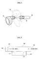
- FIGS. 1a and 1b illustrate a schematic constitutional view of a conventional omni-directional microphone and a sensitivity characteristic representation in response to sound input direction.
- the omni-directional microphone is held adjacent mouth of the user from which sound comes out in order to arrange the microphone nearest to the sound source when the microphone is used in a voice recorder or an ear-set for sound detection.
- an ear-hole (completely-in-the-canal) sound transmitter/receiver (10) has been developed that receives sound by detecting sound variations generated from a hole (21) of an ear (20) through vibration of ear drum during speaking instead of sound from a mouth.
- the ear-hole sound transmitter/receiver (10) has an advantage in that it is physically small in size, small enough to fit into a completely-in-the-canal (CIC) hearing aid and it can minimize environmental noise.
- An object of the present novel concept is to provide an apparatus for transmitting and receiving sound wherein a directional microphone for detecting sound for transmission is applied and a sound output unit for outputting the received sound is arranged at a side of the directional microphone where sensitivity is low to thereby attenuate the echo and howling.
- Another object is to provide an apparatus for transmitting and receiving sound wherein a directional microphone is applied to detect sound for transmission, thereby improving the SNR (Signal-to-Noise Ratio).
- Yet another object is to provide an apparatus for transmitting and receiving sound wherein interference noise in ear-holes caused by the received sound and utterance of a user can be attenuated even when the sound received from a sound output unit is being outputted to increase the detection efficiency of the sound in the ear-holes and to perform the full duplexing.
- an apparatus for transmitting and receiving sound is characterized by : a sound waveguide which is a pipe formed with one opening and the other opening, wherein at least two or more through holes are formed on the pipe by passing therethrough, a first sound is inputted into said one opening and a second sound is inputted into said other opening; a sound output unit disposed at said one opening of the sound waveguide to output the first sound to the sound waveguide; and a directional microphone for detecting the second sound by the through holes of the sound waveguide.
- an apparatus for transmitting and receiving sound may comprise: a sound waveguide (100) which is a pipe and formed with one opening (101) and the other opening (102), wherein at least two or more through holes (111, 112) are formed on the pipe by passing therethrough, a first sound is inputted into said one opening (101) and a second sound is inputted into said other opening (102); a sound output unit (120) formed at said one opening (101) of the sound waveguide (100) to output the first sound to the sound waveguide (100); and a directional microphone (200) for detecting the second sound by the through holes (111, 112) of the sound waveguide (100).
- the apparatus may work in such a manner that a first sound (received) is inputted into one opening (101) of the sound waveguide (100) and a second sound (to be transmitted) is inputted into the other opening (102).
- the sound waveguide (100) may be formed with at least two or more through holes (111, 112) through which the second sound is inputted into the directional microphone (200), where the directional microphone (200) may detect the second sound and transmits a second sound signal.
- the directional microphone preferably has one directional pattern out of such patterns as a cardoid pattern, a hypercardoid pattern and a secondary directional pattern.
- the cardoid pattern may be embodied by a directional microphone formed with two sound detection passages, and the secondary directional pattern may embody the directional pattern by arrangement of three or more microphones.
- the first sound is a sound wirely or wirelessly received from an outside device to the apparatus according to the present novel concept
- the second sound is a sound that is detected by the directional microphone (200) and transmitted wirely or wirelessly to the outside device.
- the directional microphone preferably includes a microphone detecting sound by using electromagnetism, a microphone detecting sound by using electrostatic capacity, and a microphone detecting sound by using piezoelectricity.
- the first sound is preferably a sound that advances from the sound output unit to the ear drum
- the second sound is preferably a sound that is generated from vibration of the ear drum by utterance of a user.
- the first sound is preferably a sound that is received wirely or wirelessly from an outside device
- the second sound is preferably a sound that is detected by the directional microphone and that is wirely or wirelessly transmitted to the outside device.
- the directional microphone (200) may comprise plural structures, and each of the plurality of directional microphones may comprise a directional microphone for detecting the second sound inputted into the through holes of the sound waveguide (100).
- FIG.4 is a schematic constitutional view illustrating the apparatus according to an exemplary implementation, wherein the sound output unit (120) disposed at one opening of the sound waveguide (100) may be a speaker (121) for outputting the first sound that is received, and the directional microphone (200) for receiving the second sound through the through holes (111, 112) of the sound waveguide (100) to output a sound signal may be a directional microphone (210) disposed with first and second detection passage (211, 212).
- the directional microphone (210) equipped with the first and second detection passage (211, 212) may receive most of the input from the second sound as sensitivity of the first sound outputted from the speaker (121) is low while that of the second sound is high.
- FIGS. 5a and 5b are a schematic constitutional view illustrating a directional microphone and a sensitivity characteristic representation in response to a sound input direction according to the present inventive concept.
- the directional microphone (210) mounted with the first and second detection passage (211, 212) works in such a fashion that detection sensitivity from the second detection passage (212) is high while that of the first detection passage (211) is low.
- the sensitivity is the highest at the front (0 0 ) and the lowest at the rear (180 0 ) in terms of sensitivity feature in response to sound input direction.
- the directional microphone formed at the apparatus of the instant novel feature is positioned toward a sound source to be transmitted to a direction where the sensitivity of the directional microphone is high, whereby the detected sound signal is higher than noise to help improve the SNR (Signal to Noise Ratio).
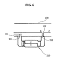
- FIG.6 is a schematic view illustrating a feature of a directional microphone according to the present inventive concept, where the sound detection passages (211 212) of the directional microphone (210) are connected to the through holes (111, 112) of the sound waveguide (100), and the first sound outputted from the sound output unit is inputted into the first and second detection passage (211, 212) of the directional microphone.
- the second sound (C) is inputted into the second detection passage (212).
- a first sound element (A) inputted into the first detection passage (211) and a first sound element (B) inputted into the second detection passage (212) create a phase difference in response to time delay.
- the first sound elements (A, B) respectively inputted into the first and second detection passage (211, 212) are offset by the phase difference to make the sensitivity low, whereas the sensitivity of the first sound at the directional microphone grows low while that of the second sound becomes high in response to the feature of the directional microphone where the sensitivity of a second sound element (C) inputted into the second detection passage (212).
- the sensitivity of the second detection passage (212) of the directional microphone (210) is the highest while that of the first detection passage (211) is the lowest, if the directional microphone is applied to the apparatus, there is a high likelihood of reducing interference noise between input/output sounds and blocking outside noise to further clearly detect the sound signal.
- FIG.7 is a schematic view illustrating a canal type ear-hole sound transmitter/receiver (500) formed with a built-in apparatus for transmitting and receiving sound.
- the canal type ear-hole sound transmitter/receiver (500) may be used by being inserted into an external auditory meatus (completely in the canal). As shown in FIG.7 , the canal type ear-hole sound transmitter/receiver (500) may be configured with an apparatus for transmitting and receiving sound (300) according to the present novel concept.
- the apparatus (300) may include a sound waveguide (100) formed with at least two or more through holes (111, 112) and formed with one opening into which a received first sound is inputted and the other opening into which a second sound to be transmitted is inputted, a speaker (121) formed at said one opening of the sound waveguide (100) to output the first sound, and a directional microphone (200) for receiving the second sound via the through holes (111, 112) of the sound waveguide (100) to output a sound signal.
- a sound waveguide (100) formed with at least two or more through holes (111, 112) and formed with one opening into which a received first sound is inputted and the other opening into which a second sound to be transmitted is inputted
- a speaker (121) formed at said one opening of the sound waveguide (100) to output the first sound
- a directional microphone (200) for receiving the second sound via the through holes (111, 112) of the sound waveguide (100) to output a sound signal.
- a port i.e., a port at 180° of FIG.7 ) where the detection sensitivity of the directional microphone (200) is low may be aligned adjacent the speaker (121), while a port (i.e., a port at 0° of FIG.7 ) where the sensitivity is the highest may be so aligned as to allow the second sound to be inputted.
- the first sound outputted from the speaker (121) may be transmitted to the ear drums of a user, where signal size thereof is low because the first sound is inputted from a direction where the sensitivity of the directional microphone (200) is low.
- the second sound which is a voice generated by vibration of the ear drums when a user speaks, is high in signal size thereof because the second sound is inputted from a direction where the sensitivity of the directional microphone (200) is the highest.
- the speaker (121) is connected to an antenna and a sound processor (not shown), sound wirelessly transmitted from a remote location is received by the antenna, processed by the sound processor and outputted to the speaker (121).
- the directional microphone (200) is also connected to the antenna and the sound processor (not shown), such that the second sound sensed by the directional microphone (200) is processed by the sound processor and transmitted to the antenna.
- the ear-hole (in-the-canal) sound transmitter/receiver is inserted into an ear hole of an ear (600) to transmit the received first sound into the ear drum, and to transmit the second sound generated from the ear drum of the ear (600) to a remote location through the sound waveguide and the directional microphone (200).
- the other opening of the sound waveguide (100) is preferably connected to an ear plug (510). At that, less interference may be generated between the first sound and the second sound to allow the sound output to be effectively transmitted to the user, thereby detecting the user's sound with the restrained distortion caused by the sound output.
- the ear plug (510) inserted into the ear hole including the external auditory meatus may serve to block the ear hole and to exclude outside sounds.
- the outside noise may not be detected therefore because the outside noise is inputted into a direction where the sensitivity of the directional microphone (200) is low.
- FIG.8 is a schematic view illustrating an apparatus for transmitting and receiving sound according to the present inventive concept.
- the sound waveguide (100) may be formed with a plurality of through holes (113a, 113b, 113c, 113d) and a plurality of microphones (221, 222, 223, 224) may be aligned correspondingly opposite to the plurality of through holes (113a, 113b, 113c, 113d).
- Each of the plurality of microphones (221, 222, 223, 224) may be a directional microphone having a secondary directional pattern.
- the second sound detected by the plurality of microphones (221, 222, 223, 224) may be compositely processed and outputted by a sound composite processor (250).
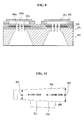
- FIG.9 is a schematic cross-sectional view illustrating a state where the plurality of microphones of FIG.8 is formed on a substrate.
- the plurality of microphones may be formed in such a manner that a first isolation layer (231) is formed on a substrate (230), a plurality of bottom electrodes (232) is formed on the first isolation layer (231), a second isolation layer (233) formed on the first isolation layer (231) and encompassing the plurality of bottom electrodes (232), each of the plurality of bottom electrodes is formed with etched substrate (230) regions, each of the etched substrate regions is formed with a plurality of through holes (235a, 235b, 235c) that penetrate from each etched substrate (230) regions to the second isolation layer (233), and a plurality of upper electrodes (234) discretely formed from the upper surface of the second isolation layer (233) formed on each of the plurality of the bottom electrodes (232).
- the plurality of upper electrodes (234) may surface from the upper surface of the second isolation layer (233), such that a space may exist between each of the upper electrodes (234) and the second isolation layer (233).
- Each of the etched substrate (230) regions is formed with a groove, and each of the grooves and each of the spaces may communicate with the plurality of through holes (235a, 235b, 235c).
- the sound transmitted to the grooves may be transmitted to the spaces through the plurality of through holes (235a, 235b, 235c). Pressure is changed in the spaces by the transmitted sound to change the electrostatic capacity between the plurality of upper electrodes (234) and the electrodes (232). As a result, the transmitted sound can be detected. Consequently, the plurality of microphones may be produced from a single substrate using MEMS (Micro-Electromechanical Systems) or micromachining, whereby characteristic variation of each microphone can be minimized and a manufacturing cost may be reduced by batch processing to realize the miniaturization.
- MEMS Micro-Electromechanical Systems
- FIG.10 is a schematic view illustrating an apparatus for transmitting and receiving sound according to still another exemplary implementation.
- the apparatus is applied with a sound waveguide (300) whose diameter increases from one opening (301) to the other opening (302).
- a first sound inputted into said one opening (301) having a diameter (dl) may be transmitted to the said other opening (302) to amplify the sound, such that the first sound can be heard much louder and clearly by the ear drum.
- FIG.11 is a schematic block diagram illustrating an apparatus for transmitting and receiving sound further comprising a transmitter and a receiver.
- the apparatus may include a receiver (510) for receiving a first sound from an external device, a sound waveguide (520) for outputting the first sound received from the receiver (510) to an ear drum (540) and receiving a second sound generated by vibration of the ear drum (540) by utterance of a user, a directional microphone (530) formed at the sound waveguide (520) to detect the second sound, and a transmitter (550) for transmitting the second sound detected by the directional microphone (530).
- a receiver (510) for receiving a first sound from an external device
- a sound waveguide (520) for outputting the first sound received from the receiver (510) to an ear drum (540) and receiving a second sound generated by vibration of the ear drum (540) by utterance of a user
- a directional microphone (530) formed at the sound waveguide (520) to detect the second sound
- a transmitter (550) for transmitting the second sound detected by the directional microphone (530).
- the receiver (510) of the apparatus may receive the first sound wirely or wirelessely from the external device, and the first sound received by the receiver (510) may be transmitted to the user's ear drum (540) via the sound waveguide (520).
- the second sound generated by the vibration of the ear drum (540) by the utterance of the user may be inputted to the sound waveguide (520), the directional microphone (530) disposed at the sound waveguide (520) may detect the second sound.
- the second sound detected by the directional microphone (530) may be transmitted to the external device by the transmitter (550). In doing so, the apparatus may reduce the interference noise between the received first sound and the second sound generated by utterance of the user for transmission to perform the full duplexing.
Landscapes
- Physics & Mathematics (AREA)
- Engineering & Computer Science (AREA)
- Acoustics & Sound (AREA)
- Signal Processing (AREA)
- Health & Medical Sciences (AREA)
- Otolaryngology (AREA)
- General Health & Medical Sciences (AREA)
- Neurosurgery (AREA)
- Circuit For Audible Band Transducer (AREA)
- Obtaining Desirable Characteristics In Audible-Bandwidth Transducers (AREA)
- Cable Transmission Systems, Equalization Of Radio And Reduction Of Echo (AREA)
Applications Claiming Priority (1)
| Application Number | Priority Date | Filing Date | Title |
|---|---|---|---|
| KR1020070011504A KR20080073022A (ko) | 2007-02-05 | 2007-02-05 | 음향 송수신 장치 |
Publications (2)
| Publication Number | Publication Date |
|---|---|
| EP1954095A2 true EP1954095A2 (fr) | 2008-08-06 |
| EP1954095A3 EP1954095A3 (fr) | 2008-08-20 |
Family
ID=39468868
Family Applications (1)
| Application Number | Title | Priority Date | Filing Date |
|---|---|---|---|
| EP08101204A Withdrawn EP1954095A3 (fr) | 2007-02-05 | 2008-02-01 | Appareil de transmission et de réception sonore |
Country Status (3)
| Country | Link |
|---|---|
| US (1) | US8462974B2 (fr) |
| EP (1) | EP1954095A3 (fr) |
| KR (1) | KR20080073022A (fr) |
Families Citing this family (8)
| Publication number | Priority date | Publication date | Assignee | Title |
|---|---|---|---|---|
| WO2008095167A2 (fr) | 2007-02-01 | 2008-08-07 | Personics Holdings Inc. | Procédé et dispositif d'enregistrement audio |
| US11317202B2 (en) | 2007-04-13 | 2022-04-26 | Staton Techiya, Llc | Method and device for voice operated control |
| US11217237B2 (en) | 2008-04-14 | 2022-01-04 | Staton Techiya, Llc | Method and device for voice operated control |
| US9129291B2 (en) | 2008-09-22 | 2015-09-08 | Personics Holdings, Llc | Personalized sound management and method |
| KR101213540B1 (ko) * | 2011-08-18 | 2012-12-18 | (주)에스엠인스트루먼트 | 멤스 마이크로폰 어레이를 이용한 음향감지 장치 및 음향카메라 |
| KR101213539B1 (ko) * | 2012-09-03 | 2012-12-18 | (주)에스엠인스트루먼트 | 멤스 마이크로폰 어레이를 이용한 음향감지 장치 및 음향카메라 |
| US10163453B2 (en) | 2014-10-24 | 2018-12-25 | Staton Techiya, Llc | Robust voice activity detector system for use with an earphone |
| SE539373C2 (en) * | 2015-10-19 | 2017-08-22 | Ascom Sweden Ab | Method and system for determining an available engine 11 |
Family Cites Families (8)
| Publication number | Priority date | Publication date | Assignee | Title |
|---|---|---|---|---|
| US3757769A (en) * | 1971-11-01 | 1973-09-11 | Grason Stadler Comp Inc | Acoustic admittance testing apparatus |
| US5882314A (en) * | 1991-12-17 | 1999-03-16 | Biomechanics, Inc. | Airway geometry imaging |
| US5524056A (en) * | 1993-04-13 | 1996-06-04 | Etymotic Research, Inc. | Hearing aid having plural microphones and a microphone switching system |
| US6705319B1 (en) * | 2000-05-26 | 2004-03-16 | Purdue Research Foundation | Miniature acoustical guidance and monitoring system for tube or catheter placement |
| WO2003047307A2 (fr) * | 2001-11-27 | 2003-06-05 | Corporation For National Research Initiatives | Microphone condenseur miniature et son procede de fabrication |
| TWI240589B (en) | 2004-04-23 | 2005-09-21 | Merry Electronics Co Ltd | Capacitor-type silicon-based micro-microphone and manufacture method thereof |
| US7769185B2 (en) * | 2005-05-19 | 2010-08-03 | Starkey Laboratories, Inc. | System for testing hearing assistance devices using a planar waveguide |
| KR100675023B1 (ko) * | 2005-09-14 | 2007-01-30 | 주식회사 비에스이 | 콘덴서 마이크로폰 및 이를 위한 패키징 방법 |
-
2007
- 2007-02-05 KR KR1020070011504A patent/KR20080073022A/ko not_active Abandoned
-
2008
- 2008-02-01 EP EP08101204A patent/EP1954095A3/fr not_active Withdrawn
- 2008-02-04 US US12/025,597 patent/US8462974B2/en active Active
Also Published As
| Publication number | Publication date |
|---|---|
| US8462974B2 (en) | 2013-06-11 |
| EP1954095A3 (fr) | 2008-08-20 |
| KR20080073022A (ko) | 2008-08-08 |
| US20080212815A1 (en) | 2008-09-04 |
Similar Documents
| Publication | Publication Date | Title |
|---|---|---|
| US8462974B2 (en) | Apparatus for transmitting and receiving sound | |
| CN101453684B (zh) | 声音输入装置 | |
| KR102472574B1 (ko) | 다수의 마이크로폰을 이용한 자동 노이즈 캔슬링 | |
| US9674604B2 (en) | Dual cartridge directional microphone | |
| EP2153435B1 (fr) | Appareil de communication avec réduction du bruit ambiant | |
| CN103460714B (zh) | 耳内传声器及耳内传声器用电压控制装置 | |
| JP2007516658A (ja) | 音響的に同調したポートを有するノイズ消去マイクロフォン | |
| WO2007115304A2 (fr) | Système transducteur pour moniteur et procédé de fabrication | |
| US20090214068A1 (en) | Transducer assembly | |
| US11019434B2 (en) | Hearing protection device with reliability and related methods | |
| US12317035B2 (en) | Hearing device for occlusion reduction and components thereof | |
| EP0852891B1 (fr) | Configuration de montage d'un microphone antibruit | |
| US9565501B2 (en) | Hearing device and method of identifying hearing situations having different signal sources | |
| US6266410B1 (en) | Speakerphone and microphone case for the same | |
| CN113259820B (zh) | 麦克风 | |
| JP7702396B2 (ja) | ヘッドセット | |
| CN113259819A (zh) | 麦克风 | |
| DK181516B1 (en) | Hearing device with a suspended microphone | |
| EP4440143A1 (fr) | Dispositif auditif | |
| CN121240016A (zh) | 一种集成式mems声学器件 | |
| CN120915880A (zh) | 带噪音抑制的对讲系统 | |
| KR20080058559A (ko) | 분리형 음향 입/출력 장치 |
Legal Events
| Date | Code | Title | Description |
|---|---|---|---|
| PUAI | Public reference made under article 153(3) epc to a published international application that has entered the european phase |
Free format text: ORIGINAL CODE: 0009012 |
|
| PUAL | Search report despatched |
Free format text: ORIGINAL CODE: 0009013 |
|
| 17P | Request for examination filed |
Effective date: 20080201 |
|
| AK | Designated contracting states |
Kind code of ref document: A2 Designated state(s): AT BE BG CH CY CZ DE DK EE ES FI FR GB GR HR HU IE IS IT LI LT LU LV MC MT NL NO PL PT RO SE SI SK TR |
|
| AX | Request for extension of the european patent |
Extension state: AL BA MK RS |
|
| AK | Designated contracting states |
Kind code of ref document: A3 Designated state(s): AT BE BG CH CY CZ DE DK EE ES FI FR GB GR HR HU IE IS IT LI LT LU LV MC MT NL NO PL PT RO SE SI SK TR |
|
| AX | Request for extension of the european patent |
Extension state: AL BA MK RS |
|
| 17Q | First examination report despatched |
Effective date: 20090226 |
|
| AKX | Designation fees paid |
Designated state(s): DE FR GB NL |
|
| STAA | Information on the status of an ep patent application or granted ep patent |
Free format text: STATUS: THE APPLICATION IS DEEMED TO BE WITHDRAWN |
|
| 18D | Application deemed to be withdrawn |
Effective date: 20090709 |