EP1954403B1 - Fluidproduktabgabepumpe - Google Patents
Fluidproduktabgabepumpe Download PDFInfo
- Publication number
- EP1954403B1 EP1954403B1 EP06820298A EP06820298A EP1954403B1 EP 1954403 B1 EP1954403 B1 EP 1954403B1 EP 06820298 A EP06820298 A EP 06820298A EP 06820298 A EP06820298 A EP 06820298A EP 1954403 B1 EP1954403 B1 EP 1954403B1
- Authority
- EP
- European Patent Office
- Prior art keywords
- pump
- piston
- fluid
- priming
- pump according
- Prior art date
- Legal status (The legal status is an assumption and is not a legal conclusion. Google has not performed a legal analysis and makes no representation as to the accuracy of the status listed.)
- Ceased
Links
Images

Classifications
-
- B—PERFORMING OPERATIONS; TRANSPORTING
- B05—SPRAYING OR ATOMISING IN GENERAL; APPLYING FLUENT MATERIALS TO SURFACES, IN GENERAL
- B05B—SPRAYING APPARATUS; ATOMISING APPARATUS; NOZZLES
- B05B11/00—Single-unit hand-held apparatus in which flow of contents is produced by the muscular force of the operator at the moment of use
- B05B11/01—Single-unit hand-held apparatus in which flow of contents is produced by the muscular force of the operator at the moment of use characterised by the means producing the flow
- B05B11/10—Pump arrangements for transferring the contents from the container to a pump chamber by a sucking effect and forcing the contents out through the dispensing nozzle
- B05B11/1001—Piston pumps
- B05B11/1004—Piston pumps comprising a movable cylinder and a stationary piston
-
- B—PERFORMING OPERATIONS; TRANSPORTING
- B05—SPRAYING OR ATOMISING IN GENERAL; APPLYING FLUENT MATERIALS TO SURFACES, IN GENERAL
- B05B—SPRAYING APPARATUS; ATOMISING APPARATUS; NOZZLES
- B05B11/00—Single-unit hand-held apparatus in which flow of contents is produced by the muscular force of the operator at the moment of use
- B05B11/01—Single-unit hand-held apparatus in which flow of contents is produced by the muscular force of the operator at the moment of use characterised by the means producing the flow
- B05B11/10—Pump arrangements for transferring the contents from the container to a pump chamber by a sucking effect and forcing the contents out through the dispensing nozzle
- B05B11/1001—Piston pumps
- B05B11/1016—Piston pumps the outlet valve having a valve seat located downstream a movable valve element controlled by a pressure actuated controlling element
-
- B—PERFORMING OPERATIONS; TRANSPORTING
- B05—SPRAYING OR ATOMISING IN GENERAL; APPLYING FLUENT MATERIALS TO SURFACES, IN GENERAL
- B05B—SPRAYING APPARATUS; ATOMISING APPARATUS; NOZZLES
- B05B11/00—Single-unit hand-held apparatus in which flow of contents is produced by the muscular force of the operator at the moment of use
- B05B11/01—Single-unit hand-held apparatus in which flow of contents is produced by the muscular force of the operator at the moment of use characterised by the means producing the flow
- B05B11/10—Pump arrangements for transferring the contents from the container to a pump chamber by a sucking effect and forcing the contents out through the dispensing nozzle
- B05B11/1042—Components or details
- B05B11/1061—Pump priming means
- B05B11/1063—Air exhausted from the pump chamber being discharged into the container during priming
-
- B—PERFORMING OPERATIONS; TRANSPORTING
- B05—SPRAYING OR ATOMISING IN GENERAL; APPLYING FLUENT MATERIALS TO SURFACES, IN GENERAL
- B05B—SPRAYING APPARATUS; ATOMISING APPARATUS; NOZZLES
- B05B11/00—Single-unit hand-held apparatus in which flow of contents is produced by the muscular force of the operator at the moment of use
- B05B11/01—Single-unit hand-held apparatus in which flow of contents is produced by the muscular force of the operator at the moment of use characterised by the means producing the flow
- B05B11/10—Pump arrangements for transferring the contents from the container to a pump chamber by a sucking effect and forcing the contents out through the dispensing nozzle
- B05B11/1042—Components or details
- B05B11/1073—Springs
- B05B11/1074—Springs located outside pump chambers
Definitions
- the present invention relates to a fluid dispenser pump and a fluid dispenser device comprising such a pump.
- Fluid dispensing pumps are well known in the state of the art, in particular for dispensing products in the fields of cosmetics, perfumery or pharmacy. They generally comprise a piston sliding in a pump body, more particularly in a pump chamber provided in this pump body, and adapted to dispense a dose of fluid product with each actuation of the pump.
- the pump chamber generally comprises an inlet valve to enable the dose of product expelled to be defined at each actuation.
- some pumps sometimes incorporate shutters at the dispensing orifice, to prevent contamination of the product between two actuations.
- EP-A-0251863 in accordance with the preamble of independent claim 1, discloses such a device.
- a problem with this type of pump is priming. Indeed, before the first actuation of the pump, the pump chamber is filled with air, and it is therefore necessary to expel this air completely to allow filling of said pump chamber with fluid and allow dosing accurate and reproducible with each actuation of the pump.
- the priming is made all the more complicated that the pump or the dispensing device comprises a shutter. It is difficult to expel the air contained in the pump chamber out of it, in particular because of the presence of said shutter.
- the presence of the shutter at the level of The dispensing orifice prevents the priming air from being expelled from the pump chamber through this dispensing orifice.
- the priming air must then be expelled into the tank, which in a conventional pump is achieved by using the dip tube whose main function is to bring fluid from the reservoir to the pump chamber.
- this priming is complicated or impossible, especially when this priming must be done by returning the priming air into the tank through the dip tube.
- the present invention aims to provide a fluid dispensing pump that does not reproduce the aforementioned drawbacks.
- Another object of the present invention is to provide a fluid dispenser pump which guarantees a spray spray each time the pump is actuated, regardless of the force that the user exerts on it when it is actuated.
- the present invention also aims to provide a fluid dispenser pump that is simple and inexpensive to manufacture and assemble.
- the present invention therefore relates to a fluid dispenser pump intended to be associated with a fluid reservoir, said pump comprising a pump body, a pump chamber, and at least a first piston sliding in said pump chamber for dispensing the fluid through a dispensing orifice, said pump having a priming air channel connecting said pump chamber to said reservoir during priming of the pump.
- said pump comprises a hollow dip tube defining inside a product channel connecting the pump chamber to the reservoir for supplying fluid to said pump chamber, said priming air channel being separated from said product channel.
- said priming air channel is formed outside said dip tube.
- said dip tube is inserted into a central channel of said first piston, said priming air channel being formed between said dip tube and said central channel of the first piston.
- said central channel of said first piston comprises a clamping part, in which said dip tube is fitted, and a part of larger diameter, defining with said dip tube said air channel.
- priming means at least one through-hole being formed through the wall of said central channel of said first piston, in said larger-diameter portion, for connecting said priming air channel to said pump chamber during the boot.
- said pump chamber comprises an inlet valve separating the pump chamber from the dip tube, said inlet valve comprising a valve seat integral with the first piston and a valve element.
- said first piston slides sealingly into said pump body, said pump body having an opening cooperating with the first piston during priming to open said priming air channel and allow the air to be forced back. contained in the pump chamber before the first actuation through the priming air channel in the tank.
- said first piston and said valve seat are made integrally with a fastening element, such as a snap ring, crimpable or screwable, adapted to fix said pump on the fluid reservoir.
- a fastening element such as a snap ring, crimpable or screwable
- said pump comprises a shutter displaceable and / or deformable a closed position of the dispensing orifice and an open position of the dispensing orifice.
- the pump body is made of a one-piece piece with said shutter.
- said shutter is biased elastically, in particular by a spring, towards its closed position and is moved and / or deformed towards its open position by the pressure of the product contained in the pump chamber.
- said pump comprises a dispensing head incorporating said dispensing orifice, said shutter comprising at least one sliding piston, preferably axially, in said head.
- a single spring urges said first piston towards its rest position and said shutter towards its closed position.
- said spring is out of contact with the fluid product.
- the present invention also relates to a fluid dispenser device comprising a fluid reservoir and a pump as described above.
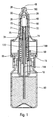
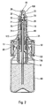
- the dispensing pump comprises a pump body 10 in which at least a first piston 72 slides.
- This first piston 72 partially defines a pump chamber 20 and the actuation of the pump causes the dispensing a dose of product contained in the pump chamber 20 through a dispensing orifice 45, preferably formed in a dispensing head 40.
- the pump advantageously comprises a shutter 38, arranged directly upstream of the dispensing orifice 45, and cooperating with it by being displaceable and / or deformable between a closed position of the dispensing orifice 45 and an open position thereof.
- the present invention therefore applies in particular to PFS devices provided with such a shutter.
- the pump chamber may comprise an inlet valve 70, which may be in the form of a ball 75 forming a valve element and cooperating with a valve seat 71.
- the pump body 10 is preferably formed of a one-piece piece with the shutter 38, inside thereof, the first piston 72 sliding inside this pump body 10.
- the piston 72 and the valve seat 71 are integral with a monobloc piece, which can also incorporate a fixing ring 15 adapted to fix the pump on a reservoir 60 containing the fluid, preferably with the interposition of a seal 65.
- a dip tube 18, intended to extend to at the bottom of the tank 60 to distribute all the product it contains, can also be made integrally with said fixing ring member 15, piston 72 and valve seat 71.
- the valve member 75 is represented in the form of a ball, but it could be realized differently.
- the pump comprises a priming air channel 100 adapted to connect the pump chamber 20 to the reservoir, preferably only during priming of the pump.
- the channel 100 is preferably separated from the dip tube 18, so that the priming air is no longer supplied to the bottom of the tank by the dip tube, which avoids the creation of "broths" or air bubbles in the product, which can be re-extracted later.
- the priming is improved and the dose regularity is better.
- an expulsion of the priming air through the dip tube can be difficult, if not impossible, the air does not have enough energy to reach the mouth of the dip tube, at the bottom of the tank.
- the present invention which physically separates the paths taken by the priming air and the product, overcomes these disadvantages, particularly in PFS devices.
- the separation of the liquid and air paths also makes it possible to optimize the size of the dip tube as a function of the fluid product to be used.
- the air channel 100 is formed outside the plunger tube 18, especially around it.
- the hollow interior of the dip tube 18 thus forms a product channel 118, and the air channel is formed around this product channel.
- the plunger tube 18 is inserted, in particular force-fitted, into a hollow central channel 172 of the first piston 72.
- the air channel 100 is then formed between the outside of the plunger tube 18 and the inside of said central channel 172.
- said central channel 172 comprises a clamping part, in which the plunger tube 18 is force-fitted, for example at its upper part with reference to the figures, and a part of larger diameter, defining with said dip tube 18 said air channel 100.
- At least one through hole 74 is formed through the wall of said larger diameter portion of the central channel 172, to connect said air channel 100 to said pump chamber 20 when priming the pump.
- each passage opening 74 can be made in the form of a lateral bore made in the valve seat 71 upstream of the valve member. 75.
- the valve seat 71 is then advantageously disposed upstream of the first piston 72, which slides in a sealed manner in said pump body.
- This starting position is represented in particular on the figure 2 . It is found that when the user actuates the pump for the first time and that it contains air in the pump chamber 20, the air is compressed, which closes the inlet valve 70 by pressing the ball 75 against the valve seat 71. The air being compressible, the first piston 72 can slide in the pump body 10 without the shutter 38 moves relative to the dispensing head 40.
- the pump has only one spring 50 adapted to return the first piston 72 to its rest position and the shutter 38 to its closed position after each actuation.
- This spring 50 is advantageously out of contact with the fluid, which eliminates any risk of alteration of the fluid in question.
- the shutter 38 slides axially between its open and closed positions in a sleeve 150 provided in the bottom of the actuating head 40.
- a spraying profile (not shown) is preferably made in said sleeve to enable a swirling of the product at the time of its expulsion, to form a spray.
- the shutter 38 may comprise second and third pistons 34, 35, preferably made integrally with said shutter 38. Said second and third pistons 34 and 35 can slide in a sealed manner in the head 40, between a closed position and an open position, for example in parts of the head 40 which may have different diameters.
- the plunger tube 18 is not necessarily integral or made in one piece with the fixing element 15 which fixes the pump on the reservoir 60.
- the shapes of the shutter 38, of the air channel priming 100, plunger tube 18, pump body 10, piston 72, inlet valve 70, pump chamber 20 or other elements could be made differently if necessary.
- the way in which these elements cooperate, and in particular the way in which they are fixed to each other, could be modified.
- Other modifications are also conceivable for those skilled in the art without departing from the scope of the present invention as defined by the appended claims.
Landscapes
- Reciprocating Pumps (AREA)
- Containers And Packaging Bodies Having A Special Means To Remove Contents (AREA)
- Details Of Reciprocating Pumps (AREA)
- Medical Preparation Storing Or Oral Administration Devices (AREA)
Claims (15)
- Abgabepumpe für ein fluidförmiges Produkt, die dazu bestimmt ist, mit einem Behälter (60) für das fluidförmige Produkt verbunden zu werden, wobei die Pumpe einen Pumpenkörper (10), eine Pumpenkammer (20) und wenigstens einen ersten Kolben (72) umfasst, der in der Pumpenkammer (20) gleitet, um das fluidförmige Produkt durch eine Abgabeöffnung (45) hindurch abzugeben, wobei die Pumpe einen Produktkanal (118) aufweist, der die Pumpenkammer (20) mit dem Behälter (60) verbindet, um der Pumpenkammer (20) fluidförmiges Produkt zuzuführen sowie einen Inbetriebnahme-Luftkanal (100), der die Pumpenkammer (20) mit dem Behälter (60) während des in Betriebnehmens der Pumpe verbindet, dadurch gekennzeichnet, dass der Inbetriebnahme-Luftkanal (100) vom Produktkanal (118) getrennt ist.
- Pumpe nach Anspruch 1, bei welcher die Pumpe ein hohles Verlängerungsrohr (18) umfasst, die das Innere des Produktkanals (118) umschließt.
- Pumpe nach Anspruch 2, bei welcher der Inbetriebnahme-Luftkanal (100) außerhalb des Verlängerungsrohres (18) ausgebildet ist.
- Pumpe nach Anspruch 2 oder 3, bei welcher das Verlängerungsrohr (18) in einen Zentralkanal (172) des ersten Kolbens (72) eingeführt ist, wobei der Inbetriebnahme-Luftkanal (100) zwischen dem Verlängerungsrohr (18) und dem Zentralkanal (172) des ersten Kolbens (72) ausgebildet ist.
- Pumpe nach Anspruch 4, bei welcher der Zentralkanal (172) des ersten Kolbens (72) einen Klemmbereich aufweist, in den das Verlängerungsrohr (18) eingepresst ist, sowie einen Teil mit größerem Durchmesser, der zusammen mit dem Verlängerungsrohr (18) den Inbetriebnahme-Luftkanal (100) definiert, wenigstens eine Durchgangsöffnung (74) welche durch die Wand des Zentralkanals (172) des ersten Kolbens (72) hindurch in den besagten Bereich mit größerem Durchmesser hinein ausgebildet ist, um den Inbetriebnahme-Luftkanal (100) mit der Pumpenkammer (20) bei der Inbetriebnahme zu verbinden.
- Pumpe nach einem der vorhergehenden Ansprüche, bei welcher die Pumpenkammer (20) ein Eintrittsventil (70) umfasst, das die Pumpenkammer (20) von dem Verlängerungsrohr (18) trennt, wobei das Eintrittsventil (70) einen Ventilsitz (71), der mit dem ersten Kolben (72) fest verbunden ist, sowie ein Ventilelement (75) aufweist.
- Pumpe nach Anspruch 6, bei welcher der erste Kolben (72) und der Ventilsitz (71) einstückig mit einem Befestigungselement (15) wie z.B. einem einrastbaren, einpressbaren oder einschraubbaren Ring ausgebildet ist, der geeignet ist, die Pumpe auf dem Behälter (60) für das fluidförmige Produkt zu befestigen.
- Pumpe nach einem der vorhergehenden Ansprüche, bei welcher der erste Kolben (72) in dichter Weise in dem Pumpenkörper (10) gleitet, wobei der Pumpenkörper (10) eine Öffnung (32) aufweist, die während der Inbetriebnahme mit dem ersten Kolben (72) zusammenarbeitet, um den Inbetriebnahme-Luftkanal (100) zu öffnen und die Verdrängung der in der Pumpenkammer (20) enthaltenen Luft vor der ersten Betätigung durch den Inbetriebnahme-Luftkanal (100) in dem Behälter (60) zu ermöglichen.
- Pumpe nach einem der vorhergehenden Ansprüche, bei welcher die Pumpe einen Verschluss (38) umfasst, der zwischen einer Verschlussstellung für die Abgabeöffnung (45) und einer Öffnungsstellung für die Abgabeöffnung (45) verschiebbar und/oder verformbar ist.
- Pumpe nach Anspruch 9 bei welcher der Pumpenkörper (10) einstückig mit dem Verschluss (38) ausgebildet ist.
- Pumpe nach Anspruch 9 oder 10 bei welcher der Verschluss (38) in elastischer Weise, insbesondere durch eine Feder (50) in seine Verschlussstellung vorgespannt ist und in seine Öffnungsstellung durch den Druck des in der Pumpenkammer (20) enthaltenen Produktes verschoben und /oder verformt wird.
- Pumpe nach einem der Ansprüche 9 bis 11, bei welcher die Pumpe einen Abgabekopf (40) aufweist, in welchem die Abgabeöffnung (45) vorgesehen ist, wobei der Verschluss (38) wenigstens einen Kolben (34, 35) aufweist, der, vorzugsweise axial, in dem Kopf (40) gleitet.
- Pumpe nach einem der Ansprüche 9 bis 12, bei welcher eine einzige Feder (50) den ersten Kolben (72) in seine Ruhestellung und den Verschluss (38) in seine Verschlussstellung vorspannt.
- Pumpe nach Anspruch 13, bei welcher die Feder (50) in keinerlei Kontakt mit dem fluidförmigen Produkt kommt.
- Abgabevorrichtung für ein fluidförmiges Produkt, die einen Behälter (60) für das fluidförmige Produkt umfasst, dadurch gekennzeichnet, dass sie eine Pumpe nach einem der vorhergehenden Ansprüche aufweist.
Applications Claiming Priority (2)
| Application Number | Priority Date | Filing Date | Title |
|---|---|---|---|
| FR0553139A FR2892158B1 (fr) | 2005-10-17 | 2005-10-17 | Pompe de distribution de produit fluide |
| PCT/FR2006/051037 WO2007045791A2 (fr) | 2005-10-17 | 2006-10-17 | Pompe de distribution de produit fluide |
Publications (2)
| Publication Number | Publication Date |
|---|---|
| EP1954403A2 EP1954403A2 (de) | 2008-08-13 |
| EP1954403B1 true EP1954403B1 (de) | 2012-02-15 |
Family
ID=36500328
Family Applications (1)
| Application Number | Title | Priority Date | Filing Date |
|---|---|---|---|
| EP06820298A Ceased EP1954403B1 (de) | 2005-10-17 | 2006-10-17 | Fluidproduktabgabepumpe |
Country Status (6)
| Country | Link |
|---|---|
| US (1) | US8292131B2 (de) |
| EP (1) | EP1954403B1 (de) |
| JP (1) | JP4918096B2 (de) |
| CN (1) | CN101316660B (de) |
| FR (1) | FR2892158B1 (de) |
| WO (1) | WO2007045791A2 (de) |
Cited By (2)
| Publication number | Priority date | Publication date | Assignee | Title |
|---|---|---|---|---|
| EP3821927A1 (de) | 2019-11-14 | 2021-05-19 | GSK Consumer Healthcare S.A. | Vorrichtung zur inneren und äusseren nasalen anwendung |
| WO2021094451A1 (en) | 2019-11-14 | 2021-05-20 | GSK Consumer Healthcare S.A. | Device for internal and external nasal application |
Families Citing this family (13)
| Publication number | Priority date | Publication date | Assignee | Title |
|---|---|---|---|---|
| US20130269684A1 (en) | 2012-04-16 | 2013-10-17 | Dance Pharmaceuticals, Inc. | Methods and systems for supplying aerosolization devices with liquid medicaments |
| US8950394B2 (en) | 2010-01-12 | 2015-02-10 | Dance Biopharm Inc. | Preservative-free single dose inhaler systems |
| DE102011106261A1 (de) * | 2011-05-18 | 2012-11-22 | Meadwestvaco Calmar Gmbh | Spender zur dosierten Abgabe von flüssigen Medien |
| CN102502101B (zh) * | 2011-10-12 | 2013-08-21 | 深圳市博纳药品包装材料有限公司 | 一种流体分配泵 |
| CN102847627B (zh) * | 2012-10-15 | 2015-04-15 | 深圳市博纳药品包装材料有限公司 | 一种流体制剂分配喷雾泵 |
| CN104058180B (zh) * | 2013-03-18 | 2017-03-01 | F·霍尔泽有限责任公司 | 药剂分配器 |
| JP5803045B2 (ja) * | 2013-03-18 | 2015-11-04 | ヤン、ギョンオック | 薬剤ディスペンサ |
| US20140355610A1 (en) * | 2013-05-31 | 2014-12-04 | Qualcomm Incorporated | Switched power line communication |
| KR101760627B1 (ko) * | 2016-12-06 | 2017-07-24 | 주식회사 삼화플라스틱 | 립글로스 용기 |
| WO2019182745A1 (en) | 2018-03-19 | 2019-09-26 | Bryn Pharma, LLC | Epinephrine spray formulations |
| CN109592203B (zh) * | 2018-11-19 | 2020-02-14 | 深圳博纳精密给药系统股份有限公司 | 一种无菌喷雾泵 |
| PL3738677T3 (pl) * | 2019-05-16 | 2022-03-28 | Brill Engines, S.L. | Urządzenie odpowiednie do dozowania substancji ciekłych |
| EP4703045A1 (de) * | 2024-09-03 | 2026-03-04 | Aptar Radolfzell GmbH | Austragkopf und fluidspender mit einem solchen austragkopf |
Family Cites Families (14)
| Publication number | Priority date | Publication date | Assignee | Title |
|---|---|---|---|---|
| US3388839A (en) | 1966-12-12 | 1968-06-18 | Donald V. Frydenberg | Metering dispenser with piston confined in a rotatable element |
| EP0251863B1 (de) * | 1986-06-17 | 1993-04-21 | VALOIS Société Anonyme dite: | Dosiereinheit für ein pappiges oder dickflüssiges Produkt |
| FR2656900B1 (fr) * | 1990-01-10 | 1994-01-28 | Oreal | Pompe manuelle a precompression pour la pulverisation d'un liquide, notamment d'un parfum. |
| DE4400944A1 (de) * | 1994-01-14 | 1995-07-20 | Ursatec Verpackung Gmbh | Saug-Druckpumpe für Fluidbehälter |
| JP3042357B2 (ja) * | 1995-03-15 | 2000-05-15 | 東洋製罐株式会社 | トリガ式ポンプディスペンサ |
| US6050457A (en) * | 1995-12-06 | 2000-04-18 | The Procter & Gamble Company | High pressure manually-actuated spray pump |
| DE19622124A1 (de) * | 1996-06-01 | 1997-12-04 | Alfred Von Schuckmann | Gerät zum Aufbringen von Flüssigkeiten |
| FR2831876B1 (fr) * | 2001-11-07 | 2004-04-23 | Valois Sa | Pompe de distribution de produit fluide |
| US7147135B2 (en) * | 2002-07-25 | 2006-12-12 | Valois Sas | Manually actuated fluid dispenser pump |
| FR2862107B1 (fr) * | 2003-11-07 | 2006-02-10 | Valois Sas | Pompe de distribution de produit fluide. |
| FR2862106B1 (fr) * | 2003-11-07 | 2007-08-24 | Valois Sas | Pompe de distribution de produit fluide. |
| FR2862009B1 (fr) * | 2003-11-07 | 2007-01-05 | Valois Sas | Tete de pulverisation de produit fluide et pompe de distribution comportant une telle tete. |
| FR2898818B1 (fr) * | 2006-03-22 | 2008-08-22 | Valois Sas | Pompe de distribution de produit fluide |
| FR2917651B1 (fr) * | 2007-06-20 | 2010-09-17 | Rexam Dispensing Sys | Pompe pour la distribution d'un produit liquide a amorcage ameliore |
-
2005
- 2005-10-17 FR FR0553139A patent/FR2892158B1/fr not_active Expired - Fee Related
-
2006
- 2006-10-17 JP JP2008536095A patent/JP4918096B2/ja not_active Expired - Fee Related
- 2006-10-17 CN CN2006800440541A patent/CN101316660B/zh active Active
- 2006-10-17 US US12/089,807 patent/US8292131B2/en active Active
- 2006-10-17 EP EP06820298A patent/EP1954403B1/de not_active Ceased
- 2006-10-17 WO PCT/FR2006/051037 patent/WO2007045791A2/fr not_active Ceased
Cited By (2)
| Publication number | Priority date | Publication date | Assignee | Title |
|---|---|---|---|---|
| EP3821927A1 (de) | 2019-11-14 | 2021-05-19 | GSK Consumer Healthcare S.A. | Vorrichtung zur inneren und äusseren nasalen anwendung |
| WO2021094451A1 (en) | 2019-11-14 | 2021-05-20 | GSK Consumer Healthcare S.A. | Device for internal and external nasal application |
Also Published As
| Publication number | Publication date |
|---|---|
| JP2009511827A (ja) | 2009-03-19 |
| CN101316660B (zh) | 2010-09-29 |
| FR2892158A1 (fr) | 2007-04-20 |
| WO2007045791A2 (fr) | 2007-04-26 |
| US8292131B2 (en) | 2012-10-23 |
| US20090140010A1 (en) | 2009-06-04 |
| JP4918096B2 (ja) | 2012-04-18 |
| WO2007045791A3 (fr) | 2007-06-07 |
| EP1954403A2 (de) | 2008-08-13 |
| CN101316660A (zh) | 2008-12-03 |
| FR2892158B1 (fr) | 2011-10-21 |
Similar Documents
| Publication | Publication Date | Title |
|---|---|---|
| EP0954485B1 (de) | Vorrichtung zur abgabe vom fliessfähigen produkt mit verschlussvorrichtung | |
| EP2004333B1 (de) | Fluidproduktabgabepumpe | |
| EP1697670B1 (de) | Fluidproduktsprühkopf und diesen sprühkopf umfassende abgabepumpe | |
| EP1954403A2 (de) | Fluidproduktabgabepumpe | |
| EP1687097B1 (de) | Pumpe zur abgabe eines fluidprodukts | |
| WO2010004224A2 (fr) | Pompe de distribution de produit fluide | |
| EP2069072B1 (de) | Spenderanordnung und spender für ein flüssigprodukt mit derartiger spenderanordnung | |
| EP1687095B1 (de) | Pumpe zur abgabe von fluidprodukten | |
| WO2003041865A1 (fr) | Tete de distribution et distributeur de produit fluide comportant une telle tete de distribution | |
| EP3400106A1 (de) | Nasale abgabeanordnung für ein flüssiges produkt und verfahren zur betätigung der anordnung | |
| EP4472778B1 (de) | Vorrichtung zur abgabe eines flüssigen produkts und verfahren zum füllen davon | |
| WO2010004212A1 (fr) | Dispositif de distribution de produit fluide | |
| EP1497039B1 (de) | Abgabepumpe für medien | |
| WO2022263771A1 (fr) | Tete de pulverisation pour dispositif de distribution de produit fluide | |
| EP4448065B1 (de) | Vorrichtung zur abgabe eines flüssigen produkts und verfahren zum füllen davon | |
| WO2026099115A1 (fr) | Dispositif de distribution de produit fluide | |
| WO2026013075A1 (fr) | Dispositif de distribution de produit fluide | |
| BE854005A (fr) | Distributeur a pompe d'atomisation |
Legal Events
| Date | Code | Title | Description |
|---|---|---|---|
| PUAI | Public reference made under article 153(3) epc to a published international application that has entered the european phase |
Free format text: ORIGINAL CODE: 0009012 |
|
| 17P | Request for examination filed |
Effective date: 20080617 |
|
| AK | Designated contracting states |
Kind code of ref document: A2 Designated state(s): DE FR GB IT |
|
| DAX | Request for extension of the european patent (deleted) | ||
| RBV | Designated contracting states (corrected) |
Designated state(s): DE FR GB IT |
|
| R17P | Request for examination filed (corrected) |
Effective date: 20080516 |
|
| GRAP | Despatch of communication of intention to grant a patent |
Free format text: ORIGINAL CODE: EPIDOSNIGR1 |
|
| GRAS | Grant fee paid |
Free format text: ORIGINAL CODE: EPIDOSNIGR3 |
|
| GRAA | (expected) grant |
Free format text: ORIGINAL CODE: 0009210 |
|
| AK | Designated contracting states |
Kind code of ref document: B1 Designated state(s): DE FR GB IT |
|
| REG | Reference to a national code |
Ref country code: GB Ref legal event code: FG4D Free format text: NOT ENGLISH |
|
| REG | Reference to a national code |
Ref country code: DE Ref legal event code: R096 Ref document number: 602006027672 Country of ref document: DE Effective date: 20120412 |
|
| PLBE | No opposition filed within time limit |
Free format text: ORIGINAL CODE: 0009261 |
|
| STAA | Information on the status of an ep patent application or granted ep patent |
Free format text: STATUS: NO OPPOSITION FILED WITHIN TIME LIMIT |
|
| 26N | No opposition filed |
Effective date: 20121116 |
|
| REG | Reference to a national code |
Ref country code: DE Ref legal event code: R097 Ref document number: 602006027672 Country of ref document: DE Effective date: 20121116 |
|
| REG | Reference to a national code |
Ref country code: DE Ref legal event code: R082 Ref document number: 602006027672 Country of ref document: DE Representative=s name: BITTNER & PARTNER, DE |
|
| REG | Reference to a national code |
Ref country code: DE Ref legal event code: R082 Ref document number: 602006027672 Country of ref document: DE Representative=s name: BITTNER & PARTNER, DE |
|
| REG | Reference to a national code |
Ref country code: DE Ref legal event code: R082 Ref document number: 602006027672 Country of ref document: DE Representative=s name: BITTNER & PARTNER, DE Effective date: 20130729 Ref country code: DE Ref legal event code: R082 Ref document number: 602006027672 Country of ref document: DE Representative=s name: BITTNER & PARTNER, DE Effective date: 20130731 Ref country code: DE Ref legal event code: R081 Ref document number: 602006027672 Country of ref document: DE Owner name: APTAR FRANCE SAS, FR Free format text: FORMER OWNER: VALOIS SAS, LE NEUBOURG, FR Effective date: 20130729 Ref country code: DE Ref legal event code: R082 Ref document number: 602006027672 Country of ref document: DE Representative=s name: BITTNER & PARTNER RECHTS- UND PATENTANWAELTE, DE Effective date: 20130731 Ref country code: DE Ref legal event code: R082 Ref document number: 602006027672 Country of ref document: DE Representative=s name: BITTNER & PARTNER RECHTS- UND PATENTANWAELTE, DE Effective date: 20130729 Ref country code: DE Ref legal event code: R082 Ref document number: 602006027672 Country of ref document: DE Representative=s name: STAUDT IP LAW, DE Effective date: 20130729 Ref country code: DE Ref legal event code: R082 Ref document number: 602006027672 Country of ref document: DE Representative=s name: STAUDT IP LAW, DE Effective date: 20130731 |
|
| REG | Reference to a national code |
Ref country code: DE Ref legal event code: R082 Ref document number: 602006027672 Country of ref document: DE Representative=s name: STAUDT IP LAW, DE |
|
| REG | Reference to a national code |
Ref country code: FR Ref legal event code: PLFP Year of fee payment: 10 |
|
| REG | Reference to a national code |
Ref country code: FR Ref legal event code: PLFP Year of fee payment: 11 |
|
| REG | Reference to a national code |
Ref country code: FR Ref legal event code: PLFP Year of fee payment: 12 |
|
| REG | Reference to a national code |
Ref country code: FR Ref legal event code: PLFP Year of fee payment: 13 |
|
| P01 | Opt-out of the competence of the unified patent court (upc) registered |
Effective date: 20230526 |
|
| PGFP | Annual fee paid to national office [announced via postgrant information from national office to epo] |
Ref country code: GB Payment date: 20231019 Year of fee payment: 18 |
|
| REG | Reference to a national code |
Ref country code: DE Ref legal event code: R082 Ref document number: 602006027672 Country of ref document: DE Representative=s name: SONNENBERG HARRISON PARTNERSCHAFT MBB PATENT- , DE |
|
| PGFP | Annual fee paid to national office [announced via postgrant information from national office to epo] |
Ref country code: IT Payment date: 20231009 Year of fee payment: 18 Ref country code: FR Payment date: 20231027 Year of fee payment: 18 Ref country code: DE Payment date: 20231011 Year of fee payment: 18 |
|
| REG | Reference to a national code |
Ref country code: DE Ref legal event code: R119 Ref document number: 602006027672 Country of ref document: DE |
|
| GBPC | Gb: european patent ceased through non-payment of renewal fee |
Effective date: 20241017 |
|
| PG25 | Lapsed in a contracting state [announced via postgrant information from national office to epo] |
Ref country code: DE Free format text: LAPSE BECAUSE OF NON-PAYMENT OF DUE FEES Effective date: 20250501 |
|
| PG25 | Lapsed in a contracting state [announced via postgrant information from national office to epo] |
Ref country code: GB Free format text: LAPSE BECAUSE OF NON-PAYMENT OF DUE FEES Effective date: 20241017 |
|
| PG25 | Lapsed in a contracting state [announced via postgrant information from national office to epo] |
Ref country code: FR Free format text: LAPSE BECAUSE OF NON-PAYMENT OF DUE FEES Effective date: 20241031 |
|
| PG25 | Lapsed in a contracting state [announced via postgrant information from national office to epo] |
Ref country code: IT Free format text: LAPSE BECAUSE OF NON-PAYMENT OF DUE FEES Effective date: 20241017 |