EP1955729B1 - Ligne d'électrodes et élément de raccord pour un stimulateur cardiaque implantable - Google Patents
Ligne d'électrodes et élément de raccord pour un stimulateur cardiaque implantable Download PDFInfo
- Publication number
- EP1955729B1 EP1955729B1 EP07023315.0A EP07023315A EP1955729B1 EP 1955729 B1 EP1955729 B1 EP 1955729B1 EP 07023315 A EP07023315 A EP 07023315A EP 1955729 B1 EP1955729 B1 EP 1955729B1
- Authority
- EP
- European Patent Office
- Prior art keywords
- terminal piece
- intermediate pieces
- proximal
- longitudinal
- piece according
- Prior art date
- Legal status (The legal status is an assumption and is not a legal conclusion. Google has not performed a legal analysis and makes no representation as to the accuracy of the status listed.)
- Not-in-force
Links
- 230000000747 cardiac effect Effects 0.000 claims description 8
- 230000007704 transition Effects 0.000 claims description 6
- 238000009413 insulation Methods 0.000 claims description 4
- 239000000463 material Substances 0.000 claims description 3
- 238000001746 injection moulding Methods 0.000 claims description 2
- 239000004413 injection moulding compound Substances 0.000 claims 8
- 239000004696 Poly ether ether ketone Substances 0.000 claims 2
- JUPQTSLXMOCDHR-UHFFFAOYSA-N benzene-1,4-diol;bis(4-fluorophenyl)methanone Chemical compound OC1=CC=C(O)C=C1.C1=CC(F)=CC=C1C(=O)C1=CC=C(F)C=C1 JUPQTSLXMOCDHR-UHFFFAOYSA-N 0.000 claims 2
- 229920002530 polyetherether ketone Polymers 0.000 claims 2
- 229910000679 solder Inorganic materials 0.000 claims 2
- 230000003247 decreasing effect Effects 0.000 claims 1
- 229920002635 polyurethane Polymers 0.000 claims 1
- 239000004814 polyurethane Substances 0.000 claims 1
- 229920001169 thermoplastic Polymers 0.000 claims 1
- 239000004416 thermosoftening plastic Substances 0.000 claims 1
- 125000006850 spacer group Chemical group 0.000 description 5
- 238000002788 crimping Methods 0.000 description 4
- 238000003466 welding Methods 0.000 description 3
- 229920001296 polysiloxane Polymers 0.000 description 2
- 238000005476 soldering Methods 0.000 description 2
- 230000000638 stimulation Effects 0.000 description 2
- 208000015943 Coeliac disease Diseases 0.000 description 1
- 241000238367 Mya arenaria Species 0.000 description 1
- 230000008901 benefit Effects 0.000 description 1
- 230000008859 change Effects 0.000 description 1
- 230000001419 dependent effect Effects 0.000 description 1
- 238000005538 encapsulation Methods 0.000 description 1
- 230000007717 exclusion Effects 0.000 description 1
- 238000002347 injection Methods 0.000 description 1
- 239000007924 injection Substances 0.000 description 1
- 238000002955 isolation Methods 0.000 description 1
- 238000004519 manufacturing process Methods 0.000 description 1
- 239000003550 marker Substances 0.000 description 1
- 238000000034 method Methods 0.000 description 1
- 230000008569 process Effects 0.000 description 1
- 230000035939 shock Effects 0.000 description 1
Images


Classifications
-
- A—HUMAN NECESSITIES
- A61—MEDICAL OR VETERINARY SCIENCE; HYGIENE
- A61N—ELECTROTHERAPY; MAGNETOTHERAPY; RADIATION THERAPY; ULTRASOUND THERAPY
- A61N1/00—Electrotherapy; Circuits therefor
- A61N1/02—Details
- A61N1/04—Electrodes
- A61N1/05—Electrodes for implantation or insertion into the body, e.g. heart electrode
- A61N1/056—Transvascular endocardial electrode systems
-
- H—ELECTRICITY
- H01—ELECTRIC ELEMENTS
- H01R—ELECTRICALLY-CONDUCTIVE CONNECTIONS; STRUCTURAL ASSOCIATIONS OF A PLURALITY OF MUTUALLY-INSULATED ELECTRICAL CONNECTING ELEMENTS; COUPLING DEVICES; CURRENT COLLECTORS
- H01R13/00—Details of coupling devices of the kinds covered by groups H01R12/70 or H01R24/00 - H01R33/00
- H01R13/46—Bases; Cases
- H01R13/514—Bases; Cases composed as a modular blocks or assembly, i.e. composed of co-operating parts provided with contact members or holding contact members between them
-
- H—ELECTRICITY
- H01—ELECTRIC ELEMENTS
- H01R—ELECTRICALLY-CONDUCTIVE CONNECTIONS; STRUCTURAL ASSOCIATIONS OF A PLURALITY OF MUTUALLY-INSULATED ELECTRICAL CONNECTING ELEMENTS; COUPLING DEVICES; CURRENT COLLECTORS
- H01R13/00—Details of coupling devices of the kinds covered by groups H01R12/70 or H01R24/00 - H01R33/00
- H01R13/46—Bases; Cases
- H01R13/52—Dustproof, splashproof, drip-proof, waterproof, or flameproof cases
- H01R13/5224—Dustproof, splashproof, drip-proof, waterproof, or flameproof cases for medical use
-
- H—ELECTRICITY
- H01—ELECTRIC ELEMENTS
- H01R—ELECTRICALLY-CONDUCTIVE CONNECTIONS; STRUCTURAL ASSOCIATIONS OF A PLURALITY OF MUTUALLY-INSULATED ELECTRICAL CONNECTING ELEMENTS; COUPLING DEVICES; CURRENT COLLECTORS
- H01R24/00—Two-part coupling devices, or either of their cooperating parts, characterised by their overall structure
- H01R24/58—Contacts spaced along longitudinal axis of engagement
-
- H—ELECTRICITY
- H01—ELECTRIC ELEMENTS
- H01R—ELECTRICALLY-CONDUCTIVE CONNECTIONS; STRUCTURAL ASSOCIATIONS OF A PLURALITY OF MUTUALLY-INSULATED ELECTRICAL CONNECTING ELEMENTS; COUPLING DEVICES; CURRENT COLLECTORS
- H01R2107/00—Four or more poles
-
- H—ELECTRICITY
- H01—ELECTRIC ELEMENTS
- H01R—ELECTRICALLY-CONDUCTIVE CONNECTIONS; STRUCTURAL ASSOCIATIONS OF A PLURALITY OF MUTUALLY-INSULATED ELECTRICAL CONNECTING ELEMENTS; COUPLING DEVICES; CURRENT COLLECTORS
- H01R2201/00—Connectors or connections adapted for particular applications
- H01R2201/12—Connectors or connections adapted for particular applications for medicine and surgery
Definitions
- the invention relates to an electrode lead for connection to an implantable cardiac stimulator such as a pacemaker or a cardioverter / defibrillator.
- an implantable cardiac stimulator such as a pacemaker or a cardioverter / defibrillator.
- the invention relates to a connector for such an electrode line.
- Implantable cardiac stimulators of the type mentioned are basically known in various designs. Such cardiac stimulators usually have a sealed housing which includes a power supply and other electronic and electrical components to generate stimulation pulses or defibrillation shocks and deliver via an electrode lead to one or more chambers of a heart or to detect and process electronic potentials in the heart.
- implantable cardiac stimulators are usually connected to electrode leads, which are inserted with a connector at the proximal end of the electrode lead into a socket in a so-called header of the respective cardiac stimulator. Both the connector and the socket in the header of the cardiac stimulator have electrical contacts corresponding to each other to establish an electrically conductive connection between the cardiac stimulator and the electrode lead.
- the connector at the proximal end of the electrode lead has electrical contacts connected to leads which provide at least the portion of an electrical connection to stimulation and / or sense electrodes in the region of the distal end of such an electrode lead.
- Such electrode lines are usually flexible (ie bend soft) and known in manifold design.
- the present invention applies to the fitting at the proximal end of the electrode lead and its connection to other electrode leads.
- the connector concerned here is of the type that has a plurality of annular contacts of the same outside diameter and corresponds to the future standard IS-4.
- a variant of such a connector is, for example, in US 2005/0221671 described.
- the object of the invention is to provide a connection piece and an electrode line with such a connection piece, which are independent of the type and number of contacts of the electrode line, are to produce with reasonable effort and have a high reliability.
- this object is achieved by a connector and by an electrode line with a connector having a plurality of annular, electrically conductive contacts same outer diameter with longitudinally disposed therebetween insulation portions of the same outer diameter, of which the electrically conductive contacts each electrically connected to an electrically conductive connection line are.
- the connecting piece according to the invention is formed by a plurality of insulating intermediate pieces and held by these electrical contacts with connecting leads attached thereto, plugged together in the longitudinal direction of the connecting piece and encapsulated after being plugged together with insulating plastic.
- the connection lines either do not protrude at all or at most extend beyond the distal end of the connection piece, which is smaller than the remaining length of the connection piece
- the intermediate pieces are preferably produced as pre-molded parts by means of injection molding.
- the connector according to the invention is designed so that it is to be connected as a separate unit with a remaining electrode line.
- overmolding required sprues and absolutely necessary parting lines of injection molds are placed so that an outer surface of the insulating plastic in the region between the individual electrical contacts and proximal of the most proximal contact arranged have no tool marks.
- overmolding can also be done in several steps with different materials, resulting in a heterogeneous external structure that at least partially encloses the intermediate pieces.
- the intermediate pieces may be formed and plugged together in the longitudinal direction that they form together with the electrical contacts, the outer contour of the connector and an enclosed by the intermediate pieces interior of the connector with insulating plastic is injected.
- the intermediate pieces serve both the axial and radial position assurance of the electrically conductive contacts.
- connection piece In order to ensure a rational production and to increase the reliability of the connection piece, it is provided that at least two of the insulating intermediate pieces are identical to one another. This has the further advantage that the connecting piece can be readily constructed with one, two or three annular contacts, without the need for other components.
- the identical intermediate pieces each have a snug fit for a respective annular contact.
- the respective intermediate piece at least in a longitudinal section, has an outer dimension which corresponds to the inner diameter of the annular contacts.
- the identical intermediate pieces in a respective proximal longitudinal section have a longitudinal stop which limits a sliding of a respective annular contact in the proximal direction.
- the longitudinal section preferably has a longitudinal distance to a proximal end of a respective intermediate piece, the Longitudinal distance between the annular contacts corresponds and thus defines the insulation length between the annular contacts.
- the identical intermediate pieces In a distal longitudinal section, the identical intermediate pieces have a smaller outer diameter than in their proximal longitudinal section.
- the outer diameter of the distal longitudinal section is dimensioned such that a respective distal longitudinal section fits exactly into a central opening in the proximal longitudinal section of an identical intermediate piece, so that the intermediate sections are to be inserted into one another in this way.
- a section of the respective proximal longitudinal section of a respective intermediate piece with its relatively larger outer diameter forms the seat for a respective annular contact.
- the intermediate pieces have on their outer side at least one recess extending in the longitudinal direction, which serves to receive a respective connecting line of an annular contact.
- the connecting piece preferably has a distal end piece, which has a proximal end portion and a distal end portion. Both end portions preferably have approximately the same outer diameter.
- the proximal end portion of the distal end piece preferably corresponds to a respective proximal longitudinal portion of the intermediate pieces between the proximal end of the respective intermediate piece and the longitudinal stop, i. H. the proximal end portions of all intermediate pieces and the distal end piece are equal.
- the distal end piece has in its proximal end portion preferably at least one longitudinally extending recess for receiving a connecting lead of an annular contact.
- the distal end piece is not formed for receiving a further annular contact, but rather to be connected to the other electrode line.
- the mated intermediate pieces and the end piece are preferably aligned with each other such that the respective recesses on the outside of the intermediate pieces and the end piece are aligned with each other and allow a respective lead to be stretched and guided parallel to the longitudinal axis of the fitting in the recesses.
- a respective lead to be stretched and guided parallel to the longitudinal axis of the fitting in the recesses.
- each intermediate piece and in the distal end piece two or three of the recesses are provided uniformly distributed over the circumference.
- the recesses in the proximal longitudinal sections of larger diameter of the intermediate pieces are offset relative to the recesses in the distal longitudinal sections in the circumferential direction.
- a central lumen that extends centrally through all of the identical spacers as well as through the end cap and can centrally receive a proximal end of, for example, a helical electrical lead.
- a segment is provided at the proximal end of the connecting piece, which is inserted in the opening at the proximal end of that of the identical intermediate pieces, which is located at the proximal end of the connecting piece.
- Different electrode line configurations with a fixed or rotatable electrode cable can be attached to the finished connection piece via the segment without having to change the connection piece.
- the connector of the type described above is preferably part of an electrode line having in its distal end at least one electrode and moreover at least one electrical lead, with its distal end electrically connected to this electrode and with its proximal end with a connected load an annular contact of the connection piece is electrically conductively connected via a crimping, welding or soldering connection.
- the crimping, welding or soldering connection is preferably located in each case in one of the longitudinally extending recesses of the distal end piece of the connection piece. Since the distal end piece itself is made of insulating plastic and the individual electrical leads and connecting lines are electrically insulated from each other by the various recesses in the end piece, no further isolation of the connection point is required even after connecting the respective connecting line with the associated electrical supply line.
- the electrode lead preferably includes a helically coiled (helical) lead extending between the distal and proximal ends of the electrode lead and extending with a proximal lead end portion in the lumen of the fitting.
- connection piece or of the electrode line mentioned in the dependent claims can be combined with one another.
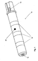
- fitting 10 has three annular contacts 12, which on one of in FIG. 1 not further recognizable spacers 14 formed carrier are arranged.
- the annular contacts 12 are each provided with leads 16 proximate a distal end of the fitting 10 (in FIG. 1 the right end of the fitting 10) ends.
- a key surface 18 At the proximal end of the fitting 10 is a key surface 18, which is part of a key segment 20 (see FIG. 2 ).
- the connecting piece 10 is encapsulated with insulating plastic, the insulating surfaces 22 between bare, electrically conductive outer surfaces of the annular contacts 12 forms.
- FIG. 2 the components of the connector 10 are shown individually in an exploded view.
- three annular contacts 12 are provided with connection lines 16 attached to them. Since the annular contacts 12, like FIG. 1 can be seen, are offset in the longitudinal direction of the connecting piece 10 to each other, the connecting lines 16 of the individual annular contacts 12 have different lengths and thus have at their respective distal end the same distance from the distal end of the connector 10th
- Each of the annular contact elements 12 is supported by a respective intermediate piece 14.
- three intermediate pieces 14 are provided, which are identical to each other.
- Each of the intermediate pieces 14 has a proximal longitudinal portion 24 and a distal longitudinal portion 26 and a transitional region 28 therebetween.
- a portion of the proximal longitudinal portion 24 of a respective intermediate piece 14 serves as a seat 30 for a respective annular contact 12.
- the respective distal longitudinal sections 26 of a respective intermediate piece 14 have a smaller diameter than the proximal longitudinal sections 24, which is dimensioned such that a respective distal longitudinal section 26 can be snugly inserted into a central opening in the proximal longitudinal section 24 of an identical intermediate section 14.
- several intermediate pieces 14 can be connected to each other in the longitudinal direction. In the transition region 26 between the two longitudinal sections of a respective intermediate piece 14, the outer diameter of the intermediate piece is reduced.
- recesses 34, 36 and 38 On the outside of the longitudinal sections 24 and 26 of the intermediate pieces 14 are provided in the longitudinal direction extending recesses 34, 36 and 38. These recesses 34, 36 and 38 serve to receive a respective connection line 16 of an annular contact 12.
- the recesses 34, 36 and 38 are arranged so that a connection line 16 of a respective contact 12 from the outside of a respective proximal longitudinal portion of the corresponding intermediate piece 14th in a recess (in this case in each case the recess 38) is guided to the outside of the distal longitudinal portion 26 of the respective intermediate piece 14.
- the remaining recesses 36 are arranged on a respective distal longitudinal section 26 of an intermediate piece 14 in extension of an opening 40 in the transitional area 28 of a respective intermediate piece 14.
- the apertures 40 allow a respective recess 38 to continue in a straight direction in correspondingly aligned recesses 36 of one or more intermediate pieces 14 arranged more distally.
- a termination piece 42 having a proximal end portion 44 and a distal end portion 46.
- the proximal end portion 44 is configured similar to the proximal longitudinal portions 24 of the intermediate pieces 14, but has no seat for a further annular electrode.
- the distal end portion 46 of the end piece 42 has approximately the same outer diameter as the proximal end portion 44 of the end piece 42 and also has longitudinal recesses 48. As FIG. 1 it can be seen, terminate the connecting lines 16 in a respective one of these wells 48 when the connector 10 is fully assembled. The ends of the connecting lines 16 are accessible in the recesses 48 from the outside.
- FIG. 3 shows a plugged spacer 10 before encapsulation with insulating plastic.
- FIG. 4 In order to connect the finished connector 10 with a remaining electrode line, more parts are required in FIG. 4 are shown. These are a silicone sleeve 50, a closing ring 52, a plug pin 54 and a marking tape 56.
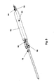
- the end piece 10 can be connected to a proximal end of an as far as preconfigured electrode line 60, as shown in FIG FIG. 5 is shown.
- FIG. 5 shows only the proximal end of such preconfigured electrode lead 60.
- the electrode line 60 has a flexurally soft shell 62, which has a central lumen for a central, helically coiled feed line 64 and further outwardly arranged lumens for electrical leads 66.
- the electrical supply lines 66 are equipped at their respective proximal end with a respective crimping sleeve 68, which serves to connect the electrical supply lines 66 to the connection lines 16 of the annular electrodes 12.
- a sleeve 70 which extends through a continuous central lumen of the fitting 10 enclosed by the endpiece 42 and the spacers 14 when the fitting 10 is secured to the electrode lead 60.
- a proximal end of the sleeve 70 is then connected to the male pin 54.
- the plug pin 54 then forms a central contact for the helically coiled line 64th
- the crimp sleeves 68 are attached by crimping at the ends of the leads 66.
- the sleeve 70 is connected by laser welding to the proximal end of the helically coiled line 64.
- the prepared, in FIG. 5 The illustrated proximal end of the electrode lead 60 is then inserted into the fitting 10 and fixed to the plug pin 54.
- the silicone sleeve 50 and the end ring 52 are then brought over the transition points as connecting elements.
- the marker band 56 covers a Abschmelzkante for the laser weld between the connector pin 54 and the sleeve 70 from.
Landscapes
- Health & Medical Sciences (AREA)
- Heart & Thoracic Surgery (AREA)
- Vascular Medicine (AREA)
- Cardiology (AREA)
- Engineering & Computer Science (AREA)
- Biomedical Technology (AREA)
- Nuclear Medicine, Radiotherapy & Molecular Imaging (AREA)
- Radiology & Medical Imaging (AREA)
- Life Sciences & Earth Sciences (AREA)
- Animal Behavior & Ethology (AREA)
- General Health & Medical Sciences (AREA)
- Public Health (AREA)
- Veterinary Medicine (AREA)
- Electrotherapy Devices (AREA)
Claims (22)
- Pièce de raccordement pour une ligne d'électrode, pour le raccordement d'un stimulateur cardiaque implantable et/ou d'un défibrillateur implantable, la pièce de raccordement comportant plusieurs contacts annulaires électriquement conducteurs (12) présentant un diamètre extérieur identique, avec des sections isolantes du même diamètre agencées entre ceux-ci dans le sens longitudinal, les contacts électriquement conducteurs étant respectivement reliés de façon électriquement conductrice à une ligne de raccordement électriquement conductrice, et la pièce de raccordement étant constituée de plusieurs pièces intermédiaires isolantes (14), certaines des pièces intermédiaires isolantes étant identiques les unes aux autres, et de contacts électriques maintenus par celles-ci, auxquels sont fixées des lignes de raccordement, lesquels sont emboîtés puis reliés suite à l'emboîtement, au moyen d'une matière thermoplastique à mouler par injection, la pièce de raccordement étant au surplus conçue pour être reliée en tant qu'unité autonome à une autre ligne d'électrode, caractérisée en ce que les pièces intermédiaires identiques entre elles présentent un diamètre extérieur plus petit dans une section longitudinale respectivement distale que dans leur section longitudinale proximale, le diamètre extérieur étant mesuré dans la section longitudinale distale de manière à ce qu'une section longitudinale distale respective soit exactement adaptée à une ouverture centrale dans la section longitudinale proximale d'une pièce intermédiaire identique, de sorte que les pièces intermédiaires s'emboîtent ainsi les unes dans les autres et sont ainsi reliées entre elles.
- Pièce de raccordement selon la revendication 1, caractérisée en ce que les pièces intermédiaires isolantes sont agencées à l'intérieur de la pièce de raccordement et en ce que le contour extérieur de la pièce de raccordement est formé par la matière à mouler par injection, ensemble avec les contacts électriquement conducteurs, par enrobage par injection des pièces intermédiaires avec la matière à mouler par injection, après l'assemblage des pièces intermédiaires et des contacts électriques.
- Pièce de raccordement selon la revendication 1, caractérisée en ce que les pièces intermédiaires isolantes forment le contour extérieur de la pièce de raccordement, ensemble avec les contacts électriquement conducteurs, et renferment un espace intérieur dans lequel est introduite la matière à mouler par injection, après l'assemblage des pièces intermédiaires et des contacts électriques, par moulage par injection.
- Pièce de raccordement selon l'une des revendications 1 à 3, caractérisée en ce que les lignes de raccordement se terminent à proximité de l'extrémité distale de la pièce de raccordement.
- Pièce de raccordement selon l'une des revendications 1 à 4, caractérisée en ce que la matière à mouler par injection est constituée d'une seule matière.
- Pièce de raccordement selon la revendication 5, caractérisée en ce que la matière à mouler par injection est constituée de PEEK.
- Pièce de raccordement selon l'une des revendications 1 à 4, caractérisée en ce que la matière à mouler par injection contient au moins deux matières.
- Pièce de raccordement selon la revendication 7, caractérisée en ce que la matière à mouler par injection contient du PEEK et du polyuréthane.
- Pièce de raccordement selon l'une des revendications 1 à 8, caractérisée en ce que les pièces intermédiaires identiques entre elles présentent respectivement une assise précise pour un contact annulaire respectif.
- Pièce de raccordement selon la revendication 9, caractérisée en ce que dans une section longitudinale proximale respective, les pièces intermédiaires identiques entre elles possèdent une butée longitudinale délimitant un emboîtement du contact annulaire dans la direction proximale.
- Pièce de raccordement selon la revendication 10, caractérisée en ce que la butée longitudinale présente un espacement longitudinal par rapport à l'extrémité proximale de chacune des pièces intermédiaires identiques, cet espacement longitudinal définissant l'espacement longitudinal et donc également la longueur d'isolation entre les contacts annulaires.
- Pièce de raccordement selon l'une des revendications 1 à 11, caractérisée en ce que la section longitudinale proximale de chacune des pièces intermédiaires forme l'assise pour un contact annulaire respectif, avec son diamètre extérieur relativement plus grand.
- Pièce de raccordement selon l'une des revendications 1 à 12, caractérisée en ce que sur leur côté extérieur, les pièces intermédiaires identiques entre elles comportent respectivement au moins un creux s'étendant dans le sens longitudinal, pour l'admission d'une ligne de raccordement d'un contact annulaire.
- Pièce de raccordement selon la revendication 13, caractérisée en ce que les pièces intermédiaires identiques entre elles comportent une région de transition entre leur section longitudinale proximale respective et leur section longitudinale distale respective, dans laquelle le diamètre extérieur diminue et lequel comporte une percée dans le prolongement d'un creux respectif, laquelle mène de l'extérieur de la section longitudinale distale vers l'intérieur de la section longitudinale proximale.
- Pièce de raccordement selon l'une des revendications 1 à 14, caractérisée en ce que la pièce de raccordement comporte une pièce terminale distale possédant une section d'extrémité proximale et une section d'extrémité distale, présentant toutes deux quasiment le même diamètre extérieur et parmi lesquelles la section d'extrémité proximale de la pièce terminale distale correspond à une section longitudinale proximale respective des pièces intermédiaires identiques situées entre l'extrémité proximale de la pièce intermédiaire respective et la butée longitudinale de ladite pièce intermédiaire.
- Pièce de raccordement selon la revendication 15, caractérisée en ce que dans son côté extérieur, la section d'extrémité proximale de la pièce terminale distale comporte au moins un creux s'étendant dans le sens longitudinal, pour l'admission d'une ligne de raccordement d'un contact annulaire.
- Pièce de raccordement selon les revendications 13 et 16, caractérisée en ce que sur le pourtour de leurs sections longitudinales ou de la section d'extrémité distale, chacune des pièces intermédiaires et la pièce terminale distale comportent respectivement trois creux répartis régulièrement sur le pourtour respectif, pour l'admission d'un total de trois lignes de raccordement de contacts annulaires également au nombre de trois, lesquels sont orientés les uns par rapport aux autres de manière à être respectivement en affleurement dans le sens longitudinal.
- Pièce de raccordement selon l'une des revendications 1 à 17, caractérisée en ce que la pièce de raccordement comporte un lumen central libre s'étendant sur toute sa longueur.
- Pièce de raccordement selon l'une des revendications 1 à 18, caractérisée en ce que la pièce de raccordement comporte un segment à complémentarité de forme, lequel est inséré en ajustement serré dans l'ouverture à l'extrémité proximale de celle parmi les pièces intermédiaires identiques qui se trouve à l'extrémité proximale de la pièce de raccordement.
- Ligne d'électrode comportant à son extrémité distale au moins une électrode et au moins une ligne d'alimentation électrique reliée électriquement à cette électrode, caractérisée en ce que la ligne d'alimentation électrique est relié de façon électriquement conductrice à une ligne de raccordement d'un contact annulaire, à l'aide d'un raccordement par sertissage, soudage ou brasage, la ligne d'électrode comportant une pièce de raccordement selon l'une des revendications 1 à 19.
- Ligne d'électrode selon la revendication 20, caractérisée en ce que le raccordement par sertissage, soudage ou brasage est réalisé respectivement dans l'un des creux s'étendant dans le sens longitudinal, du côté extérieur de la section d'extrémité distale de la pièce terminale distale.
- Ligne d'électrode selon la revendication 18 et la revendication 20, caractérisée en ce que la ligne d'électrode comporte une ligne torsadée s'étendant entre son extrémité distale et son extrémité proximale, laquelle s'étend avec sa section d'extrémité de ligne proximale dans le lumen de la pièce de raccordement.
Applications Claiming Priority (1)
| Application Number | Priority Date | Filing Date | Title |
|---|---|---|---|
| DE102007006089A DE102007006089A1 (de) | 2007-02-07 | 2007-02-07 | Elektrodenleitung und Anschlussstück für einen implantierbaren Herzstimulator |
Publications (3)
| Publication Number | Publication Date |
|---|---|
| EP1955729A2 EP1955729A2 (fr) | 2008-08-13 |
| EP1955729A3 EP1955729A3 (fr) | 2012-10-03 |
| EP1955729B1 true EP1955729B1 (fr) | 2014-01-15 |
Family
ID=39033808
Family Applications (1)
| Application Number | Title | Priority Date | Filing Date |
|---|---|---|---|
| EP07023315.0A Not-in-force EP1955729B1 (fr) | 2007-02-07 | 2007-12-01 | Ligne d'électrodes et élément de raccord pour un stimulateur cardiaque implantable |
Country Status (3)
| Country | Link |
|---|---|
| US (1) | US7822476B2 (fr) |
| EP (1) | EP1955729B1 (fr) |
| DE (1) | DE102007006089A1 (fr) |
Families Citing this family (6)
| Publication number | Priority date | Publication date | Assignee | Title |
|---|---|---|---|---|
| DE102008008927A1 (de) | 2008-02-13 | 2009-08-20 | Biotronik Crm Patent Ag | Elektrodenleitung und Anschlussstück für elektromedizinische Implantate |
| US9421362B2 (en) * | 2011-10-28 | 2016-08-23 | Medtronic, Inc. | Modular lead end |
| US9072909B1 (en) | 2013-12-18 | 2015-07-07 | Medtronic, Inc. | Implantable medical electrical lead connectors, assemblies thereof, and methods of manufacture |
| US9101776B2 (en) | 2013-12-18 | 2015-08-11 | Medtronic, Inc. | Implantable medical electrical lead connector assemblies and methods of manufacture |
| EP3673951B1 (fr) | 2018-12-28 | 2022-05-04 | Heraeus Medical Components, LLC | Électrode segmentée surmoulée |
| US20240307682A1 (en) * | 2023-03-14 | 2024-09-19 | Pacesetter, Inc. | Implantable medical device lead with shocking electrode |
Family Cites Families (5)
| Publication number | Priority date | Publication date | Assignee | Title |
|---|---|---|---|---|
| US5267564A (en) * | 1991-06-14 | 1993-12-07 | Siemens Pacesetter, Inc. | Pacemaker lead for sensing a physiologic parameter of the body |
| JP3569658B2 (ja) * | 2000-02-18 | 2004-09-22 | 英朗 茂治 | 同軸多極プラグの組立成形方法および同軸多極プラグ |
| US7108549B2 (en) | 2004-03-30 | 2006-09-19 | Medtronic, Inc. | Medical electrical connector |
| US20070027517A1 (en) * | 2005-07-29 | 2007-02-01 | Bischoff Thomas C | Medical electrical lead connector ring |
| US7326083B2 (en) * | 2005-12-29 | 2008-02-05 | Medtronic, Inc. | Modular assembly of medical electrical leads |
-
2007
- 2007-02-07 DE DE102007006089A patent/DE102007006089A1/de not_active Withdrawn
- 2007-12-01 EP EP07023315.0A patent/EP1955729B1/fr not_active Not-in-force
-
2008
- 2008-01-30 US US12/022,706 patent/US7822476B2/en not_active Expired - Fee Related
Also Published As
| Publication number | Publication date |
|---|---|
| EP1955729A2 (fr) | 2008-08-13 |
| US20080188919A1 (en) | 2008-08-07 |
| DE102007006089A1 (de) | 2008-08-14 |
| US7822476B2 (en) | 2010-10-26 |
| EP1955729A3 (fr) | 2012-10-03 |
Similar Documents
| Publication | Publication Date | Title |
|---|---|---|
| EP2111895B1 (fr) | Boîtier de connexion pour un implant électromédical | |
| EP3725366B1 (fr) | Composant de contact électrique | |
| EP1062970B1 (fr) | Ensemble électrode | |
| DE69824425T2 (de) | Verbindungssystem für stimulationsleitungen | |
| EP2823856B1 (fr) | Composant de contact à ressort, douille de prise et composant de prise de contact | |
| DE2902440C2 (de) | Buchse für elektrische Steckkontaktverbindung und Verfahren zum Herstellen einer solchen Buchse | |
| DE69931269T2 (de) | Vorrichtung in verbindung mit schrittmachern | |
| DE3140075C2 (fr) | ||
| DE102008008927A1 (de) | Elektrodenleitung und Anschlussstück für elektromedizinische Implantate | |
| EP1955729A2 (fr) | Ligne d'électrodes et élément de raccord pour un stimulateur cardiaque implantable | |
| DE102018124307A1 (de) | Stecker mit einem umspritzten, nicht drehbaren Steckeranschluss und vier Anschlüssen, insbesondere IS4-/DF4-Stecker | |
| DE69934138T2 (de) | Gehäuse mit zylinderförmigem verbindungsstück für einen herzschrittmacher | |
| WO2011117773A1 (fr) | Canule de trachéotomie | |
| DE2228846A1 (de) | Kabelendverschluß | |
| DE3914677A1 (de) | Elektrische verbindungsvorrichtung zur herstellung von mechanischen und elektrischen verbindungen zwischen einem implantierbaren medizinischen geraet und einem zuleitungssystem | |
| EP1974768A1 (fr) | Elément d'étanchéité et prise de contact pour implant médical | |
| DE68919534T2 (de) | Steckverbindung mit einem Steckerstift und zugehöriges Herstellungsverfahren. | |
| EP3630266B1 (fr) | Adaptateur électro-médical, électrode électro-médicale et émetteur d'impulsions électro-médical | |
| EP2604312B1 (fr) | Agencement de conducteur spiralé et agencement de cathéter à électrode, notamment pour la thérapie cardiaque | |
| EP1936758A2 (fr) | Connecteur à fiches doté de contacts destinés à la transmission de données de signal | |
| EP2110156B1 (fr) | Elément de découplage de champs à utiliser avec une sonde implantable et appareil médical implantable | |
| DE102006037122B3 (de) | Medizinische Elektrode mit wenigstens zwei Polen und einem Stecker und deren Verwendung | |
| EP2422839B1 (fr) | Cathéter à électrodes, notamment pour la thérapie cardiaque | |
| EP2192658B1 (fr) | Dispositif de raccordement | |
| DE69225783T2 (de) | Reizungssonde, insbesonders herzschrittmachende, versehen mit einem zusätzlichen Pol als elektrische Schaltverbindung |
Legal Events
| Date | Code | Title | Description |
|---|---|---|---|
| PUAI | Public reference made under article 153(3) epc to a published international application that has entered the european phase |
Free format text: ORIGINAL CODE: 0009012 |
|
| AK | Designated contracting states |
Kind code of ref document: A2 Designated state(s): AT BE BG CH CY CZ DE DK EE ES FI FR GB GR HU IE IS IT LI LT LU LV MC MT NL PL PT RO SE SI SK TR |
|
| AX | Request for extension of the european patent |
Extension state: AL BA HR MK RS |
|
| PUAL | Search report despatched |
Free format text: ORIGINAL CODE: 0009013 |
|
| AK | Designated contracting states |
Kind code of ref document: A3 Designated state(s): AT BE BG CH CY CZ DE DK EE ES FI FR GB GR HU IE IS IT LI LT LU LV MC MT NL PL PT RO SE SI SK TR |
|
| AX | Request for extension of the european patent |
Extension state: AL BA HR MK RS |
|
| RIC1 | Information provided on ipc code assigned before grant |
Ipc: H01R 13/52 20060101ALI20120829BHEP Ipc: A61N 1/05 20060101AFI20120829BHEP Ipc: H01R 107/00 20060101ALI20120829BHEP |
|
| 17P | Request for examination filed |
Effective date: 20130321 |
|
| 17Q | First examination report despatched |
Effective date: 20130425 |
|
| AKX | Designation fees paid |
Designated state(s): CH DE IE LI |
|
| GRAP | Despatch of communication of intention to grant a patent |
Free format text: ORIGINAL CODE: EPIDOSNIGR1 |
|
| INTG | Intention to grant announced |
Effective date: 20130924 |
|
| GRAS | Grant fee paid |
Free format text: ORIGINAL CODE: EPIDOSNIGR3 |
|
| GRAA | (expected) grant |
Free format text: ORIGINAL CODE: 0009210 |
|
| AK | Designated contracting states |
Kind code of ref document: B1 Designated state(s): CH DE IE LI |
|
| REG | Reference to a national code |
Ref country code: CH Ref legal event code: EP |
|
| REG | Reference to a national code |
Ref country code: IE Ref legal event code: FG4D Free format text: LANGUAGE OF EP DOCUMENT: GERMAN |
|
| REG | Reference to a national code |
Ref country code: DE Ref legal event code: R096 Ref document number: 502007012700 Country of ref document: DE Effective date: 20140227 |
|
| REG | Reference to a national code |
Ref country code: DE Ref legal event code: R097 Ref document number: 502007012700 Country of ref document: DE |
|
| PLBE | No opposition filed within time limit |
Free format text: ORIGINAL CODE: 0009261 |
|
| STAA | Information on the status of an ep patent application or granted ep patent |
Free format text: STATUS: NO OPPOSITION FILED WITHIN TIME LIMIT |
|
| 26N | No opposition filed |
Effective date: 20141016 |
|
| REG | Reference to a national code |
Ref country code: DE Ref legal event code: R097 Ref document number: 502007012700 Country of ref document: DE Effective date: 20141016 |
|
| REG | Reference to a national code |
Ref country code: DE Ref legal event code: R082 Ref document number: 502007012700 Country of ref document: DE Representative=s name: RANDOLL, SOEREN, DIPL.-CHEM. UNIV. DR. RER. NA, DE |
|
| PGFP | Annual fee paid to national office [announced via postgrant information from national office to epo] |
Ref country code: IE Payment date: 20161223 Year of fee payment: 10 Ref country code: DE Payment date: 20161212 Year of fee payment: 10 Ref country code: CH Payment date: 20161222 Year of fee payment: 10 |
|
| REG | Reference to a national code |
Ref country code: DE Ref legal event code: R119 Ref document number: 502007012700 Country of ref document: DE |
|
| REG | Reference to a national code |
Ref country code: CH Ref legal event code: PL |
|
| REG | Reference to a national code |
Ref country code: IE Ref legal event code: MM4A |
|
| PG25 | Lapsed in a contracting state [announced via postgrant information from national office to epo] |
Ref country code: IE Free format text: LAPSE BECAUSE OF NON-PAYMENT OF DUE FEES Effective date: 20171201 Ref country code: DE Free format text: LAPSE BECAUSE OF NON-PAYMENT OF DUE FEES Effective date: 20180703 |
|
| PG25 | Lapsed in a contracting state [announced via postgrant information from national office to epo] |
Ref country code: CH Free format text: LAPSE BECAUSE OF NON-PAYMENT OF DUE FEES Effective date: 20171231 Ref country code: LI Free format text: LAPSE BECAUSE OF NON-PAYMENT OF DUE FEES Effective date: 20171231 |