EP1955765A1 - Pot catalytique pour épuration des gaz d échappement et processus de fabrication idoine - Google Patents
Pot catalytique pour épuration des gaz d échappement et processus de fabrication idoine Download PDFInfo
- Publication number
- EP1955765A1 EP1955765A1 EP06822625A EP06822625A EP1955765A1 EP 1955765 A1 EP1955765 A1 EP 1955765A1 EP 06822625 A EP06822625 A EP 06822625A EP 06822625 A EP06822625 A EP 06822625A EP 1955765 A1 EP1955765 A1 EP 1955765A1
- Authority
- EP
- European Patent Office
- Prior art keywords
- compounds
- noble metal
- metal particles
- exhaust gas
- gas purifying
- Prior art date
- Legal status (The legal status is an assumption and is not a legal conclusion. Google has not performed a legal analysis and makes no representation as to the accuracy of the status listed.)
- Granted
Links
Images




Classifications
-
- B—PERFORMING OPERATIONS; TRANSPORTING
- B01—PHYSICAL OR CHEMICAL PROCESSES OR APPARATUS IN GENERAL
- B01J—CHEMICAL OR PHYSICAL PROCESSES, e.g. CATALYSIS OR COLLOID CHEMISTRY; THEIR RELEVANT APPARATUS
- B01J23/00—Catalysts comprising metals or metal oxides or hydroxides, not provided for in group B01J21/00
- B01J23/38—Catalysts comprising metals or metal oxides or hydroxides, not provided for in group B01J21/00 of noble metals
- B01J23/54—Catalysts comprising metals or metal oxides or hydroxides, not provided for in group B01J21/00 of noble metals combined with metals, oxides or hydroxides provided for in groups B01J23/02 - B01J23/36
- B01J23/56—Platinum group metals
- B01J23/63—Platinum group metals with rare earths or actinides
-
- B—PERFORMING OPERATIONS; TRANSPORTING
- B01—PHYSICAL OR CHEMICAL PROCESSES OR APPARATUS IN GENERAL
- B01D—SEPARATION
- B01D53/00—Separation of gases or vapours; Recovering vapours of volatile solvents from gases; Chemical or biological purification of waste gases, e.g. engine exhaust gases, smoke, fumes, flue gases, aerosols
- B01D53/34—Chemical or biological purification of waste gases
- B01D53/92—Chemical or biological purification of waste gases of engine exhaust gases
- B01D53/94—Chemical or biological purification of waste gases of engine exhaust gases by catalytic processes
-
- B—PERFORMING OPERATIONS; TRANSPORTING
- B01—PHYSICAL OR CHEMICAL PROCESSES OR APPARATUS IN GENERAL
- B01D—SEPARATION
- B01D53/00—Separation of gases or vapours; Recovering vapours of volatile solvents from gases; Chemical or biological purification of waste gases, e.g. engine exhaust gases, smoke, fumes, flue gases, aerosols
- B01D53/34—Chemical or biological purification of waste gases
- B01D53/92—Chemical or biological purification of waste gases of engine exhaust gases
- B01D53/94—Chemical or biological purification of waste gases of engine exhaust gases by catalytic processes
- B01D53/9445—Simultaneously removing carbon monoxide, hydrocarbons or nitrogen oxides making use of three-way catalysts [TWC] or four-way-catalysts [FWC]
- B01D53/945—Simultaneously removing carbon monoxide, hydrocarbons or nitrogen oxides making use of three-way catalysts [TWC] or four-way-catalysts [FWC] characterised by a specific catalyst
-
- B—PERFORMING OPERATIONS; TRANSPORTING
- B01—PHYSICAL OR CHEMICAL PROCESSES OR APPARATUS IN GENERAL
- B01J—CHEMICAL OR PHYSICAL PROCESSES, e.g. CATALYSIS OR COLLOID CHEMISTRY; THEIR RELEVANT APPARATUS
- B01J23/00—Catalysts comprising metals or metal oxides or hydroxides, not provided for in group B01J21/00
- B01J23/38—Catalysts comprising metals or metal oxides or hydroxides, not provided for in group B01J21/00 of noble metals
- B01J23/54—Catalysts comprising metals or metal oxides or hydroxides, not provided for in group B01J21/00 of noble metals combined with metals, oxides or hydroxides provided for in groups B01J23/02 - B01J23/36
- B01J23/56—Platinum group metals
- B01J23/64—Platinum group metals with arsenic, antimony, bismuth, vanadium, niobium, tantalum, polonium, chromium, molybdenum, tungsten, manganese, technetium or rhenium
- B01J23/656—Manganese, technetium or rhenium
-
- B—PERFORMING OPERATIONS; TRANSPORTING
- B01—PHYSICAL OR CHEMICAL PROCESSES OR APPARATUS IN GENERAL
- B01J—CHEMICAL OR PHYSICAL PROCESSES, e.g. CATALYSIS OR COLLOID CHEMISTRY; THEIR RELEVANT APPARATUS
- B01J23/00—Catalysts comprising metals or metal oxides or hydroxides, not provided for in group B01J21/00
- B01J23/38—Catalysts comprising metals or metal oxides or hydroxides, not provided for in group B01J21/00 of noble metals
- B01J23/54—Catalysts comprising metals or metal oxides or hydroxides, not provided for in group B01J21/00 of noble metals combined with metals, oxides or hydroxides provided for in groups B01J23/02 - B01J23/36
- B01J23/56—Platinum group metals
- B01J23/64—Platinum group metals with arsenic, antimony, bismuth, vanadium, niobium, tantalum, polonium, chromium, molybdenum, tungsten, manganese, technetium or rhenium
- B01J23/656—Manganese, technetium or rhenium
- B01J23/6562—Manganese
-
- B—PERFORMING OPERATIONS; TRANSPORTING
- B01—PHYSICAL OR CHEMICAL PROCESSES OR APPARATUS IN GENERAL
- B01J—CHEMICAL OR PHYSICAL PROCESSES, e.g. CATALYSIS OR COLLOID CHEMISTRY; THEIR RELEVANT APPARATUS
- B01J23/00—Catalysts comprising metals or metal oxides or hydroxides, not provided for in group B01J21/00
- B01J23/70—Catalysts comprising metals or metal oxides or hydroxides, not provided for in group B01J21/00 of the iron group metals or copper
- B01J23/89—Catalysts comprising metals or metal oxides or hydroxides, not provided for in group B01J21/00 of the iron group metals or copper combined with noble metals
-
- B—PERFORMING OPERATIONS; TRANSPORTING
- B01—PHYSICAL OR CHEMICAL PROCESSES OR APPARATUS IN GENERAL
- B01J—CHEMICAL OR PHYSICAL PROCESSES, e.g. CATALYSIS OR COLLOID CHEMISTRY; THEIR RELEVANT APPARATUS
- B01J23/00—Catalysts comprising metals or metal oxides or hydroxides, not provided for in group B01J21/00
- B01J23/70—Catalysts comprising metals or metal oxides or hydroxides, not provided for in group B01J21/00 of the iron group metals or copper
- B01J23/89—Catalysts comprising metals or metal oxides or hydroxides, not provided for in group B01J21/00 of the iron group metals or copper combined with noble metals
- B01J23/8933—Catalysts comprising metals or metal oxides or hydroxides, not provided for in group B01J21/00 of the iron group metals or copper combined with noble metals also combined with metals, or metal oxides or hydroxides provided for in groups B01J23/02 - B01J23/36
- B01J23/894—Catalysts comprising metals or metal oxides or hydroxides, not provided for in group B01J21/00 of the iron group metals or copper combined with noble metals also combined with metals, or metal oxides or hydroxides provided for in groups B01J23/02 - B01J23/36 with rare earths or actinides
-
- B—PERFORMING OPERATIONS; TRANSPORTING
- B01—PHYSICAL OR CHEMICAL PROCESSES OR APPARATUS IN GENERAL
- B01J—CHEMICAL OR PHYSICAL PROCESSES, e.g. CATALYSIS OR COLLOID CHEMISTRY; THEIR RELEVANT APPARATUS
- B01J35/00—Catalysts, in general, characterised by their form or physical properties
- B01J35/30—Catalysts, in general, characterised by their form or physical properties characterised by their physical properties
- B01J35/391—Physical properties of the active metal ingredient
- B01J35/393—Metal or metal oxide crystallite size
-
- B—PERFORMING OPERATIONS; TRANSPORTING
- B01—PHYSICAL OR CHEMICAL PROCESSES OR APPARATUS IN GENERAL
- B01J—CHEMICAL OR PHYSICAL PROCESSES, e.g. CATALYSIS OR COLLOID CHEMISTRY; THEIR RELEVANT APPARATUS
- B01J35/00—Catalysts, in general, characterised by their form or physical properties
- B01J35/40—Catalysts, in general, characterised by their form or physical properties characterised by dimensions, e.g. grain size
- B01J35/45—Nanoparticles
-
- B—PERFORMING OPERATIONS; TRANSPORTING
- B01—PHYSICAL OR CHEMICAL PROCESSES OR APPARATUS IN GENERAL
- B01J—CHEMICAL OR PHYSICAL PROCESSES, e.g. CATALYSIS OR COLLOID CHEMISTRY; THEIR RELEVANT APPARATUS
- B01J37/00—Processes, in general, for preparing catalysts; Processes, in general, for activation of catalysts
- B01J37/02—Impregnation, coating or precipitation
- B01J37/0215—Coating
-
- B—PERFORMING OPERATIONS; TRANSPORTING
- B01—PHYSICAL OR CHEMICAL PROCESSES OR APPARATUS IN GENERAL
- B01J—CHEMICAL OR PHYSICAL PROCESSES, e.g. CATALYSIS OR COLLOID CHEMISTRY; THEIR RELEVANT APPARATUS
- B01J37/00—Processes, in general, for preparing catalysts; Processes, in general, for activation of catalysts
- B01J37/02—Impregnation, coating or precipitation
- B01J37/024—Multiple impregnation or coating
- B01J37/0242—Coating followed by impregnation
-
- B—PERFORMING OPERATIONS; TRANSPORTING
- B01—PHYSICAL OR CHEMICAL PROCESSES OR APPARATUS IN GENERAL
- B01J—CHEMICAL OR PHYSICAL PROCESSES, e.g. CATALYSIS OR COLLOID CHEMISTRY; THEIR RELEVANT APPARATUS
- B01J37/00—Processes, in general, for preparing catalysts; Processes, in general, for activation of catalysts
- B01J37/02—Impregnation, coating or precipitation
- B01J37/03—Precipitation; Co-precipitation
-
- B—PERFORMING OPERATIONS; TRANSPORTING
- B01—PHYSICAL OR CHEMICAL PROCESSES OR APPARATUS IN GENERAL
- B01J—CHEMICAL OR PHYSICAL PROCESSES, e.g. CATALYSIS OR COLLOID CHEMISTRY; THEIR RELEVANT APPARATUS
- B01J37/00—Processes, in general, for preparing catalysts; Processes, in general, for activation of catalysts
- B01J37/02—Impregnation, coating or precipitation
- B01J37/03—Precipitation; Co-precipitation
- B01J37/031—Precipitation
- B01J37/035—Precipitation on carriers
-
- B—PERFORMING OPERATIONS; TRANSPORTING
- B01—PHYSICAL OR CHEMICAL PROCESSES OR APPARATUS IN GENERAL
- B01D—SEPARATION
- B01D2255/00—Catalysts
- B01D2255/10—Noble metals or compounds thereof
- B01D2255/102—Platinum group metals
-
- B—PERFORMING OPERATIONS; TRANSPORTING
- B01—PHYSICAL OR CHEMICAL PROCESSES OR APPARATUS IN GENERAL
- B01D—SEPARATION
- B01D2255/00—Catalysts
- B01D2255/20—Metals or compounds thereof
- B01D2255/207—Transition metals
- B01D2255/2073—Manganese
-
- B—PERFORMING OPERATIONS; TRANSPORTING
- B01—PHYSICAL OR CHEMICAL PROCESSES OR APPARATUS IN GENERAL
- B01D—SEPARATION
- B01D2255/00—Catalysts
- B01D2255/20—Metals or compounds thereof
- B01D2255/207—Transition metals
- B01D2255/20738—Iron
-
- B—PERFORMING OPERATIONS; TRANSPORTING
- B01—PHYSICAL OR CHEMICAL PROCESSES OR APPARATUS IN GENERAL
- B01D—SEPARATION
- B01D2255/00—Catalysts
- B01D2255/20—Metals or compounds thereof
- B01D2255/207—Transition metals
- B01D2255/20753—Nickel
-
- B—PERFORMING OPERATIONS; TRANSPORTING
- B01—PHYSICAL OR CHEMICAL PROCESSES OR APPARATUS IN GENERAL
- B01D—SEPARATION
- B01D2255/00—Catalysts
- B01D2255/40—Mixed oxides
- B01D2255/407—Zr-Ce mixed oxides
-
- B—PERFORMING OPERATIONS; TRANSPORTING
- B01—PHYSICAL OR CHEMICAL PROCESSES OR APPARATUS IN GENERAL
- B01D—SEPARATION
- B01D2255/00—Catalysts
- B01D2255/90—Physical characteristics of catalysts
- B01D2255/92—Dimensions
- B01D2255/9202—Linear dimensions
-
- B—PERFORMING OPERATIONS; TRANSPORTING
- B01—PHYSICAL OR CHEMICAL PROCESSES OR APPARATUS IN GENERAL
- B01J—CHEMICAL OR PHYSICAL PROCESSES, e.g. CATALYSIS OR COLLOID CHEMISTRY; THEIR RELEVANT APPARATUS
- B01J2235/00—Indexing scheme associated with group B01J35/00, related to the analysis techniques used to determine the catalysts form or properties
-
- B—PERFORMING OPERATIONS; TRANSPORTING
- B01—PHYSICAL OR CHEMICAL PROCESSES OR APPARATUS IN GENERAL
- B01J—CHEMICAL OR PHYSICAL PROCESSES, e.g. CATALYSIS OR COLLOID CHEMISTRY; THEIR RELEVANT APPARATUS
- B01J2235/00—Indexing scheme associated with group B01J35/00, related to the analysis techniques used to determine the catalysts form or properties
- B01J2235/15—X-ray diffraction
-
- B—PERFORMING OPERATIONS; TRANSPORTING
- B01—PHYSICAL OR CHEMICAL PROCESSES OR APPARATUS IN GENERAL
- B01J—CHEMICAL OR PHYSICAL PROCESSES, e.g. CATALYSIS OR COLLOID CHEMISTRY; THEIR RELEVANT APPARATUS
- B01J2235/00—Indexing scheme associated with group B01J35/00, related to the analysis techniques used to determine the catalysts form or properties
- B01J2235/30—Scanning electron microscopy; Transmission electron microscopy
-
- B—PERFORMING OPERATIONS; TRANSPORTING
- B01—PHYSICAL OR CHEMICAL PROCESSES OR APPARATUS IN GENERAL
- B01J—CHEMICAL OR PHYSICAL PROCESSES, e.g. CATALYSIS OR COLLOID CHEMISTRY; THEIR RELEVANT APPARATUS
- B01J23/00—Catalysts comprising metals or metal oxides or hydroxides, not provided for in group B01J21/00
- B01J23/38—Catalysts comprising metals or metal oxides or hydroxides, not provided for in group B01J21/00 of noble metals
-
- B—PERFORMING OPERATIONS; TRANSPORTING
- B01—PHYSICAL OR CHEMICAL PROCESSES OR APPARATUS IN GENERAL
- B01J—CHEMICAL OR PHYSICAL PROCESSES, e.g. CATALYSIS OR COLLOID CHEMISTRY; THEIR RELEVANT APPARATUS
- B01J2540/00—Compositional aspects of coordination complexes or ligands in catalyst systems
-
- Y—GENERAL TAGGING OF NEW TECHNOLOGICAL DEVELOPMENTS; GENERAL TAGGING OF CROSS-SECTIONAL TECHNOLOGIES SPANNING OVER SEVERAL SECTIONS OF THE IPC; TECHNICAL SUBJECTS COVERED BY FORMER USPC CROSS-REFERENCE ART COLLECTIONS [XRACs] AND DIGESTS
- Y02—TECHNOLOGIES OR APPLICATIONS FOR MITIGATION OR ADAPTATION AGAINST CLIMATE CHANGE
- Y02T—CLIMATE CHANGE MITIGATION TECHNOLOGIES RELATED TO TRANSPORTATION
- Y02T10/00—Road transport of goods or passengers
- Y02T10/10—Internal combustion engine [ICE] based vehicles
- Y02T10/12—Improving ICE efficiencies
Definitions
- the present invention relates to an exhaust gas purifying catalyst suitable for application to treatment for purifying exhaust gas discharged from an internal combustion engine, and relates to a production method of the exhaust gas purifying catalyst.
- an exhaust gas purifying catalyst in which particles of noble metal such as platinum (Pt) are supported on a support of a metal oxide such as alumina (Al 2 O 3 ) has been being widely used.
- a large amount of such noble metal particles are used in order to enhance durability of the noble metal particles against variations of an ambient atmosphere.
- both of the noble metal particles and particles of the compounds of the transition metal be microparticles and contact each other.
- the noble metal particles and such compound particles of the transition metal do not become the microparticles even if both thereof can be brought into contact with each other, or both cannot be brought into contact with each other or can be brought into little contact with each other even if both become the microparticles, and accordingly, it is difficult to arrange the compound particles of the transition metal in the vicinity of the noble metal particles as designed.
- the average particle diameter of the noble metal particles in the case of attempting the enhancement of the durability of the noble metal particles, it is desirable to set an average particle diameter of the noble metal particles at 2 [nm] or more, and in the case of attempting the enhancement of the activity of the noble metal particles, it is desirable to set the average particle diameter of the noble metal particles at 5 [nm] or less.
- the average particle diameter of the noble metal particles becomes 1.5 [nm] or less, and it is difficult to expect the enhancement of the durability of the noble metal particles and the enhancement of the activity thereof.
- the compounds of the transition metal are prone to be solid-solved with the alumina widely used as such a metal oxide support. Accordingly, it is difficult to obtain an effect of enhancing the activity of the noble metal particles only by arranging the compounds of the transition metal in the vicinity of the noble metal particles.
- a method of supporting the compounds of the transition metal on a support that is not solid-solved with the compounds of the transition metal concerned is considered. However, in the case of using this method, the compounds of the transition metal move in a high-temperature atmosphere, and the compounds of the transition metal contact one another, whereby the compounds of the transition metal are coagulated.
- an exhaust gas purifying catalyst is summarized to include: noble metal particles; first compounds which contact the noble metal particles and suppress movement of the noble metal particles; and second compounds which contain the noble metal particles and the first compounds, suppress the movement of the noble metal particles, and suppress coagulation of the first compounds following mutual contact of the first compounds, wherein the first compounds support the noble metal particles, and simplexes or aggregates of the first compounds supporting the noble metal particles are included in sections partitioned by the second compounds.
- the noble metal particles are covered with the first compounds, whereby the mutual coagulation of the first compounds is also suppressed as well as the movement of the noble metal particles. Accordingly, the effect of enhancing the activity of the noble metal particles by the first compounds can be maintained without increasing the production cost and the environmental load.
- a production method of an exhaust gas purifying catalyst according to the present invention is summarized to include: a first step of preparing a composite colloidal solution in which noble metal particles contact first compounds; and a second step of forming second compounds on peripheries of the first compounds in the colloidal solution, which are brought into contact with the noble metal particles.
- the exhaust gas purifying catalyst according to the present invention can be produced with ease.
- FIG. 1 is a schematic view of an exhaust gas purifying catalyst serving as an embodiment of the present invention.
- the exhaust gas purifying catalyst 1 shown in this drawing is composed of: noble metal particles 2 having catalytic activity; first compounds 3 which contact the noble metal particles 2 and suppress movement of the noble metal particles 2 concerned; and second compounds 4 which contain the noble metal particles 2 and the first compounds 3, suppress the movement of the noble metal particles 2 concerned, and suppress coagulation of the first compounds 3 following mutual contact of the first compounds 3.
- the first compounds 3 support the noble metal particles 2.
- aggregates of the plurality of first compounds 3 which support the noble metal particles 2 are included in sections partitioned by the second compounds 4.
- the inventors of the invention of this application found out that compounds of transition metal are chemically bonded to the noble metal particles, whereby the movement of the noble metal particles can be chemically suppressed, and that the noble metal particles are covered with the compounds, whereby the movement of the noble metal particles can be physically suppressed. Moreover, the inventors found out that both of the noble metal particles and the compounds of the transition metal are covered with compounds, whereby coagulation of the compounds of the transition metal can also be suppressed as well as the movement of the noble metal particles can be suppressed.
- the noble metal particles 2 and the first compounds 3 contact each other, and the noble metal particles 2 are supported on the first compounds 3, whereby the first compounds 3 act as an anchor agent of the chemical bonding, and suppress the movement of the noble metal particles.
- a form is made, in which the noble metal particles 2 are covered with and contained in the first compounds 3 and the second compounds 4, whereby the movement of the noble metal particles 2 is physically suppressed.
- the noble metal particles 2 and the first compounds 3 are contained in sections partitioned by the second compounds 4, whereby the first compounds 3 are suppressed from contacting one another and being coagulated beyond the sections partitioned by the second compounds 4.
- the exhaust gas purifying catalyst 1 can prevent a decrease of the catalytic activity, which may be caused by the coagulation of the noble metal particles 2, and moreover, can maintain an effect of enhancing the activity of the noble metal particles 2 by the first compounds 3.
- FIG. 2 is a schematic view of an exhaust gas purifying catalyst serving as another embodiment of the present invention.
- the exhaust gas purifying catalyst 1 shown in this drawing is the same as the exhaust gas purifying catalyst 1 shown in FIG. 1 in that it is composed of: the noble metal particles 2; the first compounds 3 which support the noble metal particles 2; and the second compounds 4 which contain the noble metal particles 2 and the first compounds 3. Then, in the sections partitioned by the second compounds 4, the noble metal particles 2 and the first compounds 3 are included in a variety of modes.
- the simplex first compound 3 that supports the simplex noble metal particle 2 is included.
- the plural pieces of first compounds 3 which support the plurality of noble metal particles 2 are included in a form of a coagulated aggregate (secondary particle).
- the simplex first compound 3 that supports the plurality of noble metal particles 2 is included while varying a particle diameter.
- the first compounds 3 are suppressed from contacting one another and being coagulated beyond the sections partitioned by the second compounds 4.
- the exhaust gas purifying catalyst of this embodiment has a similar effect to that of the exhaust gas purifying catalyst 1 shown in FIG. 1 .
- the noble metal particles be contained by an amount of 8 ⁇ 10 -20 mol or less in total in the sections partitioned by the second compounds 4.
- FIG. 2 there are a variety of modes in the noble metal particles 2 and the first compounds 3, which are included in the sections partitioned by the second compounds 4.
- the plural pieces of noble metal particles 2 sometimes move and are coagulated with one another.
- the noble metal particles 2 do not move to the second compounds 4 owing to the effect of the first compounds 3 as the anchor agent, and are coagulated into one or plural pieces of noble metal particles only in each of the units.
- An example of before and after the coagulation of the noble metal particles 2 in one unit is schematically shown in FIG. 3 .
- FIG. 4 is a graph showing a relationship between the noble metal particle diameter and a noble metal surface area for each of platinum and palladium, which are the noble metals having the catalytic activity. Note that, in this graph, the relationships for both of the platinum and the palladium are shown as one curve since substantially the same curve is drawn in both of the cases where the noble metal is the platinum and the palladium.
- the particle diameter of the noble metals is 10 [nm] or less, then the particle surface area is large; and the sufficient activity can be obtained, and accordingly, the deterioration of the catalytic activity owing to the coagulation can be suppressed.
- FIG. 5 is a graph showing a relationship between the noble metal particle diameter and the number of atoms of the noble metal for each of the platinum and the palladium, which are the noble metals having the catalytic activity. Note that, in this graph, the relationships for both of the platinum and the palladium are shown as one curve since substantially the same curve is drawn in both of the cases where the noble metal is the platinum and the palladium. As apparent from this graph, the number of atoms when the particle diameter of the noble metals is 10 [nm] is approximately 48000, and when this value is converted into the number of moles, the number of moles quantitatively becomes approximately 8x10 -20 or less.
- the amount of noble metal in the unit is limited to set at 8 ⁇ 10 -20 or less, whereby the deterioration of the catalytic activity can be suppressed even if the noble metal particles are coagulated into one.
- the reduction means is not limited to these means; however, in the case of considering the actual production of the catalyst, a capacity of a honeycomb support on which the exhaust gas purifying catalyst is coated must be increased in order to maintain predetermined performance of the exhaust gas purifying catalyst in such a former method of decreasing the supported concentration. Hence, the former method is not realistic since it is necessary to coat the catalyst, of which amount is larger by one digit than a usual amount, on the honeycomb support.
- the particle diameter of the first compounds 3 it is preferable to set a maximum particle diameter at 2 [ ⁇ m].
- the first compounds 3 have a function as the anchor agent that contacts the noble metal particles 2 and suppresses the movement of the noble metal particles 2.
- the inventors found out that an anchor effect of the anchor agent is affected by a size of the first compounds 3 themselves. Even if the noble metal is simply impregnated into and supported on the powder-like first compounds such as, for example, ceria, and is dispersed into alumina like the conventional exhaust gas purifying catalyst, it is difficult to exert the above-described sufficient effect of suppressing the coagulation of the noble metal.
- a particle diameter of 2 to 3 [ ⁇ m] is only obtained to the minimum.
- the noble metal particles 2 are supported on the particles of the first compounds 3 with the diameter as described above, when the noble metal particles 2 are supported on the particles of the first compounds 3 by an amount determined by an upper limit of a coated amount thereof on an actual cordierite honeycomb support and determined by a usage amount of the noble metal, the noble metal particles 2 are coagulated to a size of several ten [nm] by the fact that the exhaust gas purifying catalyst at a high temperature for a long time, whereby the catalytic activity is deteriorated.
- the maximum particle diameter of the first compounds 3 included in the sections partitioned by the second compounds 4 be 2 [ ⁇ m] or less.
- the particle diameter of the obtained first compounds 3 has variations, and has a predetermined particle size distribution corresponding to production conditions. Therefore, the particle diameter of the first compounds 3 is sometimes represented by an average particle diameter.
- a preferable average particle diameter of the first compounds 3 included in the sections partitioned by the second compounds 4 is 50 [nm] or less.
- FIG. 6 is a schematic view of another embodiment of the exhaust gas purifying catalyst according to the present invention, which includes the simplex first compound 3 in the section partitioned by the second compound 4.
- the exhaust gas purifying catalyst 1 serving as the embodiment of the present invention is composed of: the noble metal particles (PM) 2; the first compound (anchor agent) 3 that contacts the noble metal particles 2 and suppresses the movement of the noble metal particles 2; the second compound 4 that suppresses the coagulation of the first compound (anchor agent) 3 with the others following the contact of the first compound (anchor agent) 3 with the others; and transition metal compounds 5 included as promoter components.
- the average particle diameter of the first compounds (anchor agent) 3 is adjusted to 30 [nm] or less.
- the exhaust gas purifying catalyst 1 serving as the embodiment of the present invention which is shown in FIG. 6 , covers the noble metal particles 2 and the first compound (anchor agent) 3 with the second compound 4, thereby suppresses the coagulation of the first compounds (anchor agent) 3 with the others as well as the movement of the noble metal particles 2.
- the exhaust gas purifying catalyst 1 serving as the embodiment of the present invention the effect of enhancing the activity of the noble metal particles 2 by the first compound (anchor agent) 3 can be maintained without increasing the production cost and the environmental load.
- the exhaust gas purifying catalyst 1 of this embodiment can further suppress the coagulation of the noble metal particles 2.
- An optimum range of the average particle diameter of the first compounds 3 is approximately 5 to 15 (nm).
- a lower limit of the average particle diameter of the first compounds 3 is not particularly limited; however, can be set at 5 [nm] or more as a size at which a crystal structure of the first compounds 3 can be determined by an analytical instrument (for example, XRD).
- the difference (Eb-Ea) between the adsorption energy Ea of the noble metal particles 2 to the first compounds 3 and the adsorption stabilization energy Eb of the noble metal particles 2 to the second compounds 4 exceed 10.0 cal/mol.
- This difference between the adsorption energies exceeds 10.0 cal/mol, whereby the noble metal particles 2 can be more surely suppressed from moving to the second compounds 4, and the anchor effect as the function of the first compounds 3 is further exerted.
- both of the adsorption energy Ea of the noble metal particles 2 to the first compounds 3 and the adsorption stabilization energy Eb of the noble metal particles 2 to the second compounds 3 can be calculated by simulations using a density functional theory.
- This density functional theory is a method of predicting an electronic state of a crystal by introducing a Hamiltonian that takes in a correlation effect among a large number of electrons.
- a principle of the density functional theory is based on a mathematical theorem that the entire energy of a ground state of a system can be represented by an electron density functional theory, and as a method of calculating the electronic state of the crystal, the density functional theory has high reliability.
- the density functional theory is suitable for predicting electronic states on interfaces between the catalyst component and the first compounds 3 and the second compounds 4, which are made of oxides and the like. It is confirmed that the catalyst structure of this embodiment, which is designed based on a combination of the noble metal and the compounds, the combination being selected actually based on simulation values, does not cause oversizing of the noble metal, and maintains high purification performance even after a high-temperature durability test. Analysis software for the simulations using the density functional theory as described above is commercially available, and an example of calculation conditions of the software will be shown below.
- Pre/post Materials studio 3.2 (Accelrys Software Inc.); Solver: DMol3 (Accelrys Software Inc.); temperature: absolute zero; Approximation: GGA approximation.
- a size (average particle diameter of the composite particles) Da of the composite particles and an average pore diameter Db of pores formed in the second compounds 4 which contain the composite particles satisfy the following inequality: Db ⁇ Da.
- the inequality: Db ⁇ Da means that the average particle diameter Da of units of the composite particles composed of the noble metal particles 2 ad the first compounds 3 is larger than the average diameter Db of gaps formed in the second compounds 4.
- a ratio Da/Db of the size Da of the composite particles and the average pore diameter Db be larger than 1 (Da/Db>1).
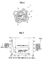
- FIG. 7 is graphs showing relationships between the ratio Da/Db of the size Da of the composite particles and the average pore diameter Db and a crystal growth ratio of CeO 2 as the first compounds and a surface area of Pt as the noble metal particles after an exhaust durability test, in which the ratio Da/Db is represented on an axis of abscissas, and the crystal growth ratio and the surface area are represented on axes of ordinates. From FIG.
- the noble metal particles 2 are made of at least one element selected from among ⁇ Pt, Pd, Rh ⁇ , and that the first compounds (anchor agent) 3 are a Ce-containing oxide which has an OSC capability and is likely to be bonded to the noble metal particles 2 (in particular, Pt) . Accordingly, it is desirable that each of the oxide containing Ce and the second compounds 4 be an oxide of at least one element selected from ⁇ Al, Zr ⁇ . Moreover, it is desirable that the oxide containing Ce be CeO 2 or a composite oxide of Ce and Zr.
- the exhaust gas purifying catalyst 1 be the one in which Pt-CeO 2 is coated with Al 2 O 3 , or the one in which Pt-CeZrO x is coated with Al 2 O 3 , more preferably, the one in which Pt-CeO 2 is coated with ZrO 2 .
- the inventors of the invention of this application found out that, when the average particle diameter of the noble metal particles 2 is 2 [nm] or less, the sintering of the noble metal particles is advanced by the movement of the noble metal particles 2 themselves, and on the contrary, when the average particle diameter of the noble metal particles 2 is 10 [nm] or more, reactivity of the noble metal particles 2 and the exhaust gas is significantly decreased. Hence, it is desirable that the average particle diameter of the noble metal particles 2 be within a range from 2 [nm] or more to 10 [nm] or less.
- the inventors of the invention of this application found out that, when a ratio of the noble metal particles 2 which contact the first compounds (anchor agent) 3 is 80[%] or less, a ratio of the noble metal particles 2 which are not present on the first compounds (anchor agent) 3 becomes 20 [%] or more, and as a result, the sintering of the noble metal particles 2 is advanced by the movement of the noble metal particles 2. Hence, it is desirable that 80 [%] or more of the noble metal particles 2 contact the first compounds (anchor agent 3).
- the transition metal compounds (TM) 5 of at least one element selected from among ⁇ Fe, Co, Ni, Mn ⁇ may be contained in the exhaust gas purifying catalyst 1.
- the element that forms the transition metal compounds 5 serves as the promoter components which further exploit the function of the noble metal particles 2. Accordingly, with such a configuration, the catalyst performance such as low-temperature activity in particular can be enhanced to a large extent.
- La may be contained in the second compounds 4.
- La has an effect of enhancing the durability of Al 2 O 3 and ZrO 2 , and accordingly, with such a configuration, heat resistance of Al 2 O 3 and ZrO 2 can be enhanced.
- an exhaust gas purifying catalyst may be composed by coating slurry containing the above-described exhaust gas purifying catalyst 1 on a fireproof inorganic support.
- FIG. 8 is an explanatory view of the production method of the exhaust gas purifying catalyst according to the present invention.
- the first step of preparing a composite colloidal solution 6 in which the noble metal particles 2 contact the first compounds 3 is performed.
- the second step of forming the second compound 4 on the peripheries of the first compounds 3 in the composite colloidal solution 6, which the noble metal particles 2 contact is performed.
- the first step it is necessary to prepare composite colloid.
- the first compounds 3 which the noble metal particles 2 contact can be suppressed from being coagulated with one another in the solution since the composite colloid concerned is uniformly dispersed into the composite colloidal solution 6.
- the first compounds 3 can be covered in advance with a dispersing protection material as will be described later, or alternatively, do not have to be covered with the dispersing protection material.
- a method of allowing the noble metal particles to contact the first compounds 3 may be reduction treatment of the noble metal particles, or may be other methods.
- the first compound 3 is covered with the dispersing protection material 7, whereby the colloid of the first compound 3 is prepared.
- a polymer compound can be used as the dispersing protection material 7.
- a solution containing the noble metal is brought into contact with the colloid of the first compound 3 covered with the dispersing protection material 7, whereby the composite colloid in which the noble metal particles 2 contact the first compound 3 is prepared.
- the dispersing protection material 7 is, for example, the polymer compound, nitric acid, acetic acid, and the like.
- FIG. 10 A description will be made of another example of the first step by using an explanatory view of FIG. 10 .
- the noble metal particles 2 are supported on the surface of the first compound 3.
- the first compound 3 on which the noble metal particles 2 are supported is covered with the dispersing protection material 7, whereby the composite colloid in which the noble metal particles 2 contact the first compound 3 is prepared.
- a method of forming the second compound 4 on the peripheries of the first compounds 3 in the second step may be the impregnation method or the inclusion method.
- a raw material of the second compound is added to the solution containing the composite colloid covered with the dispersing protection material 7, whereby a precursor 8 of the second compound 4 is formed on the periphery of the composite colloid.
- a solid content of the composite colloidal solution in which the precursor 8 of the second compound is formed is separated and fired, whereby the precursor 8 of the second compound is converted into the second compound 4.
- the above-described exhaust gas purifying catalyst 1 be produced in such a manner that the colloid of the first compounds (anchor agent) 3 is prepared by covering the first compounds (anchor agent) 3 with an average particle diameter of 30 [nm] or less with the polymer compound such as polyvinylpyrrolidone (PVP), and noble metal salt in which an average particle diameter is within the range from 2 [nm] or more to 10 [nm] or less is reduced and precipitated on the colloid of the first compounds (anchor agent) 3 by using a reducing agent such as ethanol, whereby the colloidal solution in which the noble metal particles 2 contact the first compounds (anchor agent) 3 is prepared.
- PVP polyvinylpyrrolidone
- first compounds (anchor agent) 3 with the average particle diameter of 30 [nm] or less, or the first compounds (anchor agent) 3 can be prepared by a solid-phase method, a liquid-phase method, and a gas-phase method.
- the above-described exhaust gas purifying catalyst 1 may be produced in such a manner that the colloid of the first compounds (anchor agent) 3 is prepared by covering the first compounds (anchor agent) 3 with the average particle diameter of 30 [nm] or less with the polymer compound such as the polyvinylpyrrolidone (PVP), and noble metal colloid in which an average particle diameter is within the range from 2 [nm] or more to 10 [nm] or less is brought into contact with the surface of the colloid of the first compounds (anchor agent) 3, whereby the composite colloidal solution is prepared.
- the polymer compound such as the polyvinylpyrrolidone (PVP)
- PVP polyvinylpyrrolidone
- the step may be performed, which is of dispersing organic salt of the second compounds 4 such as aluminum isopropoxide (AIP) and zirconium isopropoxide (ZIP) into an organic solvent, and then pouring the prepared colloidal solution into the organic solvent, thereby performing hydrolysis for the organic salt.
- organic salt of the second compounds 4 such as aluminum isopropoxide (AIP) and zirconium isopropoxide (ZIP)
- AIP aluminum isopropoxide
- ZIP zirconium isopropoxide
- the oxide can be disposed on the periphery of the colloid.
- the step may be performed, which is of dispersing inorganic salt as a raw material of the second compounds 4 into the solvent, peptizing the inorganic salt in the solvent by acid, and then pouring the colloidal solution into the solvent.
- the above-described raw material inorganic salt it is desirable to use boehmite when the second compounds 4 are an oxide of A1, and to use zirconium nitrate when the second compounds 4 are an oxides of Zr.
- the oxide can be disposed on the periphery of the colloid more inexpensively since the inorganic salt is more inexpensive than the organic salt.
- the production method of the exhaust gas purifying catalyst includes the step of preparing the composite colloidal solution in which the noble metal particles contact the first compounds. Moreover, the colloid of the first compounds is prepared by covering the first compounds with the average particle diameter of 30 nm or less with the polymer compound, and thereafter, the noble metal salt is reduced and precipitated on the colloid, whereby the composite colloidal solution is prepared, and so on.
- the reason for preparing the composite colloidal solution as described above is that, in general in a state where nanoparticle powder is powder, the nanoparticle powder becomes aggregates of secondary particles in which primary particles are coagulated, the aggregates of the secondary particles are coagulated and separated even if being mixed with the precursors of the second compounds in a liquid, and it is difficult to uniformly mix the aggregates and the precursors.
- the secondary particles are covered with the polymer compound to be thereby converted into the colloid and to be suppressed from being coagulated, whereby the secondary particles are not coagulated or separated even if being mixed with the precursors of the second compounds. In such a way, it is possible to obtain a catalyst in which the first compounds as the anchor agent are dispersed into the second compounds as the inclusion material.
- the catalyst can be obtained, in which the composite colloid containing the polymer compound is not used, but the secondary particles of the first compounds as the anchor agent are mixed with the precursors of the second compounds, are fired, and thereafter, are uniformly dispersed.
- the above-described production method includes: the step of milling or dispersing the aggregates in which the first compound particles with an average primary particle diameter of 30 nm or less to a secondary particle diameter of 300 nm or less; the step of supporting the noble metal particles on the secondary particles of the first compounds with the particle diameter of 300 nm or less; and the step of forming the second compounds on the peripheries of the first compounds which support the noble metal particles thereon.
- the aggregates in which the first compound particles with the average primary particle diameter of 30 nm or less are coagulated and come to have a secondary particle diameter of approximately 2 ⁇ m are milled or dispersed to the secondary particle diameter of 300 nm or less, more specifically about 100 to 300 nm, and as an example, 120 nm.
- a wet mill or disperser can be used for such milling or dispersion.
- the first compound particles milled or dispersed to the secondary particle diameter of 300 nm or less can uniformly support the noble metal particles without being coagulated one more time in the liquid.
- the first compound particles are not coagulated or separated at the time of being mixed with the precursors of the second compounds, and the catalyst in which the secondary particles of the first compounds as the anchor agent are uniformly dispersed into the catalyst after being fired can be obtained.
- the polymer compound is burnt at the time of the firing, and a temperature thereof rises locally, thus causing an apprehension that the noble metal particles may become prone to be coagulated.
- such an apprehension does not occur since the protection material composed of the polymer compound is not used.
- the polymer compound is expensive, it is advantageous not to use the protection material composed of the polymer compound as described above in terms of reducing the cost.
- the mill or the disperser which mills or disperses the aggregates in which the first compound particles with the average primary particle diameter of 30 nm or less are coagulated to the secondary particle diameter of 300 nm or less
- an arbitrary apparatus can be used as long as it is capable of milling or dispersing the particles to the diameter of 300 nm or less.
- the miller or the disperser is a beads mill, a high-speed homogenizer, a high-pressure collision mill, and the like.
- the step of supporting the noble metal particles on the secondary particles of the first compounds milled or dispersed to the particle diameter of 300 nm or less by the mill or the disperser has some specific modes.
- One of the specific modes is to first support the noble metal particles with the average particle diameter of 30 nm or less on the aggregates of the first compound particles, and to next mill or disperse the aggregates of the first compound particles on which the noble metal is supported to the secondary particle diameter of 300 nm or less by the mill or the disperser.
- the noble metal particles are supported on the secondary particles of the first compounds thus milled or dispersed to the particle diameter of 300 nm or less.
- This mode enables the secondary particles of the first compounds to be uniformly dispersed into the precursors of the second compounds.
- 100 [g/m 2 -metal] or more can be obtained in the case where the noble metal particles are Pt.
- Another one of the specific modes is to support the noble metal particles with the average particle diameter of 30 nm or less on the first compound particles during the milling or dispersing step of the aggregates of the first compound particles concerned.
- the noble metal particles are added into the mill or the disperser, whereby the noble metal particles are supported on the secondary particles of the first compounds milled or dispersed to the particle diameter of 300 nm or less.
- the noble metal particles are directly supported on the secondary particles in a state where the first compounds are milled or dispersed to the desired secondary particle diameter in the miller or the disperser.
- the noble metal particles are uniformly supported on the surfaces of the respective secondary particles of the first compounds with the secondary particle diameter of 300 nm or less.
- the activity of the catalyst is enhanced.
- 150 [g/m 2 -metal] or more can be obtained in the case where the noble metal particles are Pt.
- Timing of adding the noble metal particles may be an initial stage, middle stage or ending stage of the milling or dispersing step of the aggregates of the first compound particles by the mill or the disperser. Such adding timing just needs to be determined in response to the desired secondary particles of the first compounds.
- Another one of the specific modes is to support the noble metal particles with the average particle diameter of 30 nm or less on the secondary particles of the first compounds after milling or dispersing the noble metal particles to the secondary particle diameter of 300 nm or less.
- the noble metal particles are supported on the secondary particles of the first compounds with the secondary particle diameter of 300 nm or less in the inside of the mill or the disperser, in which the milling or the dispersion is ended, or on the outside of the mill or the disperser.
- the noble metal particles are supported on the first compounds milled or dispersed to the desired secondary particle diameter. Accordingly, the noble metal particles are uniformly supported on the surfaces of the respective secondary particles of the first compounds.
- the activity of the catalyst is enhanced.
- 150 [g/m 2 -metal] or more can be obtained in the case where the noble metal particles are Pt.
- Example 1 polyvinylpyrrolidone as surfactant was mixed into a mixed solution of water and ethanol, of which ratio was 1: 1, so as to set a ratio of the surfactant with respect to such a solvent at 0.15 [mol/L ratio], followed by stirring, and thereafter, Ce acetate was added to an obtained solution, followed by stirring. Then, after the stirring was completed, ammonia was added to the solution, followed by another stirring for two hours, whereby a colloidal solution of Ce was prepared. Next, after dinitrodiamine Pt salt was added to the colloidal solution of Ce, ethanol was added thereto, and the solution was heated up to 80 [°C], whereby Pt salt was precipitated.
- an average pore diameter of an alumina portion of this powder was measured using similar preparation treatment after excluding the Pt/CeO 2 portion.
- An average pore diameter of obtained powder was 6.2 nm.
- an average pore diameter of an alumina portion of the powder of this example is considered to have a similar numeric value.
- Example 2 Similar treatment to that of the above-described Example 1 was performed except that the ratio of the surfactant with respect to the solvent was set at 0.07 [mol/L ratio], whereby Pt, CeO 2 /Al 2 O 3 catalyst powder of Example 2 was prepared. Note that, in this catalyst powder, the average particle diameters of Pt and CeO 2 were 2.4 and 28 [nm], respectively. Moreover, the contact ratio between Pt and CeO 2 was 94[%].
- Example 3 Similar treatment to that of the above-described Example 1 was performed except that the ratio of the surfactant with respect to the solvent was set at 0.35 [mol/L ratio], whereby Pt, CeO 2 /Al 2 O 3 catalyst powder of Example 3 was prepared. Note that, in this catalyst powder, the average particle diameters of Pt and CeO 2 were 2.4 [nm] and 1 [nm], respectively. Moreover, the contact ratio between Pt and CeO 2 was 96[%].
- Example 4 the catalyst powder prepared in Example 1 by being dried in the dryer of 120[°C] was poured again into the mixed solution of the water and the ethanol, and thereafter, the dinitrodiamine Pt salt was pored into the solution. Then, after Pt was precipitated by heating the solution up to 80 [°C], the solution was fired in the air of 400[°C], whereby Pt, CeO 2 /Al 2 O 3 catalyst powder of Example 4 was prepared. Note that, with regard to a composition of this catalyst powder, Pt occupied 0.3 wt%, and CeO 2 occupied 10%.
- a ratio of an amount of Pt prepared by heating the colloidal solution of Ce added with the dinitrodiamine Pt salt and the ethanol up to 80 [°C] and an amount of Pt prepared by the step of heating the mixed solution of water and the ethanol with the dinitrodiamine Pt salt up to 80[°C] was 8: 2.
- the average particle diameters of Pt and CeO 2 were 2.4 and 7 [nm], respectively.
- the contact ratio between Pt and CeO 2 was 82[%].
- Example 5 Similar treatment to that of Example 4 was performed except that the ratio of the amount of Pt prepared by heating the colloidal solution of Ce added with the dinitrodiamine Pt salt and the ethanol up to 80[°C] and the amount of Pt prepared by the step of heating the mixed solution of water and the ethanol with the dinitrodiamine Pt salt up to 80[°C] was set at 7: 3, whereby Pt, CeO 2 /Al 2 O 3 catalyst powder of Example 5 was prepared. Note that, in this catalyst powder, the average particle diameters of Pt and CeO 2 were 2.4 and 7 [nm], respectively. Moreover, the contact ratio between Pt and CeO 2 was 75[%].
- Example 6 similar treatment to that of Example 1 was performed except that the Ce acetate was changed to mixed salt of the Ce acetate and Zr acetate in a ratio of 2: 1, whereby Pt, Ce-Zr-O x /Al 2 O 3 catalyst powder of Example 6 was prepared. Note that, in this catalyst powder, average particle diameters of Pt and Ce-Zr-O x were 2.3 and 11 [nm], respectively. Moreover, a contact ratio between Pt and Ce-Zr-O x was 93[%].
- Example 7 Similar treatment to that of Example 1 was performed except that the aluminum isopropoxide was changed to zirconium isopropoxide, whereby Pt, CeO 2 /ZrO 2 catalyst powder of Example 7 was prepared. Note that, in this catalyst powder, the average particle diameters of Pt and CeO 2 were 2.2 and 7 [nm], respectively. Moreover, the contact ratio between Pt and CeO 2 was 94[%].
- Example 8 Similar treatment to that of Example 1 was performed except that La acetate was further added to the hexylene glycol solution after the Pt salt was poured thereinto, whereby Pt, CeO 2 /Al 2 O 3 +La catalyst powder of Example 8 was prepared.
- Pt occupied 0.3 wt%
- CeO 2 occupied 10%
- La-Al 2 O 3 occupied 3 wt%.
- the average particle diameters of Pt and CeO 2 were 2.3 and 7 [nm], respectively.
- the contact ratio between Pt and CeO 2 was 94[%].
- Example 9 Similar treatment to that of Example 8 was performed except that the aluminum isopropoxide was changed to zirconium isopropoxide, whereby Pt, CeO 2 /ZrO 2 +La catalyst powder of Example 9 was prepared.
- Pt occupied 0.3 wt%
- CeO 2 occupied 10%
- ZrO 2 +La occupied 3 wt%.
- the average particle diameters of Pt and CeO 2 were 2.2 and 7 [nm], respectively.
- the contact ratio between Pt and CeO 2 was 92[%].
- Example 10 Similar treatment to that of Example 1 was performed except that the dinitrodiamine Pt salt was changed to Pd nitrate salt, whereby Pd, CeO 2 /Al 2 O 3 catalyst powder of Example 10 was prepared. Note that, in this catalyst powder, average particle diameters of Pd and CeO 2 were 3.5 and 7 [nm], respectively. Furthermore, a contact ratio between Pd and CeO 2 was 91[%].
- Example 11 Similar treatment to that of Example 1 was performed except that the dinitrodiamine Pt salt was changed to Rh nitrate salt, whereby Rh, CeO 2 /ZrO 2 catalyst powder of Example 11 was prepared. Note that, in this catalyst powder, average particle diameters of Rh and CeO 2 were 2.1 and 7 [nm], respectively. Furthermore, a contact ratio between Rh and CeO 2 . was 92 [%] .
- Example 20 Similar treatment to that of the above-described Example 1 was performed except that the ratio of the surfactant with respect to the solvent was set at 0.04 [mol/L ratio], whereby Pt, CeO 2 /Al 2 O 3 catalyst powder of Example 20 was prepared. Note that, in this catalyst powder, the average particle diameters of Pt and CeO 2 were 2.3 and 35 [nm], respectively. Furthermore, the contact ratio between Pt and CeO 2 was 94[%].
- Example 21 Similar treatment to that of the above-described Example 1 was performed except that the ethanol was not added at the time of precipitating the Pt salt, whereby Pt, CeO 2 /Al 2 O 3 catalyst powder of Example 21 was prepared. Note that, in this catalyst powder, the average particle diameters of Pt and CeO 2 were 1.5 [nm] or less and 7 [nm], respectively. Furthermore, the contact ratio between Pt and CeO 2 was 94[%].
- Example 22 Similar treatment to that of the above-described Example 1 was performed except that a commercially available aqueous solution of ceria colloidal sol was used instead of preparing the Ce colloidal solution, and that the noble metal precipitation step was not performed, whereby Pt, CeO 2 /Al 2 O 3 catalyst powder of Example 22 was prepared. Note that, in this catalyst powder, the average particle diameters of Pt and CeO 2 were 1.5 [nm] or less and 48 [nm], respectively. Moreover, the contact ratio between Pt and CeO 2 was 95[%].
- Example 23 an aqueous solution of the dinitrodiamine Pt was impregnated into and supported on commercially available nanoceria powder with an average particle diameter of 50 nm, and a resultant was dried and fired once, and thereafter, powder of Pt (0.3%) /ceria was obtained.
- the obtained powder was poured once into ion exchange water, and the polyvinylpyrrolidone was poured as the surfactant thereinto while irradiating an ultrasonic wave thereonto and suspending the obtained powder. Then, a resultant solution was stirred and mixed until the above-described components were uniformly mixed. In such a way, a powder-dispersed colloidal solution in which the average particle diameter of the ceria was 50 nm was obtained.
- Example 24 similar treatment to that of the above-described Example 1 was performed except that a Ce colloidal solution obtained by adding CeO 2 with an average particle diameter of 2.5 ⁇ m, which was milled by the ball mill, was prepared, and that Pt was supported thereon without being subjected to the reduction treatment, whereby Pt, CeO 2 /Al 2 O 3 catalyst powder of Example 24 was prepared. Note that, in this catalyst powder, the average particle diameters of Pt and CeO 2 were 1.5 [nm] or less and 2500 [nm], respectively. Moreover, the contact ratio between Pt and CeO 2 was 82[%].
- Example 25 similar treatment to that of the above-described Example 1 was performed except that a Ce colloidal solution was prepared so that the ratio of the surfactant with respect to the solvent could be 0.0015 [mol/L ratio], that a noble metal supporting concentration thereof was set at 3.0%, and that Pt was supported thereon without being subjected to the reduction treatment, whereby Pt, CeO 2 /Al 2 O 3 catalyst powder of Example 25 was prepared. Note that, in this catalyst powder, the average particle diameters of Pt and CeO 2 were 1.5 [nm] or less and 500 [nm], respectively. Moreover, the contact ratio between Pt and CeO 2 was 73[%].
- Comparative example 1 an aqueous solution of the Ce nitrate was impregnated into and supported on active alumina, and a resultant was dried at 120°C, and was then fired in an airflow for one hour, whereby CeO 2 -supported alumina powder was obtained. Then, an aqueous solution of the dinitrodiamine Pt was further impregnated into and supported on the powder thus obtained, whereby catalyst powder of Comparative example 1 was obtained. In this powder, the amount of Pt is 0.3 wt%, and the amount of CeO 2 is 10%. Note that, in this catalyst powder, the average particle diameters of Pt and CeO 2 were 1.5 [nm] or less and 600 [nm], respectively. Moreover, the contact ratio between Pt and CeO 2 was 11[%].
- Example 12 first, the polyvinylpyrrolidone as the surfactant was mixed into the mixed solution of the water and the ethanol, of which ratio was 1: 1, so as to set the ratio of the surfactant with respect to the solvent at 0.15 [mol/L ratio], followed by stirring, and thereafter, the Ce acetate was added to an obtained solution, followed by stirring. Then, after the stirring was completed, the ammonia was added to the solution, followed by another stirring for two hours, whereby the colloidal solution of Ce was prepared. Next, after the dinitrodiamine Pt salt was added to the colloidal solution of Ce, the ethanol was added thereto, and the solution was heated up to 80 [°C], whereby the Pt salt was precipitated.
- Example 13 first, the polyvinylpyrrolidone as the surfactant was mixed into the mixed solution of the water and the ethanol, of which ratio was 1: 1, so as to set the ratio of the surfactant with respect to the solvent at 0.15 [mol/L ratio], followed by stirring, and thereafter, the Ce acetate was added to an obtained solution, followed by stirring. Then, after the stirring was completed, the ammonia was added to the solution, followed by another stirring for two hours, whereby the colloidal solution of Ce was prepared. Moreover, Pt colloid with an average particle diameter of 2 [nm] was added to the colloidal solution of Ce, whereby the Pt salt was precipitated.
- Example 14 first, the polyvinylpyrrolidone as the surfactant was mixed into the mixed solution of the water and the ethanol, of which ratio was 1: 1, so as to set the ratio of the surfactant with respect to the solvent at 0.15 [mol/L ratio], followed by stirring, and thereafter, the Ce acetate was added to an obtained solution, followed by stirring. Then, after the stirring was completed, the ammonia was added to the solution, followed by another stirring for two hours, whereby the colloidal solution of Ce was prepared. Moreover, the Pt colloid with the average particle diameter of 2 [nm] was added to the colloidal solution of Ce.
- Example 15 180 [g] of the catalyst powder of Example 1, 20 [g] of alumina sol, 290 [g] of water and 10 [g] of nitric acid were poured into a magnetic ball mill, and were mixed and milled, whereby catalyst slurry was prepared. Then, the catalyst slurry was adhered onto a cordierite monolithic support (0.12 L, 400 cells), excessive slurry in the cells was removed by an airflow, followed by drying at 130[°C] and firing thereafter at 400[°C], whereby an exhaust gas purifying catalyst of Example 15 with a coated layer of 100 [g/L] was prepared.
- a cordierite monolithic support (0.12 L, 400 cells
- Example 16 Fe nitrate was impregnated into the catalyst of Example 15, whereby an exhaust gas purifying catalyst of Example 16 was prepared.
- Example 17 similar treatment to that of Example 16 was performed except that the Fe nitrate was changed to Co nitrate, whereby an exhaust gas purifying catalyst of Example 17 was prepared.
- Example 18 Similar treatment to that of Example 16 was performed except that the Fe nitrate was changed to Ni nitrate, whereby an exhaust gas purifying catalyst of Example 18 was prepared.
- Example 19 similar treatment to that of Example 16 was performed except that the Fe nitrate was changed to Mn nitrate, whereby an exhaust gas purifying catalyst of Example 19 was prepared.
- Comparative example 2 similar treatment to that of Example 15 was performed except that the catalyst powder of Comparative example 1 was used instead of the catalyst powder of Example 1, whereby an exhaust gas purifying catalyst of Comparative example 2 was prepared.
- Example 26 first, the polyvinylpyrrolidone as the surfactant was mixed into the mixed solution of the water and the ethanol, of which ratio was 1: 1, so as to set the ratio of the surfactant with respect to the solvent at 0.15 [mol/L ratio], followed by stirring, and thereafter, the Ce acetate was added to an obtained solution, followed by stirring. Then, after the stirring was completed, the ammonia was added to the solution, followed by another stirring for two hours, whereby the colloidal solution of Ce was prepared. Next, after the dinitrodiamine Pt salt was added to the colloidal solution of Ce, the ethanol was added thereto, and the solution was heated up to 80 [°C], whereby the Pt salt was precipitated.
- the above-described colloidal solution was poured into an aqueous solution in which the boehmite was dispersed. Then, after the solution was dried under reduced pressure in the evaporator, the solution was further dried in the dryer of 120[°C], whereby catalyst powder was prepared. Then, finally, the catalyst powder was fired in the air of 400[°C], whereby Pt, CeO 2 /Al 2 O 3 catalyst powder of Example 26 was prepared.
- the average pore diameter of an alumina portion of this powder was 20. 6 nm.
- the average pore diameter of an alumina portion of the powder of this example is considered to have a similar numeric value.
- Example 27 the aqueous solution of the dinitrodiamine Pt was impregnated into and supported on commercially available nanoceria powder with an average particle diameter of 101 nm, and a resultant was dried and fired once, and thereafter, powder of Pt (0.3%)/ceria powder was obtained.
- the obtained powder was poured once into the ion exchange water, and the polyvinylpyrrolidone was poured as the surfactant thereinto while irradiating the ultrasonic wave thereonto and suspending the obtained powder. Then, a resultant solution was stirred and mixed until the above-described components were uniformly mixed. In such a way, a powder-dispersed colloidal solution in which the average particle diameter of the ceria was 101 nm was obtained.
- the above-described colloidal solution was poured into the aqueous solution in which the boehmite was dispersed. Then, after the solution was dried under reduced pressure in the evaporator, the solution was further dried in the dryer of 120[°C], whereby catalyst powder was prepared. Then, finally, the catalyst powder was fired in the air of 400[°C], whereby Pt, CeO 2 /Al 2 O 3 catalyst powder of Example 27 was prepared.
- Example 28 the aqueous solution of the dinitrodiamine Pt was impregnated into and supported on the commercially available nanoceria powder with an average particle diameter of 101 nm, and a resultant was dried and fired once, and thereafter, powder of Pt (0.3%) /ceria powder was obtained.
- the obtained powder was poured once into the ion exchange water, and the polyvinylpyrrolidone was poured as the surfactant thereinto while irradiating the ultrasonic wave thereonto and suspending the obtained powder. Then, a resultant solution was stirred and mixed until the above-described components were uniformly mixed. In such a way, a powder-dispersed colloidal solution in which the average particle diameter of the ceria was 101 nm was obtained.
- the above-described colloidal solution was poured into the aqueous solution in which the boehmite was dispersed. Then, after the solution was dried under reduced pressure in the evaporator, the solution was further dried in the dryer of 120[°C], whereby catalyst powder was prepared. Then, finally, the catalyst powder was fired in the air of 400[°C], whereby Pt, CeO 2 /Al 2 O 3 catalyst powder of Example 28 was prepared.
- the average pore diameter of an alumina portion of this powder was 20. 6 nm.
- the average pore diameter of an alumina portion of the powder of this example is considered to have a similar numeric value.
- Example 29 is an example where, in producing the exhaust gas purifying catalyst, the aggregates of the secondary particles of the first compounds were dispersed by using the disperser, whereby the exhaust gas purifying catalyst was produced without preparing the composite colloidal solution.
- Example 29 is an example where the aggregates of the secondary particles of the first compounds were dispersed by the disperser after the noble metal particles were supported thereon.
- Ce-Zr-O x compound powder was dispersed into water, and a nitric acidic solution of the dinitrodiamine Pt was dropped thereonto, followed by stirring. Subsequently, a resultant was subjected to evaporation to dryness, and was thereafter fired in an airflow at 400°C for one hour. Powder obtained by the firing was the aggregates of the noble metal particles and the secondary particles of the first compounds, and an average particle diameter thereof was 2 ⁇ m.
- the obtained powder was dispersed by a commercially available beads mill (bead diameter: 0.3 mm), and the average particle diameter thereof was set at 120 nm.
- Slurry containing the dispersed secondary particles and boehmite slurry peptized by a nitric acid solution in advance were mixed together, and were stirred strongly by the homogenizer and the like. Such mixed slurry after being stirred was dried by spray dry and the like.
- Powder obtained by the drying was fired in an airflow at 550°C for three hours, whereby a Pt/CeO 2 /Al 2 O 3 catalyst was obtained.
- Example 30 is an example where, in producing the exhaust gas purifying catalyst, the aggregates of the secondary particles of the first compounds were dispersed by using the disperser, whereby the exhaust gas purifying catalyst was produced without preparing the composite colloidal solution.
- Example 30 is an example where the noble metal particles were supported on the first compounds after the aggregates of the secondary particles of the first compounds were dispersed.
- powder of the Ce-Zr-O x compound was dispersed into water, and was dispersed to approximately 120 nm by the commercially available beads mill (bead diameter: 0.3 mm).
- the nitric acidic solution of the dinitrodiamine Pt was dropped into the beads mill, and a resultant mixture was further dispersed.
- Slurry containing the dispersed secondary particles and the boehmite slurry peptized by the nitric acid solution in advance were mixed together, and were stirred strongly by the homogenizer. Such mixed slurry after being stirred was dried by the spray dry and the like.
- Powder obtained by the drying was fired in an airflow at 550°C for three hours, whereby a Pt/CeO 2 /Al 2 O 3 catalyst was obtained.
- Example 31 is an example where, in producing the exhaust gas purifying catalyst, the aggregates of the secondary particles of the first compounds were dispersed by using the disperser, whereby the exhaust gas purifying catalyst was produced without preparing the composite colloidal solution. Moreover, Example 31 is an example where the noble metal particles were supported on the first compounds after the aggregates of the secondary particles of the first compounds were dispersed. Furthermore, Example 31 is an example where the above-described supporting of the noble metal particles was performed outside of the disperser.
- the powder of the Ce-Zr-O x compound was dispersed into water, and was dispersed to approximately 120 nm by the commercially available beads mill (bead diameter: 0.3 mm). After the dispersion, obtained slurry was moved to a beaker, and was stirred continuously. The nitric acidic solution of the dinitrodiamine Pt was dropped into the beaker, and was further stirred continuously.
- the slurry containing the dispersed secondary particles and the boehmite slurry peptized by the nitric acid solution in advance were mixed together, and were stirred strongly by the homogenizer and the like. Such mixed slurry after being stirred was dried by the spray dry and the like.
- Powder obtained by the drying was fired in an airflow at 550°C for three hours, whereby a Pt/CeO 2 /Al 2 O 3 catalyst was obtained.
- Example 32 is an example where, in producing the exhaust gas purifying catalyst, the aggregates of the secondary particles of the first compounds were dispersed by using the disperser, whereby the exhaust gas purifying catalyst was produced without preparing the composite colloidal solution.
- Example 32 is an example where, before the aggregates of the secondary particles of the first compounds were dispersed, the noble metal particles were added into the disperser, and were supported on the first compounds while dispersing the first compounds in the disperser.
- powder of the Zr-La-O x compound was dispersed into water, and was poured into the commercially available beads mill (bead diameter: 0.3 mm) .
- the nitric acidic solution of the dinitrodiamine Pt was added into the beads mill in a similar way, and was dispersed to approximately 120 nm in the beads mill.
- Slurry containing the dispersed secondary particles and the boehmite slurry peptized by the nitric acid solution in advance were mixed together, and were stirred strongly by the homogenizer and the like. Such mixed slurry after being stirred was dried by spray dry and the like.
- Powder obtained by the drying was fired in an airflow at 550°C for three hours, whereby a Pt/CeO 2 /Al 2 O 3 catalyst was obtained.
- the ratio of the noble metal that contacts the first compounds is 80[%] or less
- the sintering of the noble metal is advanced as compared with the other examples. From this fact, it is understood that, desirably, 80[%] or more of the noble metal contacts the first compounds in order to further maintain the effect of enhancing the activity of the noble metal by the first compounds.
- the compound of at least one element selected from among ⁇ Fe, Co, Ni, Mn ⁇ is contained in the exhaust gas purifying catalyst, a decreasing rate of the HC conversion rate after the durability test is low as compared with the case where the compound of the above-described element is not contained as in the exhaust gas purifying catalyst of Example 15. From this fact, it is understood that, desirably, the compound of the at least one element selected from among ⁇ Fe, Co, Ni, Mn ⁇ is contained in the exhaust gas purifying catalyst in order to further maintain the effect of enhancing the activity of the noble metal by the first compounds.
- La is contained in the second compounds as in the catalyst powders of Example 8 and Example 9, a variation of the noble metal particle diameter before and after the durability test is small as compared with the case where La is not contained therein. From this fact, it is understood that, recommendably, La is contained in the second compounds in order to further enhance the effect of enhancing the activity of the noble metal by the first compounds.
- Example 15 and Examples 26 to 28 the average particle diameter Da of the composite particles of the first compounds which support the noble metal particles thereon, the average pore diameter Db of the pores formed in the second compounds, the ratio of the size Da of the composite particles and the average pore diameter Db, crystal growing properties of the second compounds after the durability test, and ⁇ HC, were investigated.
- the second particles were heated to 300°C to be subjected to degassing treatment, and an ambient atmosphere was vacuum-deaerated until a pressure thereof reached 1 ⁇ m Hg, thereby removing adsorbed water from the second particles. Moreover, the measurement was performed by an N 2 adsorption method.
- crystal growth (crystallite diameter after durability test)/(initial crystallite diameter).
- An X-ray diffraction apparatus made by MAX Science was used as a measurement instrument, and the measurement was performed under the following conditions: X-ray wavelength: CuK ⁇ ; scanning method: continuous method; measurement range: 5° to 90°; sampling interval: 0.02; scanning speed: 4°/min; voltage: 40 kV; current: 300 mA; divergence slit: 1.0°; scattering slit: 1.0°; and receiving slit: 0.3 mm.
- Example 15 and Examples 26 to 28 are superior in ⁇ HC to Comparative example 2.
- Example 15 and Example 28 in which the ratio of Da/Db is 10 or more, the movement and coagulation of the first compounds are suppressed, and accordingly, the crystal growing properties of the second compounds are small, and more excellent exhaust gas purification characteristics are imparted.
- each of the exhaust gas purifying catalysts was heated up to 400°C at a rate of 10°C/min in a gas flow with 100% of He, and subsequently, was subjected to oxidation treatment for 15 minutes in a gas flow with 100% of O 2 . Subsequently, each of the exhaust gas purifying catalysts was purged with gas of 100% of He for 5 minutes, and was subjected to reduction treatment for 15 minutes in a gas flow with 40% of H 2 and the rest of He.
- each of the exhaust gas purifying catalysts was cooled down to 50°C in a gas flow with 100% of He.
Landscapes
- Chemical & Material Sciences (AREA)
- Engineering & Computer Science (AREA)
- Chemical Kinetics & Catalysis (AREA)
- Materials Engineering (AREA)
- Organic Chemistry (AREA)
- Environmental & Geological Engineering (AREA)
- Health & Medical Sciences (AREA)
- Biomedical Technology (AREA)
- Combustion & Propulsion (AREA)
- Analytical Chemistry (AREA)
- General Chemical & Material Sciences (AREA)
- Oil, Petroleum & Natural Gas (AREA)
- Catalysts (AREA)
- Exhaust Gas Treatment By Means Of Catalyst (AREA)
- Exhaust Gas After Treatment (AREA)
- Dispersion Chemistry (AREA)
Priority Applications (1)
| Application Number | Priority Date | Filing Date | Title |
|---|---|---|---|
| EP17185069.6A EP3308846A1 (fr) | 2005-11-01 | 2006-10-31 | Catalyseur de purification de gaz d'échappement et son procédé de production |
Applications Claiming Priority (3)
| Application Number | Priority Date | Filing Date | Title |
|---|---|---|---|
| JP2005318370 | 2005-11-01 | ||
| JP2006045790 | 2006-02-22 | ||
| PCT/JP2006/321696 WO2007052627A1 (fr) | 2005-11-01 | 2006-10-31 | Pot catalytique pour épuration des gaz d’échappement et processus de fabrication idoine |
Related Child Applications (2)
| Application Number | Title | Priority Date | Filing Date |
|---|---|---|---|
| EP17185069.6A Division EP3308846A1 (fr) | 2005-11-01 | 2006-10-31 | Catalyseur de purification de gaz d'échappement et son procédé de production |
| EP17185069.6A Division-Into EP3308846A1 (fr) | 2005-11-01 | 2006-10-31 | Catalyseur de purification de gaz d'échappement et son procédé de production |
Publications (3)
| Publication Number | Publication Date |
|---|---|
| EP1955765A1 true EP1955765A1 (fr) | 2008-08-13 |
| EP1955765A4 EP1955765A4 (fr) | 2012-10-17 |
| EP1955765B1 EP1955765B1 (fr) | 2020-12-30 |
Family
ID=38005779
Family Applications (2)
| Application Number | Title | Priority Date | Filing Date |
|---|---|---|---|
| EP06822625.7A Active EP1955765B1 (fr) | 2005-11-01 | 2006-10-31 | Procédé de fabrication d'un catalyseur pour épuration des gaz d échappement |
| EP17185069.6A Withdrawn EP3308846A1 (fr) | 2005-11-01 | 2006-10-31 | Catalyseur de purification de gaz d'échappement et son procédé de production |
Family Applications After (1)
| Application Number | Title | Priority Date | Filing Date |
|---|---|---|---|
| EP17185069.6A Withdrawn EP3308846A1 (fr) | 2005-11-01 | 2006-10-31 | Catalyseur de purification de gaz d'échappement et son procédé de production |
Country Status (6)
| Country | Link |
|---|---|
| US (2) | US8404611B2 (fr) |
| EP (2) | EP1955765B1 (fr) |
| JP (5) | JP4562776B2 (fr) |
| KR (1) | KR100989269B1 (fr) |
| CN (1) | CN101400441B (fr) |
| WO (1) | WO2007052627A1 (fr) |
Cited By (25)
| Publication number | Priority date | Publication date | Assignee | Title |
|---|---|---|---|---|
| EP1980318A3 (fr) * | 2007-04-12 | 2011-06-22 | Nissan Motor Co., Ltd. | Catalyseur de purification de gaz d'échappement et son procédé de fabrication |
| EP2014361A4 (fr) * | 2006-04-28 | 2012-10-17 | Nissan Motor | Catalyseur de purification de gaz d'echappement et son procede de production |
| US8309487B2 (en) | 2008-07-16 | 2012-11-13 | Nissan Motor Co., Ltd. | Exhaust gas purifying catalyst and method for producing the same |
| EP2404668A4 (fr) * | 2009-03-04 | 2013-04-17 | Nissan Motor | Catalyseur de purification de gaz d'échappement et procédé de production associé |
| US8609578B2 (en) | 2008-07-31 | 2013-12-17 | Nissan Motor Co., Ltd. | Exhaust gas purifying catalyst |
| US8683787B2 (en) | 2009-11-17 | 2014-04-01 | Nissan Motor Co., Ltd. | Exhaust gas purifying catalyst and method for manufacturing the same |
| JP2014079717A (ja) * | 2012-10-18 | 2014-05-08 | Nissan Motor Co Ltd | 排気ガス浄化用触媒及びその製造方法 |
| EP2512664A4 (fr) * | 2009-12-15 | 2014-05-28 | Sdcmaterails Inc | Catalyseurs perfectionnés pour applications automobiles |
| EP2512657A4 (fr) * | 2009-12-15 | 2014-06-04 | Sdcmaterails Inc | Procédé de formation d'un catalyseur à mobilité inhibée à base d'un matériau nano-actif |
| EP2140937A4 (fr) * | 2007-04-20 | 2014-07-23 | Nissan Motor | Catalyseur extrêmement résistant à la chaleur et procédé pour la production de celui-ci |
| EP2213372A4 (fr) * | 2007-11-08 | 2014-07-23 | Nissan Motor | Procédé de production d'une poudre chargée de métal noble, poudre chargée de métal noble et catalyseur de purification des gaz d'échappement |
| US8859035B1 (en) | 2009-12-15 | 2014-10-14 | SDCmaterials, Inc. | Powder treatment for enhanced flowability |
| US8969237B2 (en) | 2011-08-19 | 2015-03-03 | SDCmaterials, Inc. | Coated substrates for use in catalysis and catalytic converters and methods of coating substrates with washcoat compositions |
| US9023754B2 (en) | 2005-04-19 | 2015-05-05 | SDCmaterials, Inc. | Nano-skeletal catalyst |
| US9089840B2 (en) | 2007-10-15 | 2015-07-28 | SDCmaterials, Inc. | Method and system for forming plug and play oxide catalysts |
| US9149797B2 (en) | 2009-12-15 | 2015-10-06 | SDCmaterials, Inc. | Catalyst production method and system |
| US9156025B2 (en) | 2012-11-21 | 2015-10-13 | SDCmaterials, Inc. | Three-way catalytic converter using nanoparticles |
| RU2567859C2 (ru) * | 2009-12-15 | 2015-11-10 | ЭсДиСиМАТИРИАЛЗ, ИНК. | Способ формирования катализатора с ингибированной подвижностью наноактивного материала |
| US9216406B2 (en) | 2011-02-23 | 2015-12-22 | SDCmaterials, Inc. | Wet chemical and plasma methods of forming stable PtPd catalysts |
| EP2308595A4 (fr) * | 2008-07-04 | 2016-01-27 | Nissan Motor | Catalyseur de purification des gaz d échappement |
| US9427732B2 (en) | 2013-10-22 | 2016-08-30 | SDCmaterials, Inc. | Catalyst design for heavy-duty diesel combustion engines |
| US9511352B2 (en) | 2012-11-21 | 2016-12-06 | SDCmaterials, Inc. | Three-way catalytic converter using nanoparticles |
| US9517448B2 (en) | 2013-10-22 | 2016-12-13 | SDCmaterials, Inc. | Compositions of lean NOx trap (LNT) systems and methods of making and using same |
| US9586179B2 (en) | 2013-07-25 | 2017-03-07 | SDCmaterials, Inc. | Washcoats and coated substrates for catalytic converters and methods of making and using same |
| US9687811B2 (en) | 2014-03-21 | 2017-06-27 | SDCmaterials, Inc. | Compositions for passive NOx adsorption (PNA) systems and methods of making and using same |
Families Citing this family (14)
| Publication number | Priority date | Publication date | Assignee | Title |
|---|---|---|---|---|
| EP1955765B1 (fr) | 2005-11-01 | 2020-12-30 | Nissan Motor Co., Ltd. | Procédé de fabrication d'un catalyseur pour épuration des gaz d échappement |
| JP2008188542A (ja) | 2007-02-06 | 2008-08-21 | Mitsubishi Heavy Ind Ltd | 排ガス処理用触媒、その製造方法および排ガス処理方法 |
| CN105935590A (zh) * | 2008-08-27 | 2016-09-14 | 优美科催化剂日本有限公司 | 废气净化用催化剂以及使用此催化剂的废气净化方法 |
| JP6262413B2 (ja) * | 2009-03-06 | 2018-01-17 | ユミコア日本触媒株式会社 | 排気ガス浄化用触媒及びその製造方法、並びに排気ガス浄化方法 |
| US20110143930A1 (en) * | 2009-12-15 | 2011-06-16 | SDCmaterials, Inc. | Tunable size of nano-active material on nano-support |
| US9266092B2 (en) | 2013-01-24 | 2016-02-23 | Basf Corporation | Automotive catalyst composites having a two-metal layer |
| WO2016123534A1 (fr) * | 2015-01-29 | 2016-08-04 | Basf Corporation | Catalyseurs à métal du groupe du platine (pgm) pour traitement des émissions automobiles |
| JP2020500097A (ja) * | 2016-10-12 | 2020-01-09 | ビーエーエスエフ コーポレーション | 触媒物品 |
| JP7119256B2 (ja) * | 2017-07-05 | 2022-08-17 | 地方独立行政法人東京都立産業技術研究センター | Voc処理用触媒の製造方法、voc処理方法及びvoc処理用触媒 |
| KR102322704B1 (ko) * | 2018-09-27 | 2021-11-04 | (주)엘엑스하우시스 | 배기가스 정화용 촉매 |
| CN111185155B (zh) * | 2018-11-14 | 2021-08-31 | 中国科学院大连化学物理研究所 | 一种负载-包覆型贵金属催化剂及其制备和应用 |
| GB201901560D0 (en) * | 2019-02-05 | 2019-03-27 | Magnesium Elektron Ltd | Zirconium based dispersion for use in coating filters |
| US12320288B2 (en) * | 2019-10-18 | 2025-06-03 | Umicore Shokubai Japan Co., Ltd. | Exhaust gas purification catalyst, method of purifying exhaust gas, and method of manufacturing exhaust gas purification catalyst |
| CN116116445B (zh) * | 2021-11-12 | 2025-05-23 | 北京市科学技术研究院资源环境研究所 | 一种臭氧氧化催化剂及其制备方法和原位再生方法 |
Family Cites Families (21)
| Publication number | Priority date | Publication date | Assignee | Title |
|---|---|---|---|---|
| JPH05309272A (ja) * | 1992-05-08 | 1993-11-22 | Mitsubishi Heavy Ind Ltd | 酸化触媒の製造方法 |
| JP3371531B2 (ja) * | 1994-04-20 | 2003-01-27 | 株式会社豊田中央研究所 | 触媒の製造方法 |
| JPH08131830A (ja) | 1994-11-07 | 1996-05-28 | Toyota Motor Corp | 排ガス浄化用触媒 |
| JPH08309183A (ja) * | 1995-05-18 | 1996-11-26 | Babcock Hitachi Kk | 高耐熱性触媒およびその製造方法 |
| JP2000015097A (ja) * | 1998-06-30 | 2000-01-18 | Toyota Motor Corp | 触媒の製造方法 |
| GB9824152D0 (en) | 1998-11-05 | 1998-12-30 | Univ Warwick | New product |
| JP3861647B2 (ja) | 2001-10-09 | 2006-12-20 | トヨタ自動車株式会社 | 排ガス浄化用触媒 |
| JP3855266B2 (ja) * | 2001-11-01 | 2006-12-06 | 日産自動車株式会社 | 排気ガス浄化用触媒 |
| US7341976B2 (en) * | 2002-10-16 | 2008-03-11 | Conocophillips Company | Stabilized boehmite-derived catalyst supports, catalysts, methods of making and using |
| US8444945B2 (en) * | 2002-12-26 | 2013-05-21 | Idemitsu Kosan Co., Ltd. | Method for removing sulfur compound in hydrocarbon-containing gas |
| DE602004007187T3 (de) * | 2003-05-21 | 2017-09-28 | Toyota Jidosha Kabushiki Kaisha | Verfahren zur Herstellung eines porösen Mischoxids |
| JP4196745B2 (ja) | 2003-06-12 | 2008-12-17 | トヨタ自動車株式会社 | 排ガス浄化用触媒 |
| JP4193601B2 (ja) * | 2003-06-12 | 2008-12-10 | トヨタ自動車株式会社 | 排ガス浄化用触媒 |
| JP4175186B2 (ja) | 2003-06-12 | 2008-11-05 | トヨタ自動車株式会社 | 排ガス浄化用触媒とその製造方法 |
| JP2005097642A (ja) * | 2003-09-22 | 2005-04-14 | Tanaka Kikinzoku Kogyo Kk | 貴金属−金属酸化物複合クラスター |
| JP2005111336A (ja) * | 2003-10-06 | 2005-04-28 | Nissan Motor Co Ltd | 耐熱性触媒およびその製造方法 |
| JP4296908B2 (ja) * | 2003-11-21 | 2009-07-15 | 株式会社デンソー | 触媒体およびその製造方法 |
| JP3912377B2 (ja) * | 2003-12-25 | 2007-05-09 | 日産自動車株式会社 | 排ガス浄化用触媒粉末の製造方法 |
| JP3855994B2 (ja) * | 2003-12-25 | 2006-12-13 | 日産自動車株式会社 | 触媒及びその製造方法 |
| JP2005185969A (ja) * | 2003-12-25 | 2005-07-14 | Nissan Motor Co Ltd | 高耐熱性触媒及びその製造方法 |
| EP1955765B1 (fr) | 2005-11-01 | 2020-12-30 | Nissan Motor Co., Ltd. | Procédé de fabrication d'un catalyseur pour épuration des gaz d échappement |
-
2006
- 2006-10-31 EP EP06822625.7A patent/EP1955765B1/fr active Active
- 2006-10-31 EP EP17185069.6A patent/EP3308846A1/fr not_active Withdrawn
- 2006-10-31 WO PCT/JP2006/321696 patent/WO2007052627A1/fr not_active Ceased
- 2006-10-31 JP JP2007542740A patent/JP4562776B2/ja active Active
- 2006-10-31 KR KR1020087013096A patent/KR100989269B1/ko active Active
- 2006-10-31 US US12/084,382 patent/US8404611B2/en active Active
- 2006-10-31 CN CN200680041213.2A patent/CN101400441B/zh active Active
-
2009
- 2009-08-19 JP JP2009190530A patent/JP5346740B2/ja active Active
-
2010
- 2010-03-10 JP JP2010053001A patent/JP2010155244A/ja active Pending
-
2012
- 2012-12-03 JP JP2012264055A patent/JP5613219B2/ja active Active
-
2013
- 2013-02-19 US US13/770,344 patent/US9073044B2/en active Active
-
2014
- 2014-03-19 JP JP2014056278A patent/JP5792853B2/ja active Active
Cited By (52)
| Publication number | Priority date | Publication date | Assignee | Title |
|---|---|---|---|---|
| US9599405B2 (en) | 2005-04-19 | 2017-03-21 | SDCmaterials, Inc. | Highly turbulent quench chamber |
| US9132404B2 (en) | 2005-04-19 | 2015-09-15 | SDCmaterials, Inc. | Gas delivery system with constant overpressure relative to ambient to system with varying vacuum suction |
| US9216398B2 (en) | 2005-04-19 | 2015-12-22 | SDCmaterials, Inc. | Method and apparatus for making uniform and ultrasmall nanoparticles |
| US9023754B2 (en) | 2005-04-19 | 2015-05-05 | SDCmaterials, Inc. | Nano-skeletal catalyst |
| US9180423B2 (en) | 2005-04-19 | 2015-11-10 | SDCmaterials, Inc. | Highly turbulent quench chamber |
| US9719727B2 (en) | 2005-04-19 | 2017-08-01 | SDCmaterials, Inc. | Fluid recirculation system for use in vapor phase particle production system |
| EP2014361A4 (fr) * | 2006-04-28 | 2012-10-17 | Nissan Motor | Catalyseur de purification de gaz d'echappement et son procede de production |
| EP1980318A3 (fr) * | 2007-04-12 | 2011-06-22 | Nissan Motor Co., Ltd. | Catalyseur de purification de gaz d'échappement et son procédé de fabrication |
| EP2140937A4 (fr) * | 2007-04-20 | 2014-07-23 | Nissan Motor | Catalyseur extrêmement résistant à la chaleur et procédé pour la production de celui-ci |
| US9302260B2 (en) | 2007-10-15 | 2016-04-05 | SDCmaterials, Inc. | Method and system for forming plug and play metal catalysts |
| US9737878B2 (en) | 2007-10-15 | 2017-08-22 | SDCmaterials, Inc. | Method and system for forming plug and play metal catalysts |
| US9597662B2 (en) | 2007-10-15 | 2017-03-21 | SDCmaterials, Inc. | Method and system for forming plug and play metal compound catalysts |
| US9592492B2 (en) | 2007-10-15 | 2017-03-14 | SDCmaterials, Inc. | Method and system for forming plug and play oxide catalysts |
| US9089840B2 (en) | 2007-10-15 | 2015-07-28 | SDCmaterials, Inc. | Method and system for forming plug and play oxide catalysts |
| US9186663B2 (en) | 2007-10-15 | 2015-11-17 | SDCmaterials, Inc. | Method and system for forming plug and play metal compound catalysts |
| EP2213372A4 (fr) * | 2007-11-08 | 2014-07-23 | Nissan Motor | Procédé de production d'une poudre chargée de métal noble, poudre chargée de métal noble et catalyseur de purification des gaz d'échappement |
| EP2308595A4 (fr) * | 2008-07-04 | 2016-01-27 | Nissan Motor | Catalyseur de purification des gaz d échappement |
| US8309487B2 (en) | 2008-07-16 | 2012-11-13 | Nissan Motor Co., Ltd. | Exhaust gas purifying catalyst and method for producing the same |
| US8609578B2 (en) | 2008-07-31 | 2013-12-17 | Nissan Motor Co., Ltd. | Exhaust gas purifying catalyst |
| US8486853B2 (en) | 2009-03-04 | 2013-07-16 | Nissan Motor Co., Ltd. | Exhaust gas purifying catalyst and method for manufacturing the same |
| EP2404668A4 (fr) * | 2009-03-04 | 2013-04-17 | Nissan Motor | Catalyseur de purification de gaz d'échappement et procédé de production associé |
| US8683787B2 (en) | 2009-11-17 | 2014-04-01 | Nissan Motor Co., Ltd. | Exhaust gas purifying catalyst and method for manufacturing the same |
| US8906498B1 (en) | 2009-12-15 | 2014-12-09 | SDCmaterials, Inc. | Sandwich of impact resistant material |
| US9522388B2 (en) | 2009-12-15 | 2016-12-20 | SDCmaterials, Inc. | Pinning and affixing nano-active material |
| EP2512664A4 (fr) * | 2009-12-15 | 2014-05-28 | Sdcmaterails Inc | Catalyseurs perfectionnés pour applications automobiles |
| US9149797B2 (en) | 2009-12-15 | 2015-10-06 | SDCmaterials, Inc. | Catalyst production method and system |
| EP2512657A4 (fr) * | 2009-12-15 | 2014-06-04 | Sdcmaterails Inc | Procédé de formation d'un catalyseur à mobilité inhibée à base d'un matériau nano-actif |
| US9126191B2 (en) | 2009-12-15 | 2015-09-08 | SDCmaterials, Inc. | Advanced catalysts for automotive applications |
| US8992820B1 (en) | 2009-12-15 | 2015-03-31 | SDCmaterials, Inc. | Fracture toughness of ceramics |
| US8859035B1 (en) | 2009-12-15 | 2014-10-14 | SDCmaterials, Inc. | Powder treatment for enhanced flowability |
| US9308524B2 (en) | 2009-12-15 | 2016-04-12 | SDCmaterials, Inc. | Advanced catalysts for automotive applications |
| US9332636B2 (en) | 2009-12-15 | 2016-05-03 | SDCmaterials, Inc. | Sandwich of impact resistant material |
| US8932514B1 (en) | 2009-12-15 | 2015-01-13 | SDCmaterials, Inc. | Fracture toughness of glass |
| US9533289B2 (en) | 2009-12-15 | 2017-01-03 | SDCmaterials, Inc. | Advanced catalysts for automotive applications |
| RU2567859C2 (ru) * | 2009-12-15 | 2015-11-10 | ЭсДиСиМАТИРИАЛЗ, ИНК. | Способ формирования катализатора с ингибированной подвижностью наноактивного материала |
| US9433938B2 (en) | 2011-02-23 | 2016-09-06 | SDCmaterials, Inc. | Wet chemical and plasma methods of forming stable PTPD catalysts |
| EP2678267A4 (fr) * | 2011-02-23 | 2018-01-31 | SDC Materials, Inc. | Procédé chimique par voie humide pour former des oxydes diesel ptpd stables |
| US9216406B2 (en) | 2011-02-23 | 2015-12-22 | SDCmaterials, Inc. | Wet chemical and plasma methods of forming stable PtPd catalysts |
| US8969237B2 (en) | 2011-08-19 | 2015-03-03 | SDCmaterials, Inc. | Coated substrates for use in catalysis and catalytic converters and methods of coating substrates with washcoat compositions |
| US9498751B2 (en) | 2011-08-19 | 2016-11-22 | SDCmaterials, Inc. | Coated substrates for use in catalysis and catalytic converters and methods of coating substrates with washcoat compositions |
| JP2014079717A (ja) * | 2012-10-18 | 2014-05-08 | Nissan Motor Co Ltd | 排気ガス浄化用触媒及びその製造方法 |
| US9156025B2 (en) | 2012-11-21 | 2015-10-13 | SDCmaterials, Inc. | Three-way catalytic converter using nanoparticles |
| US9533299B2 (en) | 2012-11-21 | 2017-01-03 | SDCmaterials, Inc. | Three-way catalytic converter using nanoparticles |
| US9511352B2 (en) | 2012-11-21 | 2016-12-06 | SDCmaterials, Inc. | Three-way catalytic converter using nanoparticles |
| US9586179B2 (en) | 2013-07-25 | 2017-03-07 | SDCmaterials, Inc. | Washcoats and coated substrates for catalytic converters and methods of making and using same |
| US9517448B2 (en) | 2013-10-22 | 2016-12-13 | SDCmaterials, Inc. | Compositions of lean NOx trap (LNT) systems and methods of making and using same |
| US9427732B2 (en) | 2013-10-22 | 2016-08-30 | SDCmaterials, Inc. | Catalyst design for heavy-duty diesel combustion engines |
| US9566568B2 (en) | 2013-10-22 | 2017-02-14 | SDCmaterials, Inc. | Catalyst design for heavy-duty diesel combustion engines |
| US9950316B2 (en) | 2013-10-22 | 2018-04-24 | Umicore Ag & Co. Kg | Catalyst design for heavy-duty diesel combustion engines |
| US9687811B2 (en) | 2014-03-21 | 2017-06-27 | SDCmaterials, Inc. | Compositions for passive NOx adsorption (PNA) systems and methods of making and using same |
| US10086356B2 (en) | 2014-03-21 | 2018-10-02 | Umicore Ag & Co. Kg | Compositions for passive NOx adsorption (PNA) systems and methods of making and using same |
| US10413880B2 (en) | 2014-03-21 | 2019-09-17 | Umicore Ag & Co. Kg | Compositions for passive NOx adsorption (PNA) systems and methods of making and using same |
Also Published As
| Publication number | Publication date |
|---|---|
| US20130157844A1 (en) | 2013-06-20 |
| JP5346740B2 (ja) | 2013-11-20 |
| CN101400441A (zh) | 2009-04-01 |
| JP2014144458A (ja) | 2014-08-14 |
| EP3308846A1 (fr) | 2018-04-18 |
| EP1955765B1 (fr) | 2020-12-30 |
| JP2010005617A (ja) | 2010-01-14 |
| JP2013052391A (ja) | 2013-03-21 |
| WO2007052627A1 (fr) | 2007-05-10 |
| JP2010155244A (ja) | 2010-07-15 |
| JP5792853B2 (ja) | 2015-10-14 |
| EP1955765A4 (fr) | 2012-10-17 |
| JP5613219B2 (ja) | 2014-10-22 |
| US20090111688A1 (en) | 2009-04-30 |
| KR100989269B1 (ko) | 2010-10-20 |
| US8404611B2 (en) | 2013-03-26 |
| JP4562776B2 (ja) | 2010-10-13 |
| KR20080068898A (ko) | 2008-07-24 |
| US9073044B2 (en) | 2015-07-07 |
| CN101400441B (zh) | 2014-12-31 |
| JPWO2007052627A1 (ja) | 2009-04-30 |
Similar Documents
| Publication | Publication Date | Title |
|---|---|---|
| EP1955765B1 (fr) | Procédé de fabrication d'un catalyseur pour épuration des gaz d échappement | |
| EP2452750B1 (fr) | Catalyseur de purification de gaz d échappement et procédé de production associé | |
| EP1944082B1 (fr) | Catalyseur de purification de gaz d'échappement et son procédé de fabrication | |
| EP1839749B1 (fr) | Catalyseur, catalyseur de purification de gaz d'echappement et procede de fabrication du catalyseur | |
| EP2022562B1 (fr) | Catalyseur de purification de gaz d'échappement | |
| JP4547935B2 (ja) | 排ガス浄化用触媒、排ガス浄化触媒、及び触媒の製造方法 | |
| JP7838835B2 (ja) | 貴金属が単独原子状態で担持された三元触媒の調製方法及び使用 | |
| EP2893979B1 (fr) | Catalyseur de purification de gaz d'échappement, catalyseur monolithique de purification de gaz d'échappement et procédé de fabrication de catalyseur de purification de gaz d'échappement | |
| EP1839745A1 (fr) | Catalyseur de purification de gaz d'echappement et procede pour le produire | |
| US20070167319A1 (en) | Heat-resistive catalyst and production method thereof | |
| EP3581268A1 (fr) | Composition de catalyseur d'épuration de gaz d'échappement, son procédé de fabrication, et catalyseur d'épuration de gaz d'échappement pour automobiles | |
| WO2014024312A1 (fr) | Catalyseur de purification de gaz d'échappement et son procédé de fabrication | |
| WO2018088201A1 (fr) | Catalyseur à trois voies de purification de gaz d'échappement, son procédé de fabrication, et convertisseur de catalyseur de purification de gaz d'échappement | |
| JP3722060B2 (ja) | 触媒体及び触媒体の製造方法並びにその触媒体を用いた排気ガス浄化用触媒 | |
| EP4360743A1 (fr) | Catalyseur de purification de gaz d'échappement | |
| JP2007144290A (ja) | 排ガス浄化触媒及び排ガス浄化触媒の製造方法 | |
| JP4779271B2 (ja) | 触媒 | |
| JP2008221217A (ja) | 排ガス浄化用触媒及びその製造方法 | |
| JP5104009B2 (ja) | 排気ガス浄化触媒及びその製造方法 | |
| JP2006142137A (ja) | 排ガス浄化用触媒及びその製造方法 | |
| JP2005230780A (ja) | 排気ガス浄化触媒およびその製造方法 | |
| JP2021065818A (ja) | 排気ガス浄化用触媒、排気ガスの浄化方法、及び排気ガス浄化用触媒の製造方法 | |
| JP2007029779A (ja) | 排ガス浄化触媒 |
Legal Events
| Date | Code | Title | Description |
|---|---|---|---|
| PUAI | Public reference made under article 153(3) epc to a published international application that has entered the european phase |
Free format text: ORIGINAL CODE: 0009012 |
|
| 17P | Request for examination filed |
Effective date: 20080521 |
|
| AK | Designated contracting states |
Kind code of ref document: A1 Designated state(s): DE FR GB |
|
| RBV | Designated contracting states (corrected) |
Designated state(s): DE FR GB |
|
| DAX | Request for extension of the european patent (deleted) | ||
| A4 | Supplementary search report drawn up and despatched |
Effective date: 20120919 |
|
| RIC1 | Information provided on ipc code assigned before grant |
Ipc: B01J 23/63 20060101ALI20120913BHEP Ipc: B01D 53/94 20060101AFI20120913BHEP Ipc: B01J 23/89 20060101ALI20120913BHEP Ipc: B01J 35/00 20060101ALI20120913BHEP Ipc: B01J 23/656 20060101ALI20120913BHEP |
|
| 17Q | First examination report despatched |
Effective date: 20130410 |
|
| STAA | Information on the status of an ep patent application or granted ep patent |
Free format text: STATUS: EXAMINATION IS IN PROGRESS |
|
| REG | Reference to a national code |
Ref country code: DE Ref legal event code: R079 Ref document number: 602006059871 Country of ref document: DE Free format text: PREVIOUS MAIN CLASS: B01J0023630000 Ipc: B01D0053940000 |
|
| GRAP | Despatch of communication of intention to grant a patent |
Free format text: ORIGINAL CODE: EPIDOSNIGR1 |
|
| STAA | Information on the status of an ep patent application or granted ep patent |
Free format text: STATUS: GRANT OF PATENT IS INTENDED |
|
| RIC1 | Information provided on ipc code assigned before grant |
Ipc: B01J 35/00 20060101ALI20200925BHEP Ipc: B01J 37/03 20060101ALI20200925BHEP Ipc: B01D 53/94 20060101AFI20200925BHEP Ipc: B01J 23/63 20060101ALI20200925BHEP Ipc: B01J 37/02 20060101ALI20200925BHEP Ipc: B01J 23/656 20060101ALI20200925BHEP Ipc: B01J 23/89 20060101ALI20200925BHEP |
|
| INTG | Intention to grant announced |
Effective date: 20201014 |
|
| GRAS | Grant fee paid |
Free format text: ORIGINAL CODE: EPIDOSNIGR3 |
|
| GRAA | (expected) grant |
Free format text: ORIGINAL CODE: 0009210 |
|
| STAA | Information on the status of an ep patent application or granted ep patent |
Free format text: STATUS: THE PATENT HAS BEEN GRANTED |
|
| AK | Designated contracting states |
Kind code of ref document: B1 Designated state(s): DE FR GB |
|
| RAP1 | Party data changed (applicant data changed or rights of an application transferred) |
Owner name: NISSAN MOTOR CO., LTD. Owner name: RENAULT S.A.S. |
|
| REG | Reference to a national code |
Ref country code: GB Ref legal event code: FG4D |
|
| RIN1 | Information on inventor provided before grant (corrected) |
Inventor name: SHIRATORI, KAZUYUKI Inventor name: IKEZAWA, JUN Inventor name: AOYAMA, MAKOTO Inventor name: WAKAMATSU, HIRONORI Inventor name: YASUDA, HIROFUMI Inventor name: NAKAMURA, MASANORI Inventor name: SUGA, KATSUO |
|
| REG | Reference to a national code |
Ref country code: DE Ref legal event code: R096 Ref document number: 602006059871 Country of ref document: DE |
|
| REG | Reference to a national code |
Ref country code: DE Ref legal event code: R097 Ref document number: 602006059871 Country of ref document: DE |
|
| PLBE | No opposition filed within time limit |
Free format text: ORIGINAL CODE: 0009261 |
|
| STAA | Information on the status of an ep patent application or granted ep patent |
Free format text: STATUS: NO OPPOSITION FILED WITHIN TIME LIMIT |
|
| 26N | No opposition filed |
Effective date: 20211001 |
|
| PGFP | Annual fee paid to national office [announced via postgrant information from national office to epo] |
Ref country code: GB Payment date: 20250923 Year of fee payment: 20 |
|
| PGFP | Annual fee paid to national office [announced via postgrant information from national office to epo] |
Ref country code: FR Payment date: 20250923 Year of fee payment: 20 |
|
| PGFP | Annual fee paid to national office [announced via postgrant information from national office to epo] |
Ref country code: DE Payment date: 20250923 Year of fee payment: 20 |