EP1955770A2 - Mikrofluidische Vorrichtung auf Zentrifugalkraftbasis zur Verdünnung und mikrofluidisches System damit - Google Patents
Mikrofluidische Vorrichtung auf Zentrifugalkraftbasis zur Verdünnung und mikrofluidisches System damit Download PDFInfo
- Publication number
- EP1955770A2 EP1955770A2 EP08151025A EP08151025A EP1955770A2 EP 1955770 A2 EP1955770 A2 EP 1955770A2 EP 08151025 A EP08151025 A EP 08151025A EP 08151025 A EP08151025 A EP 08151025A EP 1955770 A2 EP1955770 A2 EP 1955770A2
- Authority
- EP
- European Patent Office
- Prior art keywords
- valve
- platform
- mixing chamber
- microfluidic device
- energy source
- Prior art date
- Legal status (The legal status is an assumption and is not a legal conclusion. Google has not performed a legal analysis and makes no representation as to the accuracy of the status listed.)
- Withdrawn
Links
Images






Classifications
-
- B—PERFORMING OPERATIONS; TRANSPORTING
- B01—PHYSICAL OR CHEMICAL PROCESSES OR APPARATUS IN GENERAL
- B01L—CHEMICAL OR PHYSICAL LABORATORY APPARATUS FOR GENERAL USE
- B01L3/00—Containers or dishes for laboratory use, e.g. laboratory glassware; Droppers
- B01L3/50—Containers for the purpose of retaining a material to be analysed, e.g. test tubes
- B01L3/502—Containers for the purpose of retaining a material to be analysed, e.g. test tubes with fluid transport, e.g. in multi-compartment structures
- B01L3/5027—Containers for the purpose of retaining a material to be analysed, e.g. test tubes with fluid transport, e.g. in multi-compartment structures by integrated microfluidic structures, i.e. dimensions of channels and chambers are such that surface tension forces are important, e.g. lab-on-a-chip
- B01L3/502738—Containers for the purpose of retaining a material to be analysed, e.g. test tubes with fluid transport, e.g. in multi-compartment structures by integrated microfluidic structures, i.e. dimensions of channels and chambers are such that surface tension forces are important, e.g. lab-on-a-chip characterised by integrated valves
-
- G—PHYSICS
- G01—MEASURING; TESTING
- G01N—INVESTIGATING OR ANALYSING MATERIALS BY DETERMINING THEIR CHEMICAL OR PHYSICAL PROPERTIES
- G01N37/00—Details not covered by any other group of this subclass
-
- B—PERFORMING OPERATIONS; TRANSPORTING
- B01—PHYSICAL OR CHEMICAL PROCESSES OR APPARATUS IN GENERAL
- B01L—CHEMICAL OR PHYSICAL LABORATORY APPARATUS FOR GENERAL USE
- B01L3/00—Containers or dishes for laboratory use, e.g. laboratory glassware; Droppers
- B01L3/50—Containers for the purpose of retaining a material to be analysed, e.g. test tubes
- B01L3/502—Containers for the purpose of retaining a material to be analysed, e.g. test tubes with fluid transport, e.g. in multi-compartment structures
- B01L3/5027—Containers for the purpose of retaining a material to be analysed, e.g. test tubes with fluid transport, e.g. in multi-compartment structures by integrated microfluidic structures, i.e. dimensions of channels and chambers are such that surface tension forces are important, e.g. lab-on-a-chip
- B01L3/50273—Containers for the purpose of retaining a material to be analysed, e.g. test tubes with fluid transport, e.g. in multi-compartment structures by integrated microfluidic structures, i.e. dimensions of channels and chambers are such that surface tension forces are important, e.g. lab-on-a-chip characterised by the means or forces applied to move the fluids
-
- B—PERFORMING OPERATIONS; TRANSPORTING
- B01—PHYSICAL OR CHEMICAL PROCESSES OR APPARATUS IN GENERAL
- B01L—CHEMICAL OR PHYSICAL LABORATORY APPARATUS FOR GENERAL USE
- B01L3/00—Containers or dishes for laboratory use, e.g. laboratory glassware; Droppers
- B01L3/50—Containers for the purpose of retaining a material to be analysed, e.g. test tubes
- B01L3/502—Containers for the purpose of retaining a material to be analysed, e.g. test tubes with fluid transport, e.g. in multi-compartment structures
- B01L3/5027—Containers for the purpose of retaining a material to be analysed, e.g. test tubes with fluid transport, e.g. in multi-compartment structures by integrated microfluidic structures, i.e. dimensions of channels and chambers are such that surface tension forces are important, e.g. lab-on-a-chip
- B01L3/502769—Containers for the purpose of retaining a material to be analysed, e.g. test tubes with fluid transport, e.g. in multi-compartment structures by integrated microfluidic structures, i.e. dimensions of channels and chambers are such that surface tension forces are important, e.g. lab-on-a-chip characterised by multiphase flow arrangements
- B01L3/502784—Containers for the purpose of retaining a material to be analysed, e.g. test tubes with fluid transport, e.g. in multi-compartment structures by integrated microfluidic structures, i.e. dimensions of channels and chambers are such that surface tension forces are important, e.g. lab-on-a-chip characterised by multiphase flow arrangements specially adapted for droplet or plug flow, e.g. digital microfluidics
- B01L3/502792—Containers for the purpose of retaining a material to be analysed, e.g. test tubes with fluid transport, e.g. in multi-compartment structures by integrated microfluidic structures, i.e. dimensions of channels and chambers are such that surface tension forces are important, e.g. lab-on-a-chip characterised by multiphase flow arrangements specially adapted for droplet or plug flow, e.g. digital microfluidics for moving individual droplets on a plate, e.g. by locally altering surface tension
-
- G—PHYSICS
- G01—MEASURING; TESTING
- G01N—INVESTIGATING OR ANALYSING MATERIALS BY DETERMINING THEIR CHEMICAL OR PHYSICAL PROPERTIES
- G01N33/00—Investigating or analysing materials by specific methods not covered by groups G01N1/00 - G01N31/00
- G01N33/48—Biological material, e.g. blood, urine; Haemocytometers
- G01N33/50—Chemical analysis of biological material, e.g. blood, urine; Testing involving biospecific ligand binding methods; Immunological testing
- G01N33/53—Immunoassay; Biospecific binding assay; Materials therefor
-
- B—PERFORMING OPERATIONS; TRANSPORTING
- B01—PHYSICAL OR CHEMICAL PROCESSES OR APPARATUS IN GENERAL
- B01L—CHEMICAL OR PHYSICAL LABORATORY APPARATUS FOR GENERAL USE
- B01L2200/00—Solutions for specific problems relating to chemical or physical laboratory apparatus
- B01L2200/06—Fluid handling related problems
- B01L2200/0605—Metering of fluids
-
- B—PERFORMING OPERATIONS; TRANSPORTING
- B01—PHYSICAL OR CHEMICAL PROCESSES OR APPARATUS IN GENERAL
- B01L—CHEMICAL OR PHYSICAL LABORATORY APPARATUS FOR GENERAL USE
- B01L2200/00—Solutions for specific problems relating to chemical or physical laboratory apparatus
- B01L2200/06—Fluid handling related problems
- B01L2200/0647—Handling flowable solids, e.g. microscopic beads, cells, particles
-
- B—PERFORMING OPERATIONS; TRANSPORTING
- B01—PHYSICAL OR CHEMICAL PROCESSES OR APPARATUS IN GENERAL
- B01L—CHEMICAL OR PHYSICAL LABORATORY APPARATUS FOR GENERAL USE
- B01L2200/00—Solutions for specific problems relating to chemical or physical laboratory apparatus
- B01L2200/16—Reagents, handling or storing thereof
-
- B—PERFORMING OPERATIONS; TRANSPORTING
- B01—PHYSICAL OR CHEMICAL PROCESSES OR APPARATUS IN GENERAL
- B01L—CHEMICAL OR PHYSICAL LABORATORY APPARATUS FOR GENERAL USE
- B01L2300/00—Additional constructional details
- B01L2300/08—Geometry, shape and general structure
- B01L2300/0803—Disc shape
- B01L2300/0806—Standardised forms, e.g. compact disc [CD] format
-
- B—PERFORMING OPERATIONS; TRANSPORTING
- B01—PHYSICAL OR CHEMICAL PROCESSES OR APPARATUS IN GENERAL
- B01L—CHEMICAL OR PHYSICAL LABORATORY APPARATUS FOR GENERAL USE
- B01L2300/00—Additional constructional details
- B01L2300/08—Geometry, shape and general structure
- B01L2300/0861—Configuration of multiple channels and/or chambers in a single devices
- B01L2300/0864—Configuration of multiple channels and/or chambers in a single devices comprising only one inlet and multiple receiving wells, e.g. for separation, splitting
-
- B—PERFORMING OPERATIONS; TRANSPORTING
- B01—PHYSICAL OR CHEMICAL PROCESSES OR APPARATUS IN GENERAL
- B01L—CHEMICAL OR PHYSICAL LABORATORY APPARATUS FOR GENERAL USE
- B01L2300/00—Additional constructional details
- B01L2300/08—Geometry, shape and general structure
- B01L2300/0861—Configuration of multiple channels and/or chambers in a single devices
- B01L2300/0867—Multiple inlets and one sample wells, e.g. mixing, dilution
-
- B—PERFORMING OPERATIONS; TRANSPORTING
- B01—PHYSICAL OR CHEMICAL PROCESSES OR APPARATUS IN GENERAL
- B01L—CHEMICAL OR PHYSICAL LABORATORY APPARATUS FOR GENERAL USE
- B01L2300/00—Additional constructional details
- B01L2300/08—Geometry, shape and general structure
- B01L2300/0887—Laminated structure
-
- B—PERFORMING OPERATIONS; TRANSPORTING
- B01—PHYSICAL OR CHEMICAL PROCESSES OR APPARATUS IN GENERAL
- B01L—CHEMICAL OR PHYSICAL LABORATORY APPARATUS FOR GENERAL USE
- B01L2300/00—Additional constructional details
- B01L2300/18—Means for temperature control
- B01L2300/1861—Means for temperature control using radiation
-
- B—PERFORMING OPERATIONS; TRANSPORTING
- B01—PHYSICAL OR CHEMICAL PROCESSES OR APPARATUS IN GENERAL
- B01L—CHEMICAL OR PHYSICAL LABORATORY APPARATUS FOR GENERAL USE
- B01L2400/00—Moving or stopping fluids
- B01L2400/04—Moving fluids with specific forces or mechanical means
- B01L2400/0403—Moving fluids with specific forces or mechanical means specific forces
- B01L2400/0409—Moving fluids with specific forces or mechanical means specific forces centrifugal forces
-
- B—PERFORMING OPERATIONS; TRANSPORTING
- B01—PHYSICAL OR CHEMICAL PROCESSES OR APPARATUS IN GENERAL
- B01L—CHEMICAL OR PHYSICAL LABORATORY APPARATUS FOR GENERAL USE
- B01L2400/00—Moving or stopping fluids
- B01L2400/06—Valves, specific forms thereof
- B01L2400/0677—Valves, specific forms thereof phase change valves; Meltable, freezing, dissolvable plugs; Destructible barriers
Definitions
- the present invention relates to a centrifugal force based microfluidic device, and more particularly, to a microfluidic device which can automatically perform dilution of a sample in a microfluidic structure disposed on a disk type platform, and a microfluidic system including the microfluidic device.
- a driving pressure is generally required to transfer the fluid within a microfluidic device.
- Capillary pressure or a pressure generated by a specifically prepared pump is used as the driving pressure.
- a lab compact disk (CD) or a lab-on a disk is a recently-suggested microfluidic device obtained by arranging microfluidic structures on a compact disk-shaped platform and uses centrifugal force.
- a lab CD or a lab-on a disk since a microfluidic structure is not fixed to a frame to revolve, a lab CD or a lab-on a disk is different from a lab-on-a chip, in which a microfluidic structure is fixed to the bottom, in various aspects.
- U.S. Patent Publication Nos. 5,836,004 and 6,705,357 disclose devices which can provide samples having various concentrations on microfluidic chips. However, since electro-osmosis is used in U.S. Patent Publication No. 5,836,004 , a high driving voltage is required. U.S. Patent Publication No. 6,705,357 cannot provide an exponential function type concentration gradient. In addition, it is difficult to embody the devices on a disk type platform.
- the present invention provides a centrifugal force based microfluidic device for dilution which can provide samples having various concentrations without additional manual processes except for a process in which a sample is initially injected.
- the present invention also provides a microfluidic system including the microfluidic device.
- a centrifugal force based microfluidic device for dilution including a rotatable disk type platform; a mixing chamber disposed on the platform; a buffer solution storage disposed on a portion of the platform which is closer to a center of the platform than the mixing chamber, connected to the mixing chamber through a channel to supply a predetermined amount of buffer solution to the mixing chamber at least one time; and a plurality of diluted solution chambers which are disposed on a portion of the platform which is farther from the center of the platform than the mixing chamber, are each connected to the mixing chamber through flow paths extended from a middle exit corresponding to a predetermined water level, and sequentially receiving a solution which is diluted in the mixing chamber at least one time.
- the microfluidic device may further include a sample storage disposed on a portion of the platform which is closer to the center of the platform than the mixing chamber, and which supplies a sample injected from the outside to the mixing chamber using a centrifugal force.
- the buffer storage may include a metering chamber having a number of exit valves each of which is located corresponding to each of the number of water levels and is independently driven, and each of the water levels corresponds to n times a predetermined buffer volume, where n is a natural number.
- the buffer solution storage may include a plurality of buffer chambers comprising exit valves each of which are independently driven, and each having the same volume.
- the valve or the valve group may include a valve material in which a heating particle dispersed in a phase transition material dispersion medium which is solid at a room temperature, and a transition valve operated using an operation in which the valve material is melted by heat generated by electromagnetic waves emitted from an external energy source and moved, and the channel is opened and closed.
- the valve group may include a pair of phase transition valves comprising a normally closed valve and a normally open valve.
- the phase transition material dispersion medium may be at least one selected from the group consisting of wax, gel and a thermoplastic resin.
- the diameter of the heating particle may be in the range of 1 nm to 100 ⁇ m.
- the heating particle may be formed of at least one selected from the group consisting of a polymer bead, a quantum dot, an Au nanoparticle, an Ag nanoparticle, a bead with metal composition, a carbon particle and a magnetic bead.
- a centrifugal force based microfluidic system including a microfluidic device for dilution comprising a rotatable disk type platform, a mixing chamber disposed on the platform, a buffer solution storage disposed on a portion of the platform which is closer to a center of the platform than the mixing chamber, connected to the mixing chamber through a channel to supply a predetermined amount of buffer solution to the mixing chamber at least one time, and a plurality of diluted solution chambers which are disposed on a portion of the platform which is farther from the center of the platform than the mixing chamber, are each connected to the mixing chamber through flow paths extended from a middle exit corresponding to a predetermined water level, and sequentially receives a solution which is diluted in the mixing chamber at least one time; a revolution driving unit revolve so as to support and control the microfluidic device; and a valve driving unit which independently drives a valve selected in the microfluidic device.
- the valve driving unit may include an external energy source emitting an electromagnetic wave having a wavelength band such that heating particles in the valve are heated; and an external energy source controller controlling a location and a direction of the external energy source such that an electromagnetic wave emitted by the external energy source is intensively incident on a region corresponding to the selected valve.
- the external energy source controller may include a straight moving unit moving the external energy source facing the platform of the microfluidic device in a radial direction of the platform.
- the external energy source supplier may include a plane moving unit moving the external energy source facing the platform of the microfluidic device in two directions on a plane parallel to the platform with respect to rectangular coordinates.
- the microfluidic system may further include a sample storage disposed on the platform,such that the sample storage is disposed closer to the center of the platform than the mixing chamber, and supplying a sample injected from the outside by a centrifugal force.
- the buffer storage may include a metering chamber having a number of exit valves each of which is located corresponding to each of the number of water levels and is independently driven, and each of the water levels corresponds to n times a predetermined buffer volume, where n is a natural number.
- the buffer solution storage may include a plurality of buffer solution chambers comprising exit valves, which are independently driven and have same volumes.
- a valve or a valve group which independently open and closes the diluted solution chambers, may be installed in each of the flow paths connected from the middle exit of the mixing chamber to the diluted solution chambers.
- the valve or the valve group may include a valve material in which a heating particle dispersed in a phase transition material dispersion medium which is solid at a room temperature, and a transition valve operated using an operation in which the valve material is melted by heat generated by electromagnetic waves emitted from an external energy source and moved, and the channel is opened and closed.
- the valve group may include a pair of phase transition valves comprising a normally closed and a normally open valve.
- the diameter of the heating particle may be in the range of 1 nm to 100 ⁇ m.
- the heating particle may be formed of at least one selected from the group consisting of a polymer bead, a quantum dot, an Au nanoparticle, an Ag nanoparticle, a bead with metal composition, a carbon particle and a magnetic bead.
- a flow path of this specification includes at least one channels as a path through which a fluid flows so as to connect chambers that are different from one another.
- an exit valve is a valve controlling out flow from one another. That is, the exit valve is a term relative to the location of a valve.
- a normally closed valve, a normally open valve and a reversible valve respectively are relative to the functions of phase transition valves according to embodiments of the present invention. Some valves may be both an exit valve and a normally closed valve. Valves having various shapes can be used as exit valves. For example, a normally closed valve using a phase transition material can be used as an exit valve.
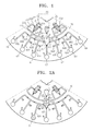
- FIG. 1 is a plan view illustrating a centrifugal force based microfluidic device for dilution according to an embodiment of the present invention.
- the microfluidic device according to the current embodiment of the present invention includes a platform 10 having a disk shape, a plurality of chambers 21 through 23, 50 and 61 through 67 disposed on the platform 10, a plurality of channels 40, 41, 43, 45 and 431 through 436 connecting the chambers 21 through 23, 50 and 61 through 67, and a plurality of valves 211, 221 through 223, 231 through 233, 611, 612, 621,622, 631, 632, 641, 642, 651, 652, 661, 662 and 671 controlling the flow of fluid through the channels 40, 41, 43, 45, 431 through 436.
- the platform 10 may be formed of a plastic material such as acryl or polydimethylsiloxane (PDMS) which are easy to mold and of which surfaces are inactive in terms of biology, but the present invention is not limited thereto. That is, the platform 10 may be formed of any material that has chemical and biological stability, optical transparency and mechanical processability.
- the platform 10 may be formed of plates in a plurality of layers. By forming engraved structures, which correspond to a chamber and a channel, on surfaces on which plates contact each other, and adhering the plates to each other, spaces and passages of the platform 10 may be provided inside the platform 10. The plates may be bonded to each other using adhesive, double-sided adhesive tape or ultrasonic fusion.
- a mixing chamber 50 for mixing a sample and a buffer solution is disposed on the platform 10.
- Each of the exit valves 221 through 223 of the metering chamber 22 is connected to the mixing chamber 50 through each of admission channels 421 through 423 and the channel 40.
- the exit valves 221 through 223 may be various valves such as capillary valves, hydrophobic valves, mechanical valves or geometric valves as well as phase transition valves which are driven by an eternal energy source.
- a capillary valve having lowest open revolutions may be used as a valve 221 corresponding to have a highest water level
- a capillary valve having highest open revolutions may be used as a valve 223 corresponding to have a lowest water level.
- the sample storage may include a sample chamber 21, and an exit valve 211 of the sample chamber 21, which controls the fluid of flow through a channel 41 connecting the sample chamber 21 with the mixing chamber 50.
- the sample storage may not be included.
- a plurality of diluted solution chambers 61 through 67 housing diluted sample solutions by concentrations are disposed on a portion of the platform 10, which is farther from the center of the platform 10 than the mixing chamber 50.
- the mixing chamber 50 is connected to each of the diluted solution chambers 61 through 66 through a channel 43 which is directly connected to a middle exit of the mixing chamber 50, and a plurality of branch channels 431 through 436 which are diverged from the channel 43 and respectively correspond to the diluted solution chambers 61 through 66.
- the diluted solution chamber 67 in which a diluted solution having the lowest concentration is to be housed, may be connected to the mixing chamber 50 through a channel 45 which is directly connected to an exit valve 671 connected to an outermost portion of the mixing chamber 50.
- FIGS. 2A through 2C are views illustrating a dilution operation using the microfluidic device of FIG. 1 , according to an embodiment of the present invention.
- the exit valve 211 of the sample chamber 21 is opened, and then a sample having an initial concentration is transferred to the mixing chamber 50 using a centrifugal force.
- the normally closed valve 611 of a flow path formed of channels 43 and 431 connected by a first diluted solution chamber 61 is opened, and then a first diluted solution (initial concentration) is transferred using a centrifugal force as indicated by an arrow 2.
- the normally open valve 612 of the first branch channel 431 connected to the first diluted solution chamber 61 is closed. At this time, a sample having a predetermined volume "R1" remains in the mixing chamber 50.
- a first exit valve 221 of the metering chamber 22 is opened, and then a buffer solution having a predetermined volume "B1" is transferred to the mixing chamber 50 and mixed as indicated by an arrow 3.
- a second diluted solution which is diluted by R1/(R1+B1) times the initial concentration of the sample, is obtained.
- a normally closed valve 621 of a flow path formed of channels 43 and 432 connected to a second diluted solution chamber 62 is opened, and then the second diluted solution is transferred using a centrifugal force as indicated by an arrow 4.
- a normally open valve 622 of the second branch channel 432 connected to the second diluted solution chamber 62 is closed. At this time, the second diluted solution having the predetermined volume "R1" also remains in the mixing chamber 50.
- a second exit valve 222 of the metering chamber 22 is opened, and then a buffer solution having the predetermined volume "B1" is transferred to the mixing chamber 50 and mixed as indicated by an arrow 5.
- a third solution which is diluted by (R1/(R1+B1)) 2 times the initial concentration of the sample, is obtained.
- a normally closed valve 631 of a flow path formed of channels 43 and 433 connected to a third diluted solution chamber 63 is opened, and then the third diluted solution is transferred using a centrifugal force as indicated by an arrow 6.
- a normally open valve 632 of a third branch channel 433 connected to the third diluted solution chamber 63 is closed. At this time, the third diluted solution having the predetermined volume "R1" also remains in the mixing chamber 50.
- the diluted solutions having various concentrations can have various uses, for example, in a standard curve or a calibration curve of a real-time PCR for cell counting or quantitative analysis of a gene.
- the microfluidic device according to the current embodiment of the present invention can be integrated on a platform together with a centrifugal force based microfluidic device performing other functions, and can easily provide resulting materials using samples of various concentrations.
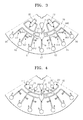
- FIG. 3 is a plan view illustrating a centrifugal force based microfluidic device for dilution according to another embodiment of the present invention.
- the centrifugal force based microfluidic device of FIG. 3 is different in terms of the type and distribution of valves controlling the flow of fluid in a plurality of flow paths which respectively connect a mixing chamber 50 with a plurality of diluted solution chambers 61 through 66.
- reversible valves 613, 623, 633, 643, 653 and 663 may be respectively installed in a plurality of branch channels 441 through 446 diverged from a channel 44 which is directly connected to each of two middle exits of the mixing chamber 50.
- Each of the reversible valves 613, 623, 633, 643, 653 and 663 is an example of a phase transition valve.
- the reversible valves 613, 623, 633, 643, 653 and 663 can perform operations such as opening and closing flow paths, and can repeat opening and closing operations of flow paths several times if necessary.
- FIG. 4 is a plan view illustrating a centrifugal force based microfluidic device for dilution according to another embodiment of the present invention.
- the centrifugal force based microfluidic device of FIG. 4 is different in terms of the shape of a buffer solution storage.
- the centrifugal force based microfluidic device according to the current embodiment of the present invention may include buffer solution chambers 24 through 29 having the number corresponding to the supplying time of buffer solutions, and exit valves 241, 251, 261, 271, 281 and 291 which are independently driven by the buffer solution chambers 24 through 29.
- the exit valves 241, 251, 261, 271, 281 and 291 may be various valves such as capillary valves and hydrophobic valves, which are opened under revolutions different from each other as well as phase transition valves (normally closed valves), which are independently driven by an external energy source.
- FIG. 5 is a plan view illustrating a centrifugal force based microfluidic device for dilution according to another embodiment of the present invention.
- the centrifugal force based microfluidic device of FIG. 5 is different in terms of the type and distribution of valves controlling the flow of fluid in a plurality of flow paths which respectively connect a mixing chamber 50 with a plurality of diluted solution chambers 61 through 66.
- each of reversible valves 601 and 602 is installed in a channel 46 which is directly connected to both middle exits of a mixing chamber 50.
- Normally open valves 612, 622, 632, 642, 652 and 662 which are independently driven, may be respectively installed in a plurality of branch channels 461 through 466 diverged from the downstream of the channel 46, which is below the reversible valves 601 and 602.
- the reversible valves 601 and 602 may repeatedly perform opening and closing at least three times.
- the valve plug 83 completely blocks without a gap a predetermined portion of the first area 43A which is not overlapped with an opening 83A and blocks the flow of fluid F flowing from an entrance "I".
- the valve plug 83 is melted at a high temperature and is moved from the first area 43A to the second areas 43B, and then the valve plug 83 is again solidified while flow paths of the fluid F is opened (See 83').
- the opening 83A functions as an injection hole which can define a valve plug by injecting a valve material melted when manufacturing the microfluidic device.
- the valve material injected into the first area 43A through the opening 83A remains in the predetermined portion of the first area 43A by capillary action.
- An external energy source (see 130L of FIG. 13 ) is disposed outside the microfluidic device 100 (see 100 of FIG. 13 ) in order to supplying heat to the valve plug 83.
- the external energy source 130L emits electromagnetic waves to a region including an initial location of the valve plug 83, that is, the opening 83A and the circumstance thereof.
- the external energy source 130L may be, for example, a laser light source emitting a laser beam, wherein the laser light source may include at least one laser diode.
- the laser light source emits a pulse laser beam
- the laser light source can emit a pulse laser beam having energy of 1 mJ/pulse or more.
- the laser light source When the laser light source emits a continuous wave laser beam, the laser light source can emit a continuous wave laser beam having power of 10 mW or more. Any laser light source emitting a laser beam having a wavelength in the range of 400 through 1300 nm can be used as the external energy source 130L of the microfluidic system.
- the channel 43 can be provided by stereoscopic patterns formed inside an upper substrate 12 or a lower substrate 11 constituting a disk type platform 10.
- the upper substrate 12 may be formed of an optically transparent material which can transmit electromagnetic waves emitted by an external energy source so that the electromagnetic waves may be incident on the valve plug 83, and by which the flow of fluid F can be seen from the outside.
- the upper substrate 12 may be preferably formed of a glass material or a transparent plastic material which has excellent optical transparency and reduced manufacturing costs.
- Heating particles dispersed on the valve plug 83 may each have a diameter in the range of 1 nm to 100 ⁇ m so as to freely flow in the channel 43 having a width of several thousands of micrometers ( ⁇ m).
- the heating particles have properties by which the temperature of the heating particles is remarkably increased when a laser is irradiated to the heating particles, and as such the heating particles emit heat.
- the heating particles have properties by which the heating particles are regularly dispersed in wax.
- the heating particles may have a structure including a core having a metal component and a shell which is water-repellant so as to have the above properties.
- the heating particles may have a structure including a core formed of Fe, which is a ferromagnetic material, and a shell formed of a plurality of surfactants coupled to the core and surrounding the core.
- the heating particles are stored to be dispersed in carrier oil.
- the carrier oil may be water-repellant so that the heating particles having a water-repellant surface structure may be regularly dispersed.
- a material used for forming the valve plug 83 may be manufactured.
- the particle shape of each of the heating particles is not limited to the above examples. That is, each of the heating particles may be a polymer bead, quantum dots, Au nanoparticles, Ag nanoparticles, beads with metal composition, carbon particles or magnetic beads.
- the carbon particles may include graphite particles.
- a phase transition material constituting the valve plug 83 may be wax. Energy of electromagnetic waves, which is absorbed by the heating particles, is transferred to the circumstance in type of thermal energy, and as such the wax is melted to have fluidity. Accordingly, the valve plug 83 is collapsed and the fluid path of fluid F is opened.
- the wax constituting the valve plug 83 may have an appropriate melting point. If the melting point of the wax is very high, since a long time is required from when a laser beam is not emitted to the wax until the wax is melted, it is difficult to minutely control an opening time. On the other hand, if the melting point of the wax is very low, since the wax may be partially melted while a laser beam is not emitted, the fluid F may be leaked.
- the wax may be, for example, paraffin wax, microcrystalline wax, synthetic wax, natural wax or the like.
- the phase transition material may be gel or a thermoplastic resin.
- the gel may be polyacrylamide, polyacrylates, polymethacrylates, polyvinylamides or the like.
- the thermoplastic resin may be cyclic olefin copolymer (COC), polymethylmethacrylate (acrylic) (PMMA), polycarbonate (PC), polystyrene (PS), polyacetal engineering polymers (POM), perfluoroalkoxy (PFA), polyvinyl chloride (PVC), polypropylene (PP), polyethylene terephthalate (PET), polyetheretherketone (PEEK), polyamide (PA), polysulfone (PSU), polyvinylidene difluoride (PVDF), or the like.
- COC cyclic olefin copolymer
- PMMA polymethylmethacrylate
- PC polycarbonate
- PS polystyrene
- POM polyacetal engineering polymers
- PFA perfluoroalkoxy
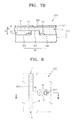
- FIG. 8 is a plan view illustrating the normally open valve 632 used in the microfluidic devices of FIGS. 1 and 3 through 5 , according to an embodiment of the present invention.
- FIG. 9 is a cross-sectional view for illustrating operations of the normally open valve 632 of FIG. 8 , according to an embodiment of the present invention.
- the normally open valve 632 includes a valve material container 85 and a valve material V.
- the valve material container 85 is connected between channels 433 having an inlet “I” and an outlet “O".
- the valve material V is filled in the valve material container 85 to be solid at an initial stage, that is, at room temperature, melted and expanded to flow into the channels 433 through a valve connecting path, and again solidified to block the channels 433.
- the normally open valve 632 may be provided a stereoscopic pattern formed inside an upper substrate 12 and a lower substrate 11 constituting a platform 10 of the microfluidic device 100 similarly to the normally closed valve 631 as described above.
- the upper substrate 12 may be formed of an optically transparent material which can transmit an electromagnetic waves emitted by an external energy source and by which the flow of fluid F can be seen from the outside.
- the upper substrate may include an opening 85A corresponding to the valve material container 85 so that the electromagnetic waves (for example, a laser beam) may be incident on the valve material V.
- the opening 85A may function as an injection hole to which a valve material melted is injected during manufacturing the microfluidic device..
- a phase transition material P constituting the valve material V and heating particles M are the same as those described with reference to the normally closed valve 631.
- the external energy source supplying electromagnetic waves to the valve material V is the same as that described above.
- valve material V When a laser beam is emitted to the valve material V solidified in the valve material container 85, the heating particles M absorb energy to heat the phase transition material P. Accordingly, while the valve material V is melted, the volume of the valve material V is expanded, and the valve material V flows into the channels 433 through the valve connecting path 86. The valve material V, which is again solidified while contacting fluid F in the channels 433, blocks the flow of fluid F passing through the channel 433.
- the results of the experiment in which response times of the normally closed valve and the normally open valve are measured, will be described.
- the pressure of operating fluid in a test chip for the experiment was maintained as 46 kPa.
- a syringe pump Havard PHD2000, USA
- a pressure sensor MPX 5500DP, Freescale semiconductor Inc., AZ, USA
- a laser light source of which emitting wave has a wavelength of 808 nm and which has power of 1.5 W, was used as an external energy source emitting electromagnetic waves to the valves.
- Data of the response time of the valves was obtained by analyzing the result of a high-speed photography device (Fastcam-1024, Photron, CA, USA).
- the valve plug may be magnetic wax in which magnetic beads, which are heating particles having an average diameter of 10 nm, are dispersed in carrier oil, and in other words, ferrofluid and paraffin wax were mixed by a ratio of 1 to 1, that is, the volume fraction of the ferrofluid is 50 %.
- the response time, from when a laser beam is emitted to a valve plug of the normally closed valve until the valve plug is solidified to open a channel, is 0.012 seconds.
- the response time, from when a laser beams is emitted to a valve material container of the valve material until the valve material is melted and expanded to close a channel is 0.444 seconds. It can be seen that the valves according to the embodiments of the present invention can be more quickly operated than a conventional wax valve in that the response time of the conventional wax valve is 2 through 10 seconds.
- FIG. 10 is a graph illustrating the relationship between the volume fraction of the ferrofluid included in the valve plug and the response time of the normally closed valve with respect to the normally closed valve of FIG. 6 .
- the volume fraction of the ferrofluid As the volume fraction of the ferrofluid is increased, the response time is roughly reduced. However, irrespective of this, when the volume fraction of the ferrofluid is increased to be 70 % or more, the maximum hold-up pressure of the valve plug has a tendency to be reduced. Accordingly, the volume fraction of the the ferrofluid to be included in the valve plug of the valve unit may be determined according to regulation between the requirement for the response time and the requirement for the maximum hold-up pressure.
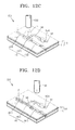
- FIGS. 12A through 12F are perspective views for illustrating operations of reversible valves 601 used in the microfluidic devices of FIGS. 3 and 5 , according to an embodiment of the present invention.
- the reversible valve 601 used in the microfluidic devices of FIGS. 3 and 5 is an example of a phase transition valve which is independently driven by en external energy source.
- the reversible valve 601 includes a valve material container 95, a valve material V injected to the valve material container 95, a valve connecting path 96 connecting the valve material container 95 with a channel 46 defining the flow path of fluid F, and a laser light source 130 which is an example of an energy source for supplying energy to the valve material V.
- the laser light source 130 emits a laser beam L which is a kind of an electromagnetic wave, but the present invention is not limited to a laser light source. That is, the energy source may emit infrared rays IR, or inject a high temperature gas to supply energy to the valve material V.
- the valve material container 95, the channel 46, and the valve connecting path 96 may be formed on a disk type platform 10 including an upper substrate 12 and a lower substrate 11 which are bonded to each other.
- the upper substrate 12 and the lower substrate 11 may be bonded using adhesive, double-sided adhesive tape or ultrasonic fusion.
- the valve material container 95, the channel 46, and the valve connecting path 96 may be engraved to be patterned on the lower substrate 11.
- An opening 95A for injecting the valve material V to the valve material container 95 is formed in the upper substrate 12.
- the channel 46 comprises a first area 46A of a first dimension D1 and a pair of second areas 46B adjacent to the first area 46A.
- the second areas 46B are of a second dimension D2 larger than D1.
- valve material V when the laser beam L is emitted to the valve material V, which is injected to the valve material container 95 for a while to be hardened, by the laser light source 130, the valve material V is explosively melted to be expanded, and flows into the first area 46A of the channel 46 through the valve connecting path 96.
- the valve material V flowing into the channel 46 proceeds by capillary action and the valve material remains in the first area 46A to be hardened, and thus a valve plug blocking the channel 46 is formed. Accordingly, the fluid F cannot flow along the channel 46 any more.
- the hardened valve material V is again explosively melted to be expanded.
- the valve material V flows into the first area 46A.
- the valve material V remains in the first area 46A to be hardened in the first area 46A, thus again closing the channel 46.
- the laser beam L is repeatedly emitted until the valve material V is mostly in the second areas 46B of the channel 46, and thus the channel 46 can be repeatedly opened and closed.
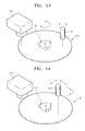
- FIG. 13 is a perspective view illustrating a microfluidic system including one of the microfluidic devices of FIGS. 1 and 3 through 5 , according to an embodiment of the present invention.
- the microfluidic system according to the current embodiment of the present invention includes the microfluidic device 100 described above.
- the microfluidic system includes an external energy source 130L emitting predetermined electromagnetic waves to supply energy to valves using a phase transition material which are independently driven as described above.
- the external energy source 130L may be a device which can emit electromagnetic waves having a predetermined wavelength band, such as microwaves, infrared rays, visible rays, ultraviolet rays or X-rays, preferably, a device which can intensively emit the electromagnetic waves to a short-distance target.
- the wavelength of waves generated by the external energy source 130L may be in the range such that the waves may be not well absorbed by the heating particles M included in the valve material V. Accordingly, a device generating electromagnetic waves from the external energy source 130L may be appropriately selected according to the materials and surface conditions of the heating particles M.
- the external energy source 130L may be, for example, a laser light source emitting a laser beam. At this time, the laser light source may include at least one laser diode. Details such as the wavelength and the power of the laser beam may be determined according to the kinds of the heating particles included in the phase transition valve of the microfluidic device 100 which is mainly used objective.
- the microfluidic system includes an external energy source controller (not shown) such that electromagnetic waves emitted from the external energy source 130L may be intensively incident on a desired region of the microfluidic device 100, more particularly, a region corresponding to any one of a plurality of phase transition valves included in the microfluidic device 100 by controlling the location and the direction of the external energy source 130L.
- the external energy source controller can move the external energy source 130L facing the platform 10 of the microfluidic device 100 in an arrow direction indicated over the microfluidic device 100, that is, a radial direction of the platform 10.
- the external energy source 130L may be moved in a straight direction using different mechanisms. Those mechanisms are obvious to those of ordinary skill in the art, and thus descriptions thereof will not be included.
- the microfluidic system includes a revolution driving unit 140 driving the platform 10.
- the revolution driving unit 140 stabilizes the platform 10, and is an element for transmitting rotary power.
- the revolution driving unit 140 may include a motor and a related component thereof, which can revolve the platform 10 by a desired velocity or angular rotation.
- the external energy source 130L can intensively emit electromagnetic waves to a selected region of the microfluidic device 100 by help of the external energy source controller and the revolution driving unit 140.
- the microfluidic system may further include a light detector 150 by which results of various experiments using the concentration of a diluted solution and diluted solutions, which are results of serial dilution using the microfluidic device 100, can be optically observed. For example, by observing each of the diluted solution chambers 61 through 67 using the light detector 150 during the serial dilution of a dyed cell solution, the concentration of the diluted cell solution can be inspected.
- an external energy source controller may include a plane moving unit such that the external energy source 130P facing the platform 10 may be moved in two directions perpendicular to each other (for example, directions of x and y axes, refer to arrows) on a plane parallel to the platform 10, and electromagnetic waves may be emitted to an objective target on the platform 10.
- the external energy source controller may be configured such that the emitted electromagnetic waves may reach an objective target by changing the direction of the eternal energy source of which location is fixed at a predetermined point over the platform 10.
- the microfluidic device for dilution and the microfluidic system including the microfluidic device can automatically provide samples having various concentrations without additional manual processes except for a manual step in which a sample is initially injected. Since the serial dilution used in the present invention can provide higher precision than conventional serial dilution using manual processes, concentration error can be reduced. In addition, when the microfluidic device for serial dilution and the microfluidic system including the microfluidic device are used in an automated lab-on-a disk for quantitative analysis of genes, a calibrator sample can be automatically provided.
Landscapes
- Chemical & Material Sciences (AREA)
- Health & Medical Sciences (AREA)
- Dispersion Chemistry (AREA)
- Analytical Chemistry (AREA)
- General Health & Medical Sciences (AREA)
- Hematology (AREA)
- Clinical Laboratory Science (AREA)
- Chemical Kinetics & Catalysis (AREA)
- Life Sciences & Earth Sciences (AREA)
- Immunology (AREA)
- Engineering & Computer Science (AREA)
- Molecular Biology (AREA)
- Physics & Mathematics (AREA)
- Pathology (AREA)
- General Physics & Mathematics (AREA)
- Biomedical Technology (AREA)
- Urology & Nephrology (AREA)
- Biochemistry (AREA)
- Microbiology (AREA)
- Cell Biology (AREA)
- Biotechnology (AREA)
- Food Science & Technology (AREA)
- Medicinal Chemistry (AREA)
- Automatic Analysis And Handling Materials Therefor (AREA)
- Mixers With Rotating Receptacles And Mixers With Vibration Mechanisms (AREA)
Applications Claiming Priority (1)
| Application Number | Priority Date | Filing Date | Title |
|---|---|---|---|
| KR1020070014554A KR101305976B1 (ko) | 2007-02-12 | 2007-02-12 | 연속희석을 위한 원심력 기반의 미세유동장치 및 이를포함하는 미세유동시스템 |
Publications (2)
| Publication Number | Publication Date |
|---|---|
| EP1955770A2 true EP1955770A2 (de) | 2008-08-13 |
| EP1955770A3 EP1955770A3 (de) | 2013-07-24 |
Family
ID=39477384
Family Applications (1)
| Application Number | Title | Priority Date | Filing Date |
|---|---|---|---|
| EP08151025.7A Withdrawn EP1955770A3 (de) | 2007-02-12 | 2008-02-04 | Mikrofluidische Vorrichtung auf Zentrifugalkraftbasis zur Verdünnung und mikrofluidisches System damit |
Country Status (4)
| Country | Link |
|---|---|
| US (1) | US7951332B2 (de) |
| EP (1) | EP1955770A3 (de) |
| JP (1) | JP5174481B2 (de) |
| KR (1) | KR101305976B1 (de) |
Cited By (10)
| Publication number | Priority date | Publication date | Assignee | Title |
|---|---|---|---|---|
| EP2163308A1 (de) * | 2008-09-03 | 2010-03-17 | Samsung Electronics Co., Ltd. | Verfahren zum Erhitzen eines flüssigen Mediums unter Verwendung von Mikrowellen und Anionen |
| CN102641755A (zh) * | 2011-02-15 | 2012-08-22 | 三星电子株式会社 | 微流体装置 |
| WO2013053077A1 (zh) * | 2011-10-10 | 2013-04-18 | 保生国际生医股份有限公司 | 离心式转盘 |
| CN104838267A (zh) * | 2012-10-08 | 2015-08-12 | 通用电气公司 | 用于lal反应物质测试的向心微流体平台 |
| GB2553100A (en) * | 2016-08-19 | 2018-02-28 | Univ Dublin City | A microfluidic device |
| US9933348B2 (en) | 2011-12-08 | 2018-04-03 | Biosurfit, S.A. | Sequential aliqoting and determination of an indicator of sedimentation rate |
| CN108043481A (zh) * | 2018-01-24 | 2018-05-18 | 北京博奥晶典生物技术有限公司 | 一种多指标检测微流控芯片及其使用方法 |
| CN110339880A (zh) * | 2019-07-10 | 2019-10-18 | 深圳市刚竹医疗科技有限公司 | 基于相变阀的试剂顺序加载方法、装置及微流控系统 |
| CN110732357A (zh) * | 2019-11-25 | 2020-01-31 | 前海奥斯韦尔生物科技(深圳)有限公司 | 一种微流控芯片的样本分流管路 |
| EP3895803A1 (de) * | 2020-04-18 | 2021-10-20 | CapitalBio Corporation | Gesamtprozessvorrichtung für biologischen nachweis |
Families Citing this family (32)
| Publication number | Priority date | Publication date | Assignee | Title |
|---|---|---|---|---|
| KR101435942B1 (ko) * | 2007-10-10 | 2014-09-02 | 삼성전자 주식회사 | 미세유동시스템을 위한 자동 검사 방법 및 장치 |
| KR100915900B1 (ko) * | 2008-03-07 | 2009-09-07 | 한국과학기술연구원 | 미세 채널을 이용한 선형 희석 장치 및 방법 |
| EP2145684A3 (de) * | 2008-07-14 | 2013-06-26 | Samsung Electronics Co., Ltd. | Mikrofluidische Vorrichtung, Probenanalyseverfahren, das diese Vorrichtung einsetzt, und Verdünnungsverhältnismessverfahren |
| KR101130698B1 (ko) * | 2009-11-03 | 2012-04-02 | 삼성전자주식회사 | 밸브 유닛과 이를 구비한 미세유동장치 및 밸브 유닛의 구동방법 |
| KR101422573B1 (ko) * | 2009-11-26 | 2014-07-25 | 삼성전자 주식회사 | 원심력기반의 미세유동장치 및 이를 이용한 면역혈청검사방법 |
| KR20120091631A (ko) * | 2011-02-09 | 2012-08-20 | 삼성전자주식회사 | 미세유동장치 |
| CA3043100C (en) * | 2011-03-08 | 2022-03-01 | Universite Laval | Fluidic centripetal device |
| CN102688787B (zh) * | 2011-03-23 | 2016-01-27 | 罗姆股份有限公司 | 圆盘式分析芯片 |
| DE202011108189U1 (de) | 2011-06-08 | 2011-12-13 | Albert-Ludwigs-Universität Freiburg | Vorrichtung und Fluidikmodul zum Erzeugen einer Verdünnungsreihe |
| PT105887B (pt) * | 2011-09-14 | 2013-08-08 | Inst Superior Tecnico | Dispositivo para diluições sucessivas em microplacas |
| WO2013096643A1 (en) * | 2011-12-23 | 2013-06-27 | Gigagen | Methods and apparatuses for droplet mixing |
| KR101357808B1 (ko) * | 2012-03-21 | 2014-02-04 | 국립대학법인 울산과학기술대학교 산학협력단 | 시약 보관용기, 미세 유동장치, 및 이들을 이용한 분석방법 |
| TWI456196B (zh) | 2012-04-24 | 2014-10-11 | Ind Tech Res Inst | 檢體免疫分析檢測裝置 |
| DE102012213044B3 (de) * | 2012-07-25 | 2014-01-23 | Hahn-Schickard-Gesellschaft für angewandte Forschung e.V. | Vorrichtung und Verfahren zur Erzeugung von Kombinationen von Flüssigkeiten und Verfahren zur Herstellung einer Vorrichtung zur Erzeugung von Kombinationen von Flüssigkeiten |
| TWI475226B (zh) | 2012-08-01 | 2015-03-01 | Univ Feng Chia | 利用分流結構進行生化檢測之裝置及其運作方法 |
| JP5900269B2 (ja) * | 2012-09-28 | 2016-04-06 | ブラザー工業株式会社 | 検査チップ |
| TWI509066B (zh) * | 2012-12-28 | 2015-11-21 | 中原大學 | 多通道微流體光盤檢測系統及其應用 |
| KR102176587B1 (ko) * | 2013-10-15 | 2020-11-10 | 삼성전자주식회사 | 시료분석장치, 시료분석방법, 및 밸브의 동적 작동 방법 |
| JP6760845B2 (ja) * | 2014-05-16 | 2020-09-23 | クヴェッラ コーポレーション | 自動式遠心分離を行うための装置、システム、および方法 |
| EP2952257A1 (de) | 2014-06-06 | 2015-12-09 | Roche Diagnostics GmbH | Drehbare Patrone zur Verarbeitung und Analyse einer biologischen Probe |
| EP2952258A1 (de) * | 2014-06-06 | 2015-12-09 | Roche Diagnostics GmbH | Drehbare Kartusche zur Analyse einer biologischen Probe |
| EP3151963B1 (de) | 2014-06-06 | 2018-03-14 | Roche Diagnostics GmbH | Drehbare kartusche mit dosierkammer zur analyse einer biologischen probe |
| EP2957890A1 (de) * | 2014-06-16 | 2015-12-23 | Roche Diagnostics GmbH | Patrone mit drehbarem Deckel |
| US9993819B2 (en) | 2014-12-30 | 2018-06-12 | Stmicroelectronics S.R.L. | Apparatus for actuating and reading a centrifugal microfluidic disk for biological and biochemical analyses, and use of the apparatus |
| KR101871042B1 (ko) * | 2016-06-29 | 2018-06-26 | 강릉원주대학교산학협력단 | 정지액체상 랩온어칩을 이용한 핵산 시료의 제조 방법 |
| CN107739706B (zh) * | 2017-09-26 | 2020-04-14 | 南京岚煜生物科技有限公司 | 主动控制流路的多通量微流控核酸检测芯片及其使用方法 |
| CN109283174A (zh) * | 2018-09-29 | 2019-01-29 | 厦门大学 | 一种定量检测光盘和检测方法 |
| CN110180610B (zh) * | 2019-06-19 | 2021-09-03 | 深圳市刚竹医疗科技有限公司 | 试剂顺序加载方法、结构及微流控装置 |
| US20210079331A1 (en) * | 2019-09-16 | 2021-03-18 | Delta Electronics, Inc. | Biological detection cartridge and method for performing the same |
| CA3098079C (en) * | 2019-12-13 | 2023-06-20 | Autonomous Medical Devices Inc. | Apparatus and method for point-of-care, rapid, field-deployable diagnostic testing of covid-19, viruses, antibodies and markers |
| CN114849797A (zh) * | 2021-01-20 | 2022-08-05 | 南京岚煜生物科技有限公司 | 一种基于相变材料封闭试剂的微流控芯片 |
| CN115555065A (zh) * | 2022-09-22 | 2023-01-03 | 深圳市卓润生物科技有限公司 | 固液分离装置及方法 |
Citations (2)
| Publication number | Priority date | Publication date | Assignee | Title |
|---|---|---|---|---|
| US5836004A (en) | 1997-01-07 | 1998-11-10 | Industrial Technology Research Institute | Differential mode time to digital converter |
| US6705357B2 (en) | 2000-09-18 | 2004-03-16 | President And Fellows Of Harvard College | Method and apparatus for gradient generation |
Family Cites Families (19)
| Publication number | Priority date | Publication date | Assignee | Title |
|---|---|---|---|---|
| US20010055812A1 (en) * | 1995-12-05 | 2001-12-27 | Alec Mian | Devices and method for using centripetal acceleration to drive fluid movement in a microfluidics system with on-board informatics |
| WO1998053311A2 (en) * | 1997-05-23 | 1998-11-26 | Gamera Bioscience Corporation | Devices and methods for using centripetal acceleration to drive fluid movement in a microfluidics system |
| GB9804483D0 (en) * | 1998-03-02 | 1998-04-29 | Central Research Lab Ltd | Apparatus for and method of controlling the rate of flow of fluid along a pathway |
| JP2004529312A (ja) * | 1999-06-18 | 2004-09-24 | ガメラ バイオサイエンス コーポレイション | 小型化均一アッセイ用のデバイスおよび方法 |
| EP1284819A2 (de) * | 2000-05-15 | 2003-02-26 | Tecan Trading AG | Mikrofluidische vorrichtungen und verfahren für hochdurchsatzscreening (hts) |
| WO2001087487A2 (en) * | 2000-05-15 | 2001-11-22 | Tecan Trading Ag | Bidirectional flow centrifugal microfluidic devices |
| WO2002097084A1 (en) * | 2001-05-25 | 2002-12-05 | Hitachi, Ltd. | Apparatus for purifying nucleic acid and method of purifying nucleic acid |
| US6919058B2 (en) * | 2001-08-28 | 2005-07-19 | Gyros Ab | Retaining microfluidic microcavity and other microfluidic structures |
| US20030156991A1 (en) * | 2001-10-23 | 2003-08-21 | William Marsh Rice University | Optomechanically-responsive materials for use as light-activated actuators and valves |
| WO2004058406A2 (en) * | 2002-12-24 | 2004-07-15 | Tecan Trading Ag | Microfluidics devices and methods for diluting samples and reagents |
| WO2005036182A1 (ja) * | 2003-10-15 | 2005-04-21 | Matsushita Electric Industrial Co., Ltd. | キャピラリチップにおける流体の流通方法 |
| US20050249641A1 (en) * | 2004-04-08 | 2005-11-10 | Boehringer Ingelheim Microparts Gmbh | Microstructured platform and method for manipulating a liquid |
| JP2005345160A (ja) * | 2004-05-31 | 2005-12-15 | Advance Co Ltd | 生体情報分析ユニット |
| KR100608999B1 (ko) * | 2004-10-19 | 2006-08-09 | 한국과학기술연구원 | 미소 유체 공급유로 설계방법 및 이를 이용한 생체물질 측정 장치 |
| DE102005016509A1 (de) * | 2005-04-09 | 2006-10-12 | Boehringer Ingelheim Microparts Gmbh | Vorrichtung und Verfahren zur Untersuchung einer Probenflüssigkeit |
| US7731907B2 (en) * | 2005-04-09 | 2010-06-08 | Boehringer Ingelheim Microparts Gmbh | Device and process for testing a sample liquid |
| EP1874674B1 (de) * | 2005-04-14 | 2013-06-05 | Gyros Patent Ab | Flüssigkeitspfropfen |
| KR100851980B1 (ko) * | 2006-09-05 | 2008-08-12 | 삼성전자주식회사 | 열 활성 유닛을 구비한 원심력 기반의 미세유동 장치, 이를포함하는 미세유동 시스템 및 상기 미세유동 시스템의구동방법 |
| KR101343034B1 (ko) * | 2006-09-05 | 2013-12-18 | 삼성전자 주식회사 | 원심력 기반의 단백질 검출용 미세유동 장치 및 이를포함하는 미세유동 시스템 |
-
2007
- 2007-02-12 KR KR1020070014554A patent/KR101305976B1/ko not_active Expired - Fee Related
-
2008
- 2008-02-04 EP EP08151025.7A patent/EP1955770A3/de not_active Withdrawn
- 2008-02-06 JP JP2008026810A patent/JP5174481B2/ja not_active Expired - Fee Related
- 2008-02-12 US US12/029,480 patent/US7951332B2/en not_active Expired - Fee Related
Patent Citations (2)
| Publication number | Priority date | Publication date | Assignee | Title |
|---|---|---|---|---|
| US5836004A (en) | 1997-01-07 | 1998-11-10 | Industrial Technology Research Institute | Differential mode time to digital converter |
| US6705357B2 (en) | 2000-09-18 | 2004-03-16 | President And Fellows Of Harvard College | Method and apparatus for gradient generation |
Cited By (20)
| Publication number | Priority date | Publication date | Assignee | Title |
|---|---|---|---|---|
| EP2163308A1 (de) * | 2008-09-03 | 2010-03-17 | Samsung Electronics Co., Ltd. | Verfahren zum Erhitzen eines flüssigen Mediums unter Verwendung von Mikrowellen und Anionen |
| CN102641755A (zh) * | 2011-02-15 | 2012-08-22 | 三星电子株式会社 | 微流体装置 |
| WO2013053077A1 (zh) * | 2011-10-10 | 2013-04-18 | 保生国际生医股份有限公司 | 离心式转盘 |
| DE112011105723B4 (de) * | 2011-10-10 | 2014-12-24 | Protectlife International Biomedical Inc. | Zentrifugenrotor |
| US9933348B2 (en) | 2011-12-08 | 2018-04-03 | Biosurfit, S.A. | Sequential aliqoting and determination of an indicator of sedimentation rate |
| US10302642B2 (en) | 2012-10-08 | 2019-05-28 | General Electric Company | Sensitive and rapid method for detection of low levels of LAL-reactive substances |
| US10451622B2 (en) | 2012-10-08 | 2019-10-22 | Bl Technologies, Inc. | Centripetal microfluidic platform for LAL reactive substances testing |
| CN104838267B (zh) * | 2012-10-08 | 2018-02-23 | 通用电气公司 | 用于lal反应物质测试的向心微流体平台 |
| US11422133B2 (en) | 2012-10-08 | 2022-08-23 | Bl Technologies, Inc. | Centripetal microfluidic platform for LAL reactive substances testing |
| US10082505B2 (en) | 2012-10-08 | 2018-09-25 | General Electric Company | Centripetal microfluidic platform for LAL-reactive substances testing |
| CN104838267A (zh) * | 2012-10-08 | 2015-08-12 | 通用电气公司 | 用于lal反应物质测试的向心微流体平台 |
| US10352934B2 (en) | 2012-10-08 | 2019-07-16 | General Electric Company | Preloaded test substrates for testing LAL-reactive substances, methods of use, and methods of making |
| GB2553100A (en) * | 2016-08-19 | 2018-02-28 | Univ Dublin City | A microfluidic device |
| CN108043481B (zh) * | 2018-01-24 | 2020-10-27 | 北京博奥晶典生物技术有限公司 | 一种多指标检测微流控芯片及其使用方法 |
| CN108043481A (zh) * | 2018-01-24 | 2018-05-18 | 北京博奥晶典生物技术有限公司 | 一种多指标检测微流控芯片及其使用方法 |
| CN110339880A (zh) * | 2019-07-10 | 2019-10-18 | 深圳市刚竹医疗科技有限公司 | 基于相变阀的试剂顺序加载方法、装置及微流控系统 |
| CN110339880B (zh) * | 2019-07-10 | 2022-06-10 | 深圳市刚竹医疗科技有限公司 | 基于相变阀的试剂顺序加载方法、装置及微流控系统 |
| CN110732357A (zh) * | 2019-11-25 | 2020-01-31 | 前海奥斯韦尔生物科技(深圳)有限公司 | 一种微流控芯片的样本分流管路 |
| EP3895803A1 (de) * | 2020-04-18 | 2021-10-20 | CapitalBio Corporation | Gesamtprozessvorrichtung für biologischen nachweis |
| US12544755B2 (en) | 2020-04-18 | 2026-02-10 | Capitalbio Corporation | Whole-process biological detection device |
Also Published As
| Publication number | Publication date |
|---|---|
| JP5174481B2 (ja) | 2013-04-03 |
| US20080193336A1 (en) | 2008-08-14 |
| EP1955770A3 (de) | 2013-07-24 |
| JP2008197097A (ja) | 2008-08-28 |
| KR20080075406A (ko) | 2008-08-18 |
| US7951332B2 (en) | 2011-05-31 |
| KR101305976B1 (ko) | 2013-09-12 |
Similar Documents
| Publication | Publication Date | Title |
|---|---|---|
| US7951332B2 (en) | Centrifugal force based microfluidic device for dilution and microfluidic system including the same | |
| US8048387B2 (en) | Centrifugal microfluidic device having sample distribution structure and centrifugal microfluidic system including the centrifugal microfluidic device | |
| US8221704B2 (en) | Microfluidic device and microfluidic system with the same | |
| EP2324924B1 (de) | Mikrofluidisches system | |
| EP1980322B1 (de) | Mikrofluidische Vorrichtung auf Zentrifugalkraftbasis und mikrofluidisches System | |
| KR101130698B1 (ko) | 밸브 유닛과 이를 구비한 미세유동장치 및 밸브 유닛의 구동방법 | |
| EP2028496B1 (de) | Mikrofluidische Vorrichtung auf Zentrifugalkraftbasis zur Blutanalyse | |
| US9011795B2 (en) | Valve unit, microfluidic device with the valve unit, and microfluidic substrate | |
| US7988915B2 (en) | Microfluidic device using microfluidic chip and microfluidic device using biomolecule microarray chip | |
| CN102641755B (zh) | 微流体装置 | |
| US20130065280A1 (en) | Microfluidic apparatus and control method thereof | |
| US20120261026A1 (en) | Microfluidic device | |
| KR20080071786A (ko) | 세포배양 및 세포기반 시험을 위한 원심력 기반의미세유동장치 및 이를 포함하는 미세유동시스템 | |
| KR101391736B1 (ko) | 미세유동 밸브, 상기 미세유동 밸브의 제조 방법 및 상기미세유동 밸브를 포함하는 미세유동 장치 | |
| EP2119505B1 (de) | Verfahren zur Herstellung einer Ventileinheit |
Legal Events
| Date | Code | Title | Description |
|---|---|---|---|
| PUAI | Public reference made under article 153(3) epc to a published international application that has entered the european phase |
Free format text: ORIGINAL CODE: 0009012 |
|
| AK | Designated contracting states |
Kind code of ref document: A2 Designated state(s): AT BE BG CH CY CZ DE DK EE ES FI FR GB GR HR HU IE IS IT LI LT LU LV MC MT NL NO PL PT RO SE SI SK TR |
|
| AX | Request for extension of the european patent |
Extension state: AL BA MK RS |
|
| RAP1 | Party data changed (applicant data changed or rights of an application transferred) |
Owner name: SAMSUNG ELECTRONICS CO., LTD. |
|
| PUAL | Search report despatched |
Free format text: ORIGINAL CODE: 0009013 |
|
| AK | Designated contracting states |
Kind code of ref document: A3 Designated state(s): AT BE BG CH CY CZ DE DK EE ES FI FR GB GR HR HU IE IS IT LI LT LU LV MC MT NL NO PL PT RO SE SI SK TR |
|
| AX | Request for extension of the european patent |
Extension state: AL BA MK RS |
|
| RIC1 | Information provided on ipc code assigned before grant |
Ipc: B01L 3/00 20060101AFI20130619BHEP |
|
| AKY | No designation fees paid | ||
| REG | Reference to a national code |
Ref country code: DE Ref legal event code: R108 |
|
| REG | Reference to a national code |
Ref country code: DE Ref legal event code: R108 Effective date: 20140402 |
|
| STAA | Information on the status of an ep patent application or granted ep patent |
Free format text: STATUS: THE APPLICATION IS DEEMED TO BE WITHDRAWN |
|
| 18D | Application deemed to be withdrawn |
Effective date: 20140125 |