EP1955836A1 - Procédé et appareil pour la fabrication d'un tampon de suspension et tampon de suspension correspondant - Google Patents
Procédé et appareil pour la fabrication d'un tampon de suspension et tampon de suspension correspondant Download PDFInfo
- Publication number
- EP1955836A1 EP1955836A1 EP07002815A EP07002815A EP1955836A1 EP 1955836 A1 EP1955836 A1 EP 1955836A1 EP 07002815 A EP07002815 A EP 07002815A EP 07002815 A EP07002815 A EP 07002815A EP 1955836 A1 EP1955836 A1 EP 1955836A1
- Authority
- EP
- European Patent Office
- Prior art keywords
- wires
- suspension pad
- transverse
- lateral side
- wire
- Prior art date
- Legal status (The legal status is an assumption and is not a legal conclusion. Google has not performed a legal analysis and makes no representation as to the accuracy of the status listed.)
- Withdrawn
Links
- 239000000725 suspension Substances 0.000 title claims abstract description 71
- 238000000034 method Methods 0.000 title claims abstract description 23
- 238000004519 manufacturing process Methods 0.000 title claims abstract description 7
- 238000001746 injection moulding Methods 0.000 claims abstract description 9
- 239000004033 plastic Substances 0.000 claims description 23
- 230000008878 coupling Effects 0.000 claims description 16
- 238000010168 coupling process Methods 0.000 claims description 16
- 238000005859 coupling reaction Methods 0.000 claims description 16
- 239000000463 material Substances 0.000 claims description 8
- 238000004804 winding Methods 0.000 claims description 2
- 238000000465 moulding Methods 0.000 description 12
- 239000002184 metal Substances 0.000 description 7
- 238000004873 anchoring Methods 0.000 description 3
- 238000005452 bending Methods 0.000 description 3
- 238000007790 scraping Methods 0.000 description 3
- 239000011248 coating agent Substances 0.000 description 2
- 238000000576 coating method Methods 0.000 description 2
- 239000004743 Polypropylene Substances 0.000 description 1
- 230000001419 dependent effect Effects 0.000 description 1
- 238000010586 diagram Methods 0.000 description 1
- 238000002347 injection Methods 0.000 description 1
- 239000007924 injection Substances 0.000 description 1
- 238000009434 installation Methods 0.000 description 1
- 230000010354 integration Effects 0.000 description 1
- -1 polypropylene Polymers 0.000 description 1
- 229920001155 polypropylene Polymers 0.000 description 1
- 239000002994 raw material Substances 0.000 description 1
Images


Classifications
-
- B—PERFORMING OPERATIONS; TRANSPORTING
- B29—WORKING OF PLASTICS; WORKING OF SUBSTANCES IN A PLASTIC STATE IN GENERAL
- B29C—SHAPING OR JOINING OF PLASTICS; SHAPING OF MATERIAL IN A PLASTIC STATE, NOT OTHERWISE PROVIDED FOR; AFTER-TREATMENT OF THE SHAPED PRODUCTS, e.g. REPAIRING
- B29C45/00—Injection moulding, i.e. forcing the required volume of moulding material through a nozzle into a closed mould; Apparatus therefor
- B29C45/14—Injection moulding, i.e. forcing the required volume of moulding material through a nozzle into a closed mould; Apparatus therefor incorporating preformed parts or layers, e.g. injection moulding around inserts or for coating articles
- B29C45/14467—Joining articles or parts of a single article
-
- B—PERFORMING OPERATIONS; TRANSPORTING
- B29—WORKING OF PLASTICS; WORKING OF SUBSTANCES IN A PLASTIC STATE IN GENERAL
- B29C—SHAPING OR JOINING OF PLASTICS; SHAPING OF MATERIAL IN A PLASTIC STATE, NOT OTHERWISE PROVIDED FOR; AFTER-TREATMENT OF THE SHAPED PRODUCTS, e.g. REPAIRING
- B29C45/00—Injection moulding, i.e. forcing the required volume of moulding material through a nozzle into a closed mould; Apparatus therefor
- B29C45/14—Injection moulding, i.e. forcing the required volume of moulding material through a nozzle into a closed mould; Apparatus therefor incorporating preformed parts or layers, e.g. injection moulding around inserts or for coating articles
- B29C45/14549—Coating rod-like, wire-like or belt-like articles
-
- B—PERFORMING OPERATIONS; TRANSPORTING
- B60—VEHICLES IN GENERAL
- B60N—SEATS SPECIALLY ADAPTED FOR VEHICLES; VEHICLE PASSENGER ACCOMMODATION NOT OTHERWISE PROVIDED FOR
- B60N2/00—Seats specially adapted for vehicles; Arrangement or mounting of seats in vehicles
- B60N2/70—Upholstery springs ; Upholstery
- B60N2/72—Attachment or adjustment thereof
-
- B—PERFORMING OPERATIONS; TRANSPORTING
- B29—WORKING OF PLASTICS; WORKING OF SUBSTANCES IN A PLASTIC STATE IN GENERAL
- B29L—INDEXING SCHEME ASSOCIATED WITH SUBCLASS B29C, RELATING TO PARTICULAR ARTICLES
- B29L2031/00—Other particular articles
- B29L2031/771—Seats
-
- B—PERFORMING OPERATIONS; TRANSPORTING
- B29—WORKING OF PLASTICS; WORKING OF SUBSTANCES IN A PLASTIC STATE IN GENERAL
- B29L—INDEXING SCHEME ASSOCIATED WITH SUBCLASS B29C, RELATING TO PARTICULAR ARTICLES
- B29L2031/00—Other particular articles
- B29L2031/774—Springs
Definitions
- the present invention relates to a method and an apparatus for manufacturing suspension pads and to corresponding suspension pads.
- a suspension pad in this respect, generally relates to a device which is placed in a seating means like a chair, a bench, an automotive seat and the like, for example in a backrest thereof, to provide resiliency and stability to the seat.
- a type of suspension pads is basically fabricated from wire, wherein for example two lateral side wires are coupled by a plurality of transverse wires. Such a suspension pad is for example described in EP 1 680 984 A1 .
- the transverse wires are wound around the lateral side wires.
- both the lateral side wires and transverse wires are made of metal
- the transverse wires and/or the lateral side wires are individually coated with a plastic material in order to prevent noises generated due to metal scraping on metal. The same holds true if the possibility exists that the wires when mounted e.g. to a seat frame come into contact with other metal parts of the seat frame.
- a suspension pad portion which may comprise a complete wire frame of a suspension pad made from a plurality of wires is provided, and then the suspension pad portion is at least partially overmolded in an overmolding step, for example by injection molding.
- wires forming the suspension pad are not overmolded or coated separately, but first a suspension pad portion is formed from a plurality of wires, which is then as a whole subjected to an overmolding process. Therefore, the process efficiency compared with coating wires separately can be increased.
- a correspondingly formed suspension pad comprises a plurality of wires, wherein a portion of the suspension pad comprising at least to of said wires is overmolded.
- a portion may for example be a link between two wires, for example a portion where a transverse wire is wound around a longitudinal wire. Therefore, the relative position of the wires is fixed, and the generation of scraping noise is prevented.
- additional elements may be formed on the suspension pad portion, for example coupling elements for fixing an adjustment mechanism to the wire. This further enhances process efficiency since such coupling elements do not have to be fabricated separately and attached to the suspension pad later.
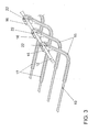
- Figs. 1-3 show suspension pads or portions thereof in different process stages of a method according to an embodiment, wherein Fig. 3 is an enlarged view of Fig. 2 , and Fig. 4 shows an embodiment of an apparatus for performing the method.
- a suspension pad portion In Fig. 1 , an example for a suspension pad portion is shown.
- the suspension pad portion of Fig. 1 comprises the complete wire part of a suspension pad and in particular comprises two lateral side wires 12, 13 and a plurality of transverse wires 10 running between the lateral side wires 12 and 13.
- lateral side wires 12 and 13 are plastified wires, wherein transverse wires 10 are metal wires.
- transverse wires 10 are metal wires.
- other materials may be used as well, for example lateral side wires 12 and 13 may be metal wires as well.
- the transverse wires 10 each have a convolution 14 in a middle portion thereof which gives a predetermined resiliency to the respective transverse wires. Furthermore, at a bent portion 11, the transverse wires 10 are bent. Such bending may be provided to accommodate a suspension pad to the seat where it is to be installed.
- the suspension pad to be fabricated from the suspension pad portion of Fig. 1 may be designed for installing at a right front seat of an automobile, and a symmetrical suspension pad where the bent portion is at the other lateral side may be provided for installation in a left front seat.
- no bending or bending on both sides of the suspension pad may be provided depending on a seating device where the suspension pad is to be installed.
- the transverse wires 10 are coupled to the lateral side wires 12, 13 by winding the transverse wires 10 around the lateral side wires 12, 13.
- the transverse wires 10 end at the lateral side wires 12, 13.
- the transverse wires after being wound around the lateral side wires may extend beyond the lateral side wires in order to provide anchor points to attach the suspension pad to a seat frame.
- a suspension pad portion like the one shown in Fig. 1 is formed in a pad forming station 26.
- wire is supplied to the pad forming station as raw material, and transverse wires are wound around lateral side wires and provided with convolutions and bent portions like explained with reference to Fig. 1 .
- the suspension pad portion after the suspension pad portion has been formed, it is transferred to a molding station 27 where, in the currently discussed embodiment, it is completely placed in a molding form 29 and subjected to an injection molding process, i.e. overmolded with a plastic material like polypropylene.
- the transfer of the suspension pad portion from the pad forming station to the molding station may be done automatically, for example using a conveyor belt, or it may be done manually.
- the pad forming station 26 may also be spatially separate from the molding station 27, for example in a different building or in different plant of a manufacturer.
- FIG. 2 An embodiment of a suspension pad according to the present invention which results from such an injection molding process applied to the suspension pad portion of Fig. 1 is shown in Figs. 2 and 3 , wherein Fig. 3 shows a partial enlarged view of Fig. 2 .
- the four wires in the middle of the suspension pad have a comparatively long plastic portion 17, whereas the plastic portions 15 of the transverse wires at the border of the suspension pad are comparatively shorter.
- Such different lengths of overmolding may be provided depending on the structure of a seat frame or seat where the suspension pad is to be mounted to prevent contact between the metallic transverse wires with metal parts of the seat frame or the seat. Therefore, the length distribution of the plastic portions 15, 17 and also 20 is not limited to the one shown in the embodiment, but may be adapted freely depending on the application of the suspension pad.
- thickened plastic portions 16 are provided at the side of the bent portion 11. As already mentioned thickened plastic portions 16 are provided. As best seen in Fig. 3 , these thickened portions 16 cover the portions where the transverse wires 10 are wound around the lateral side wire 12 as indicated by reference numeral 22. Therefore, the transverse wires 10 are securely fixed to the lateral side wires 12, and furthermore a scraping of the portions 22 of the transverse wires 10 on the lateral side wire 12 is prevented, which in turn prevents the generation of unwanted mechanical noise.
- a band-like portion 19 spanning all transverse wires 10 and terminating at an anchoring portion 18 on the convolution 14 of the topmost transverse wire 10 in Fig. 2 is provided by the molding process.
- Band-like portion 19 together with anchoring portion 18 provides additional stability to the suspension pad and maintains a predetermined distance between transverse wires 10.
- an embodiment of a suspension pad according to the present invention is finished and ready for integration into a seat.
- additional elements may be provided to the suspension pad during the overmolding process.
- an coupling element 23 is molded onto the lateral side wire 13 for coupling the lateral side wire 13 to a Bowden cable of an adjustment mechanism, said Bowden cable comprising a sleeve 24 and a wire 25 running within said sleeve.
- the basic structure of coupling element 23 may be the same as the structure of coupling element described in the above reference, but is not provided as a separate clip, but directly molded onto lateral side wire 13 during the injection molding performed in the molding station 27 of the embodiment of Fig. 4 .
- coupling elements for fixing additional adjusting elements to the pad and also coupling elements for coupling the suspension pad to a seat frame may also be provided in the injection molding process.
- the attachment of adjustment means like the above-mentioned Bowden cables may, in the embodiment of Fig. 4 , be performed in an optional finalizing station 28.
- the transverse wires 10 could be provided with the lateral side wire 12 attached thereto and placed together in a molding form to provide band-like portion 19, anchoring portion 18 as well as plastic portions 15, 16 and 17, and then the lateral side wire 13 would be attached to the transverse wires and the plastic portions 20, 21 would be provided by a further molding step.
- Such an embodiment may in particular be used when different plastic materials are used for overmolding.
- different plastic materials may also be used in a single overmolding step by providing a plurality of injection ports for the different plastic materials in the molding form.
Landscapes
- Engineering & Computer Science (AREA)
- Mechanical Engineering (AREA)
- Manufacturing & Machinery (AREA)
- Aviation & Aerospace Engineering (AREA)
- Transportation (AREA)
- Injection Moulding Of Plastics Or The Like (AREA)
- Casting Or Compression Moulding Of Plastics Or The Like (AREA)
Priority Applications (3)
| Application Number | Priority Date | Filing Date | Title |
|---|---|---|---|
| EP07002815A EP1955836A1 (fr) | 2007-02-09 | 2007-02-09 | Procédé et appareil pour la fabrication d'un tampon de suspension et tampon de suspension correspondant |
| CN200880004449A CN101622116A (zh) | 2007-02-09 | 2008-02-08 | 用于制造悬置垫的方法和设备以及对应的悬置垫 |
| PCT/EP2008/000990 WO2008095732A1 (fr) | 2007-02-09 | 2008-02-08 | Procédé et appareil pour fabriquer un support de suspension et support de suspension correspondant |
Applications Claiming Priority (1)
| Application Number | Priority Date | Filing Date | Title |
|---|---|---|---|
| EP07002815A EP1955836A1 (fr) | 2007-02-09 | 2007-02-09 | Procédé et appareil pour la fabrication d'un tampon de suspension et tampon de suspension correspondant |
Publications (1)
| Publication Number | Publication Date |
|---|---|
| EP1955836A1 true EP1955836A1 (fr) | 2008-08-13 |
Family
ID=38137554
Family Applications (1)
| Application Number | Title | Priority Date | Filing Date |
|---|---|---|---|
| EP07002815A Withdrawn EP1955836A1 (fr) | 2007-02-09 | 2007-02-09 | Procédé et appareil pour la fabrication d'un tampon de suspension et tampon de suspension correspondant |
Country Status (3)
| Country | Link |
|---|---|
| EP (1) | EP1955836A1 (fr) |
| CN (1) | CN101622116A (fr) |
| WO (1) | WO2008095732A1 (fr) |
Cited By (1)
| Publication number | Priority date | Publication date | Assignee | Title |
|---|---|---|---|---|
| KR20160019670A (ko) * | 2014-08-12 | 2016-02-22 | 현대자동차주식회사 | 차량용 시트백 서스펜션 어셈블리 및 이의 제조방법 |
Families Citing this family (1)
| Publication number | Priority date | Publication date | Assignee | Title |
|---|---|---|---|---|
| CN102079259A (zh) * | 2011-01-21 | 2011-06-01 | 金文哲 | 车辆座椅用钢丝悬挂装置及其制造方法 |
Citations (5)
| Publication number | Priority date | Publication date | Assignee | Title |
|---|---|---|---|---|
| EP1236610A2 (fr) * | 2001-03-02 | 2002-09-04 | Schwarzbich, Jörg | Procédé de fabrication d'un appui lombaire |
| DE10129721A1 (de) * | 2001-06-20 | 2003-01-09 | Federnwerke Marienberg Gmbh | Rückenlehne eines Sitzes, insbesondere Fahrzeugsitz |
| EP1593547A1 (fr) * | 2004-05-06 | 2005-11-09 | Fico Cables, Lda | Toile de suspension avec liaisons de plastic |
| DE102004021936A1 (de) * | 2004-05-04 | 2005-12-01 | Federnwerke Marienberg Gmbh | Rückenlehne für einen Fahrzeugsitz |
| EP1733650A1 (fr) * | 2005-06-15 | 2006-12-20 | L&P Swiss Holding Company | Dispositif de câble de traction et ensemble support réglable utilisant ce dispositif de câble de traction |
-
2007
- 2007-02-09 EP EP07002815A patent/EP1955836A1/fr not_active Withdrawn
-
2008
- 2008-02-08 CN CN200880004449A patent/CN101622116A/zh active Pending
- 2008-02-08 WO PCT/EP2008/000990 patent/WO2008095732A1/fr not_active Ceased
Patent Citations (5)
| Publication number | Priority date | Publication date | Assignee | Title |
|---|---|---|---|---|
| EP1236610A2 (fr) * | 2001-03-02 | 2002-09-04 | Schwarzbich, Jörg | Procédé de fabrication d'un appui lombaire |
| DE10129721A1 (de) * | 2001-06-20 | 2003-01-09 | Federnwerke Marienberg Gmbh | Rückenlehne eines Sitzes, insbesondere Fahrzeugsitz |
| DE102004021936A1 (de) * | 2004-05-04 | 2005-12-01 | Federnwerke Marienberg Gmbh | Rückenlehne für einen Fahrzeugsitz |
| EP1593547A1 (fr) * | 2004-05-06 | 2005-11-09 | Fico Cables, Lda | Toile de suspension avec liaisons de plastic |
| EP1733650A1 (fr) * | 2005-06-15 | 2006-12-20 | L&P Swiss Holding Company | Dispositif de câble de traction et ensemble support réglable utilisant ce dispositif de câble de traction |
Cited By (3)
| Publication number | Priority date | Publication date | Assignee | Title |
|---|---|---|---|---|
| KR20160019670A (ko) * | 2014-08-12 | 2016-02-22 | 현대자동차주식회사 | 차량용 시트백 서스펜션 어셈블리 및 이의 제조방법 |
| KR101683976B1 (ko) | 2014-08-12 | 2016-12-07 | 현대자동차주식회사 | 차량용 시트백 서스펜션 어셈블리 및 이의 제조방법 |
| US9914249B2 (en) | 2014-08-12 | 2018-03-13 | Hyundai Motor Company | Seat back suspension assembly for vehicle and method of manufacturing the same |
Also Published As
| Publication number | Publication date |
|---|---|
| CN101622116A (zh) | 2010-01-06 |
| WO2008095732A1 (fr) | 2008-08-14 |
Similar Documents
| Publication | Publication Date | Title |
|---|---|---|
| CN100471723C (zh) | 具有塑料链节的悬挂座垫 | |
| CA1296435C (fr) | Dispositif de fixation de garniture, plus particulierement de garniture de sieges d'automobile | |
| CN101287396B (zh) | 牵引线设置和使用所述牵引线设置的可调式支撑组合件 | |
| US20070110914A1 (en) | Wire harness arranging-purpose wire holding member and wire harness arranging-method | |
| EP1955836A1 (fr) | Procédé et appareil pour la fabrication d'un tampon de suspension et tampon de suspension correspondant | |
| JP2010538594A (ja) | 導線、ホース等を案内する装置 | |
| JP5578019B2 (ja) | 車両用シートのパッドおよびその製造方法 | |
| CN100372709C (zh) | 带有消能线缆的座椅安全带预拉紧器 | |
| CN111845499A (zh) | 具有包覆模制的风扇格栅的座椅悬架 | |
| KR101683976B1 (ko) | 차량용 시트백 서스펜션 어셈블리 및 이의 제조방법 | |
| US6890464B2 (en) | Method of manufacturing waterproof wire harness | |
| US9452700B2 (en) | Method for manufacturing a suspension mat | |
| CN101111174B (zh) | 一种将支撑结构可调节的安装在座椅中的座椅结构 | |
| KR101782323B1 (ko) | 차량 안전벨트용 와이어로프 조립체의 제조공정 | |
| US6624361B2 (en) | Method of waterproofing wire harness | |
| WO2010048515A1 (fr) | Élément de retenue d’habillage esthétique et procédé pour son utilisation | |
| CN115625845B (zh) | 线束包胶方法、心轴、线束包胶模具及线束 | |
| GB2328708A (en) | Attaching material to a seat | |
| KR102088884B1 (ko) | 스트레이트유닛 및 그것을 이용한 와이어하네스 설치방법 | |
| EP2014196A1 (fr) | Ensemble de couplage d'une structure de support de siège sur un support d'assise, structure de siège et procédé de fabrication correspondants | |
| EP1780076B1 (fr) | Dispositif de fixation et procédé et dispositif de fabrication associé | |
| EP4023491A1 (fr) | Structure de fixation pour mousse d'assise | |
| KR102134830B1 (ko) | 스트레이트유닛 및 그것을 이용한 와이어하네스 설치방법 | |
| KR102134831B1 (ko) | 스트레이트유닛 및 그것을 이용한 와이어하네스 설치방법 | |
| JPH11117456A (ja) | Pc鋼より線の定着部構造 |
Legal Events
| Date | Code | Title | Description |
|---|---|---|---|
| PUAI | Public reference made under article 153(3) epc to a published international application that has entered the european phase |
Free format text: ORIGINAL CODE: 0009012 |
|
| AK | Designated contracting states |
Kind code of ref document: A1 Designated state(s): AT BE BG CH CY CZ DE DK EE ES FI FR GB GR HU IE IS IT LI LT LU LV MC NL PL PT RO SE SI SK TR |
|
| AX | Request for extension of the european patent |
Extension state: AL BA HR MK RS |
|
| 17P | Request for examination filed |
Effective date: 20090203 |
|
| AKX | Designation fees paid |
Designated state(s): DE FR GB |
|
| 17Q | First examination report despatched |
Effective date: 20090610 |
|
| STAA | Information on the status of an ep patent application or granted ep patent |
Free format text: STATUS: THE APPLICATION IS DEEMED TO BE WITHDRAWN |
|
| 18D | Application deemed to be withdrawn |
Effective date: 20091021 |